Page 1178 of 5135
I30111
I30156
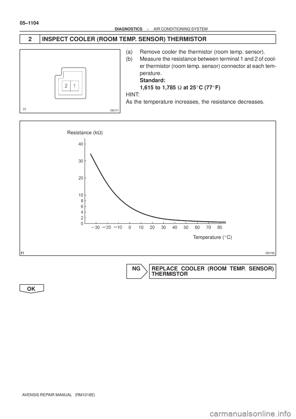
Resistance (k�)
Temperature (�C)
05±1104
± DIAGNOSTICSAIR CONDITIONING SYSTEM
AVENSIS REPAIR MANUAL (RM1018E)
2 INSPECT COOLER (ROOM TEMP. SENSOR) THERMISTOR
(a) Remove cooler the thermistor (room temp. sensor).
(b) Measure the resistance between terminal 1 and 2 of cool-
er thermistor (room temp. sensor) connector at each tem-
perature.
Standard:
1,615 to 1,785 � at 25�C (77�F)
HINT:
As the temperature increases, the resistance decreases.
NG REPLACE COOLER (ROOM TEMP. SENSOR)
THERMISTOR
OK
Page 1179 of 5135
±
DIAGNOSTICS AIR CONDITIONING SYSTEM
05±1105
AVENSIS REPAIR MANUAL (RM1018E)
3CHECK HARNESS AND CONNECTOR(COOLER (ROOM TEMP. SENSOR)
THERMISTOR ± A/C AMPLIFIER)
(a)Check for an open or short circuit in harness and connector between terminal TR an\
d SG±5 of A/C
amplifier (See page 01±32).
NG REPAIR OR REPLACE HARNESS ORCONNECTOR
OK
4 READ OUTPUT DTC
(a) Clear the DTCs.
(b) Read the DTC at least 8.5 minutes after turning the ignition switch ON. Standard: Normal codes are output.
MG REPLACE AIR CONDITIONING AMPLIFIER
OK
SYSTEM OK
Page 1180 of 5135

PROBLEM SYMPTOMS TABLE
If the normal code is displayed during DTC check although the problem still occurs, c")
050TM±13
05±1100
±
DIAGNOSTICS AIR CONDITIONING SYSTEM
AVENSIS REPAIR MANUAL (RM1018E)
PROBLEM SYMPTOMS TABLE
If the normal code is displayed during DTC check although the problem still occurs, check the circuits for
each problem symptom in the order given in the table below, and proceed to the relevant troubleshooting.
SymptomSuspect AreaSee page
Whole functions of the A/C system does not operate.
1. IG power source circuit
2. A/C amplifier assy
3. Engine ECU 1AZ±FSE: 1AZ±FE:
1ZZ±FE/3ZZ±FE:
1CD±FTV:05±1144
05±1098 05±294
05±149 05±5
05±528
Air Flow Control : No blower operation
1. Blower motor circuit
2. Heater relay circuit
3. Blower w/fan motor sub±assy
4. A/C amplifier assy05±1148
05±1146
05±1148
05±1098
Air Flow Control : No blower control1. Blower motor circuit05±1148
Air Flow Control : Insufficient air out
1. Blower w/fan motor sub±assy
2. Blower motor circuit
3. A/C amplifier assy05±1148
05±1148
05±1098
Temperature Control : Cool air does not come out
1. Volume of refrigerant
2. Drive belt tension
3. Refrigerant pressure
4. Air conditioner magnetic valve circut
5. Pressure sensor circuit
6. Air mix control servomotor circuit
7. Air mix damper position sensor circuit
8. Room temp. sensor circuit
9. Ambient temp. sensor circuit
10.A/C amplifier assy55±24
55±46
55±24
05±1151 05±1116
05±1133
05±1122
05±1102
05±1106
05±1098
Temperature Control : Warm air does not come out
1. Air mix control servomotor circuit
2. Air mix damper position sensor circuit
3. Ambient temp. sensor circuit
4. Room temp. sensor circuit
5. A/C amplifier assy
6. Heater radiator05±1133
05±1122
05±1106
05±1102
05±1098
±
Temperature Control : Output air is warmer or cooler than the set
temperature or response is slow.
1. Room temp. sensor circuit
2. Ambient temp. sensor circuit
3. Solar sensor circuit
4. Air mix damper position sensor circuit
5. Air mix control servomotor circuit
6. Evaporator temp. sensor circuit
7. A/C amplifier assy05±1102
05±110605±1113
05±1122
05±1133
05±1109
05±1098
Temperature Control : No temperature control (only Max. cool or Max. warm)
1. Room temp. sensor circuit
2. Ambient temp. sensor circuit
3. Solar sensor circuit
4. Air mix damper position sensor circuit
5. Air mix control servomotor circuit
6. Evaporator temp. sensor circuit
7. A/C amplifier assy05±1102
05±1106
05±1113
05±1122
05±1133
05±1109
05±1098
No air inlet control1. Recirculation damper servomotor circuit
2. A/C amplifier assy05±1153
05±1098
No air outlet control
1. Air outlet damper position sensor circuit
2. Air outlet control servomotor circuit
3. A/C amplifier assy05±1126
05±1136
05±1098
Page 1182 of 5135

05C7K±01
I36145
A15A16
1211
2423 19 1615
20191817161514131211 8 7 6 5 4 3 2 1
10 9 8 7 6 5 4 3 2 1 10 9
2221 1817 141320 05±1098
± DIAGNOSTICSAIR CONDITIONING SYSTEM
AVENSIS REPAIR MANUAL (RM1018E)
TERMINALS OF ECU
1. AIR CONDITIONER AMPLIFIER ASSY
Terminal No. (Symbols)Wiring ColorConditionSpecification
A16±5 (BLW) ±
A16±13 (GND)R ± W±BIG SW: ON
Front blower: OperatePulse generation
A16±7 (PRE) ±
A16±18 (SG)L±W ± G±W
Start engine
Refrigerant pressure: 0 kPa (0 kgf/cm2, 0 psi) � 3,138 MPa
(32.0 kgf/cm2, 455 psi)
0.5 � 4.8 V
A15±20 (MPX±) ±
A16±13 (GND)P ± W±BMultiplex communication circuit±
A15±10 (MPX+) ±
A16±13 (GND)P±B ± W±BMultiplex communication circuit±
A15±6 (FRS) ±
A16±13 (GND)P±B ± W±BIG SW: ON
R/F SW: RECIRCULATION � FRESH10 to 14 � Below 1.0 V
A15±5 (REC) ±
A16±13 (GND)R±Y ± W±BIG SW: ON
R/F SW: FRESH � RECIRCULATION10 to 14 � Below 1.0 V
A16±17 (HR) ±
A16±13 (GND)GR±R ± W±BIG SW: ON
Front blower: OFF � Operate10 to 14 � Below 1.0 V
A15±4 (AOF) ±
A16±13(GND)L±B ± W±BIG SW: ON
Mode switch: DEF. � FACEBelow 1.0 � 10 to 14 V
A15±3 (AOD) ±
A16±13 (GND)LG±B ± W±BIG SW: ON
Mode switch: FACE � DEF.Below 1.0 � 10 to 14 V
A16±12 (IG) ±
A16±13 (GND)R±W ± W±BIG SW: LOCK � ONBelow 10 to 14 V
A15±2 (AMPH) ±
A16±13 (GND)W ± W±BIG SW: ON
Set passenger side temp.: MAX. COOL � MAX. HOTBelow 1.0 � 10 to 14 V
A15±1 (AMPC) ±
A16±13 (GND)Y ± W±BIG SW:
Set passenger side temp.: MAX HOT � MAX. COOLBelow 1.0 � 10 to 14 V
A15±12 (AMDH) ±
A16±13 (GND)P±L ± W±BIG SW:
Set driver side temp.: MAX. COOL � MAX. HOTBelow 1.0 � 10 to 14 V
A15±11 (AMDC) ±
A16±13 (GND)B ± W±BIG SW:
Set driver side temp.: MAX HOT � MAX. COOLBelow 1.0 � 10 to 14 V
A16±13 (GND) ±
Body groundW±B ± Body groundAlwaysContinuity
A16±24 (+B) ±
A16±13 (GND)W±R ± W±BAlways10 to 14 V
A16±8 (TPD) ±
A15±14 (SG±2)GR ± Y±RIG SW: ON
Set driver side temp.: MAX HOT � MAX. COOL1.0 � 4.0 V
A16±20 TPP ±
A15±13 (SG±1)V ± PIG SW: ON
Set passenger side temp.: MAX HOT � MAX. COOL1.0 � 4.0 V
A16±9 (TSD) ±
A16±13 (GND)LG ± W±BIG SW: ON
Solar sensor subject to electric light0.8 to 3.3 V
A16±21 (TSP) ±
A16±13 (GND)L ± W±BIG SW: ON
Solar sensor subject to electric light0.8 to 3.3 V
Page 1184 of 5135
05C7J±01
I35352
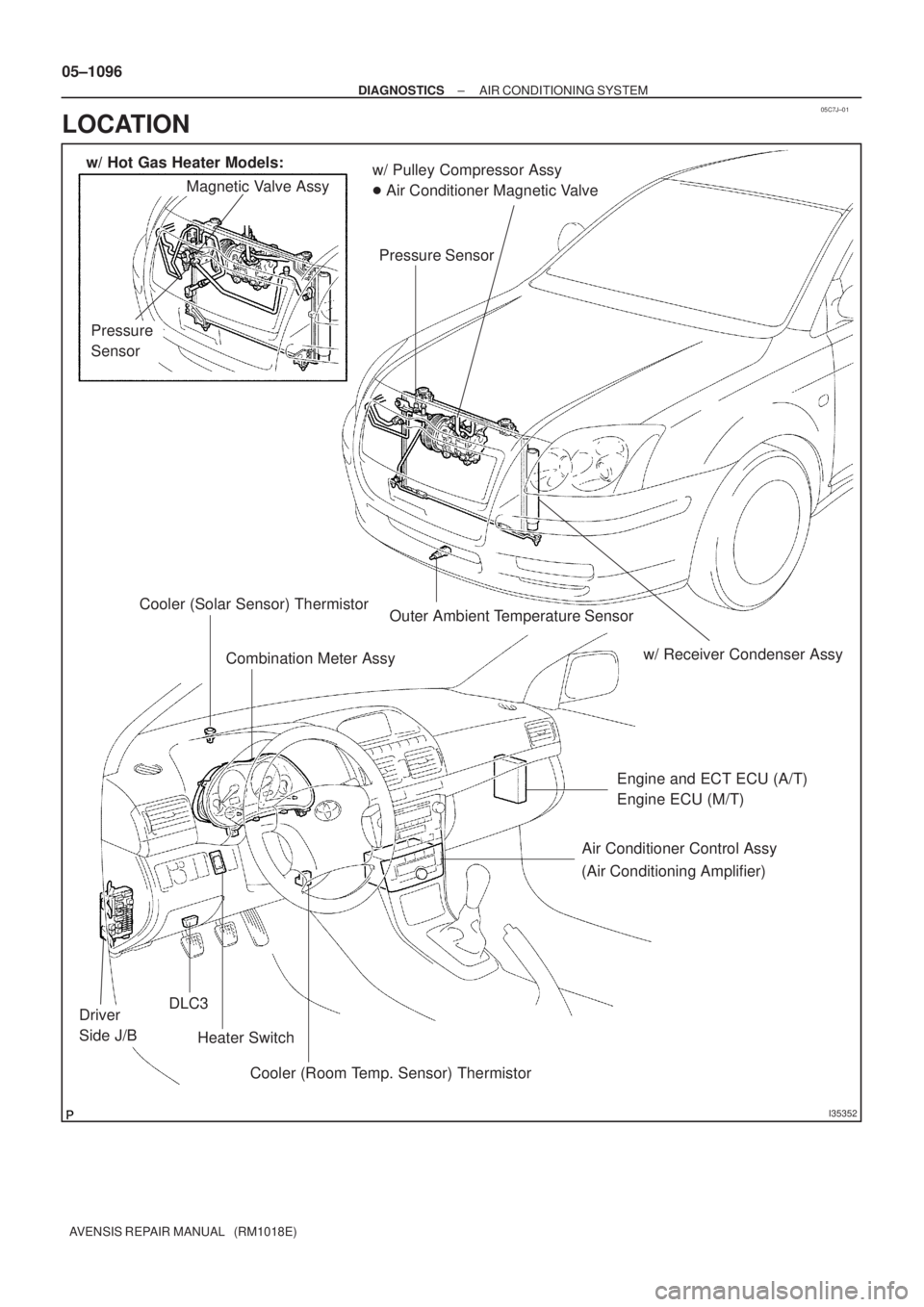
w/ Pulley Compressor Assy
� Air Conditioner Magnetic Valve
Pressure Sensor Magnetic Valve Assy
Heater Switch Cooler (Solar Sensor) Thermistor
Combination Meter Assy
Engine and ECT ECU (A/T)
Engine ECU (M/T)
Air Conditioner Control Assy
Cooler (Room Temp. Sensor) Thermistor
DLC3Driver
Side J/B
w/ Hot Gas Heater Models:
(Air Conditioning Amplifier)
Pressure
Sensor
Outer Ambient Temperature Sensor
w/ Receiver Condenser Assy
05±1096
± DIAGNOSTICSAIR CONDITIONING SYSTEM
AVENSIS REPAIR MANUAL (RM1018E)
LOCATION
Page 1185 of 5135
I35353
Recirculation Damper Servo Sub±assy
Mode Damper Servo Sub±assy
Evaporator Temp. Sensor
Evaporator
Airmix Damper Servo Sub±assy
Airmix No.2 Damper
Servo Sub±assy
Blower Motor ControlBlower w/ Fan Motor
Sub±assy
± DIAGNOSTICSAIR CONDITIONING SYSTEM
05±1097
AVENSIS REPAIR MANUAL (RM1018E)
Page 1191 of 5135

DIAGNOSTIC TROUBLE CODE CHART
If a malfunction code is displayed during the DTC check, check the")
05C7W±01
05±1166
± DIAGNOSTICSCOMBUSTION TYPE POWER HEATER SYSTEM
AVENSIS REPAIR MANUAL (RM1018E)
DIAGNOSTIC TROUBLE CODE CHART
If a malfunction code is displayed during the DTC check, check the circuit listed for that code in the table
below and proceed to the appropriate page.
DTC No.Description of faultComment / Remedy
000No malfunction±
010
011Overvoltage shutoff
Undervoltage shutoffVoltage between 1 and 5 at connector A > 16 V
Voltage between 1 and 5 at connector A < 10.2 V
(Voltage values must be present > 20 seconds)
Check battery, regulator and electrical leads.
012Overheating
Check temperature at temperature or overheating sensor >
125 �C
Check water circuit.
014Possible overheating detected
(Hardware threshold value)
Difference of measured values at temperature sensor > 15 �C
(min. 70 �C water temperature and metering pump in opera-
tion);
Check temperature sensor and overheating sensor, replace if
necessary.
017Overheating detected
(Hardware threshold value)
Temperature at temperature or overheating sensor > 130 �C,
emergency OFF if DTC No. 012 or 014 not is applicable;
Check water circuit, temperature sensor and overheating sen-
sor, replace if necessary.
020Glow plug breakCheck glow plug, replace if necessary.
021Glow plug output overloadCheck glow plug, replace if necessary.
030Combustion air blower motor
EMF outside perm. range.Blower impeller or burner motor fammed (frozen solid, dirty,
etc.)
Remedy jam, replace burner motor if necessary.
031Combustion air blower motor breakCheck the lead to combustion air motor (burner motor) for
continuity, replace if necessary.
032Combustion air blower motor short±circuit
Check combustion air blower motor (burner motor), replace if
necessary.
Check supply lead (chafed, etc.).
047Metering pump short±circuitCheck the supply lead to metering pump for short±circuit,
check metering pump, replace if necessary.
048Metering pump breakCheck the supply lead to metering pump for continuity, remedy
break, replace metering pump if necessary.
051Cold blow time exceeded
At start, if flame sensor above 70 �C, > 240 sec.;
Check exhaust gas combustion air supply, check flame sen-
sor, replace if necessary.
052Safety time exceeded
When all perm. start attempts used up;
Check the fuel delivery and fuel supply.
Check exhaust gas and combustion air ducts.
054Flame cutout, High settingCheck the fuel delivery and fuel supply.
Check exhaust gas combustion air ducts.
056Flame cutout, LOW setting
Check exhaust gas combustion air ducts.
If combustion OK � Check the flame sensor, replace if neces-
sary.
060Temperature conrol sensor break
Check connecting leads.
Resistance value between 2 and 10 connector B > 2 M� (if
break)
061Temperature control sensor short±circuit
Check connecting leads.
Resistance value between 2 and 10 at connector B < 2 M� (If
short± circuit)
064Flame sensor break
Check connecting leads.
Resistance value between 7 and 14 at connector B > 3,040 �
(If break)
065Flame sensor short±circuit
Check connecting leads.
Resistance value between 7 and 14 at connector B > 780 � (If
short±circuit)
Page 1192 of 5135
± DIAGNOSTICSCOMBUSTION TYPE POWER HEATER SYSTEM
05±1167
AVENSIS REPAIR MANUAL (RM1018E)DTC No.Comment / Remedy Description of fault
071Surface sensor break
Check connecting leads.
Resistance value between 4 and 11 at connector B > 2 �� (If
break)
072Surface sensor short±circuit
Check connecting leads.
Resistance value between 4 and 11 at connector B > 50 � (If
short±circuit)
090
092
093Control unit detective (Internal fault / Reset)
Control unit detective (ROM error)
Control unit detective (RAM error)
Control unit malfunction due to interference voltage from ve-
hicle electrical system;
possible causes low batteries, chargers, other sources of
interference; eliminate interference voltages.
Internal faults detected in microprocessor / memory detected.
Replace control unit.
097Internal control unit faultsOther faults which cannot lead to DTC No. 90, 92 and 93,
replace control unit.

3CHECK HARNESS AND CONNECTOR(COOLER (ROOM TEMP. SENSOR)
THERMISTOR ± A/C AMPLIFIER)
(a)Check for an open or short cir")

DTC No.Comment / Remedy Description of fault
071Surface sensor break
Check connecting leads.
Resistance valu")