Page 1166 of 5135
Resistance of photodiode
Strength of solar radiationWeak Strong
High
Low
I35375
TSP A16 L21 A18
A/C Solar Sensor
2IF11A/C Control Assembly
L
TSD A16 LG9
3IF12
LG
S5±4 A16 O15
1IF13
O
± DIAGNOSTICSAIR CONDITIONING SYSTEM
05±1113
AVENSIS REPAIR MANUAL (RM1018E)
DTC 21 SOLAR SENSOR CIRCUIT(PASSENGER
SIDE)
CIRCUIT DESCRIPTION
A photo diode in the solar sensor detects solar radiation and
sends signals to the A/C amplifier.
DTC No.Detection ItemTrouble Area
Open or short in solar sensor circuit�Automatic light control sensor (solar sensor)
21
Open or short in solar sensor circuit.
(If the checking is being performed in a dark place, DTC 21g()
�Harness or connector between automatic light control sensor
(solar sensor) and A/C amplifier assy(gg ,
could be displayed.)(solar sensor) and A/C amplifier assy
�A/C amplifier assy
WIRING DIAGRAM
05C7M±01
Page 1167 of 5135

INSPECTION PROCEDURE
1INSPECT CO")
I33908
1
2
I37731
A16
TSD
TSP S5±4
1 23 45 67 89101112
13141516171819202123 2224
05±1114
±
DIAGNOSTICS AIR CONDITIONING SYSTEM
AVENSIS REPAIR MANUAL (RM1018E)
INSPECTION PROCEDURE
1INSPECT COOLER (SOLAR SENSOR) THERMISTOR
(a)Remove cooler (solar sensor) thermistor.
(b)Cover the sensor with a cloth, and check the cooler (solar sensor) thermistor resistance.
(1)Measure resistance between terminals 1 and 2 of
the cooler (solar sensor) thermistor.
Resistance: � � (No continuity)
HINT:
Connect the ohmmter positive (+) lead to terminal 2 and the
ohmmeter negative (±) lead to terminal 1 of the cooler (solar
sensor) thermistor.
(c)Remove the cloth from the cooler (solar sensor) thermis- tor, and subject the sensor to the electric light and check
the cooler (solar sensor) thermistor resistance.
(1)Measure resistance between terminal 1 and 2 of the
cooler (solar sensor) thermistor.
Resistance: Approx. 10 k � (Continuity)
HINT:
Connect the positive (+) lead to ohmmeter to terminal 2 and
negative (±) lead to terminal 1 of the cooler (solar sensor)
thermistor.
NGREPLACE COOLER (SOLAR SENSOR) THERMISTOR
OK
2CHECK HARNESS AND CONNECTOR(COOLER (SOLAR SENSOR) THERMISTOR ± A/C AMPLIFIER)
(a)Check for an open or short circuit in harness and connec-
tor between solar sensor and A/C amplifier
(See page 01±32).
NG REPAIR OR REPLACE HARNESS OR CONNECTOR
OK
Page 1169 of 5135
I35373
A/C Control Assembly
16
A15 SG±4 W±G
1 A19
A/C Thermistor
2B10
A16 TE
± DIAGNOSTICSAIR CONDITIONING SYSTEM
05±1109
AVENSIS REPAIR MANUAL (RM1018E)
DTC 13 EVAPORATOR TEMPERATURE SENSOR
CIRCUIT
CIRCUIT DESCRIPTION
This sensor detects the temperature inside the cooling unit and sends the appropriate signals to the A/C
amplifier.
DTC No.Detection ItemTrouble Area
�Cooler thermistor No.1 (evaporator temp. sensor)
13Open or short in evaporator temperature sensor circuit.
()
�Harness or connector between cooler thermistor No.1 (evap-
orator tempsensor) and A/C amplifier assyorator temp. sensor) and A/C amplifier assy
�A/C amplifier assy
WIRING DIAGRAM
050TN±10
Page 1171 of 5135
��
E50650
I30156
Resistance (k �)
Temperature (�C)
±
DIAGNOSTICS AIR CONDITIONING SYSTEM
05±1111
AVENSIS REPAIR MANUAL (RM1018E)
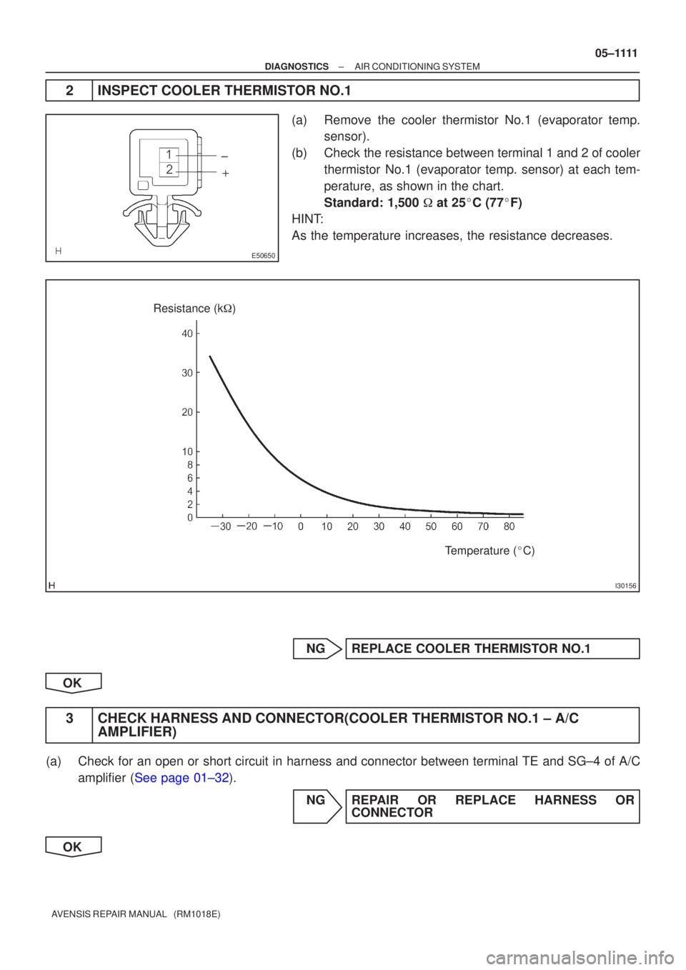
2INSPECT COOLER THERMISTOR NO.1
(a)Remove the cooler thermistor No.1 (evaporator temp.
sensor).
(b)Check the resistance between terminal 1 and 2 of cooler thermistor No.1 (evaporator temp. sensor) at each tem-
perature, as shown in the chart.
Standard: 1,500 � at 25 �C (77 �F)
HINT:
As the temperature increases, the resistance decreases.
NGREPLACE COOLER THERMISTOR NO.1
OK
3CHECK HARNESS AND CONNECTOR(COOLER THERMISTOR NO.1 ± A/C AMPLIFIER)
(a)Check for an open or short circuit in harness and connector between term\
inal TE and SG±4 of A/C
amplifier (See page 01±32).
NG REPAIR OR REPLACE HARNESS ORCONNECTOR
OK
Page 1173 of 5135
I35374
C10P±B
22 1
IC1
A1 A/C Ambient Temp. SensorA15 MPX±A/C Control Assembly Combination Meter
*1: 1CD±FTV
*2: 1AZ±FSE
*3: 1AZ±FE, 1ZZ±FE, 3ZZ±FEIC1 P±B P P10 20
11 I14
Integration Relay
C10P
E9A15 MPX+ 20
E1018 Engine and ECT ECU (A/T)Engine ECU (M/T)
(*2) (*1)E921
E1029
(*2) (*1) 14
10 13
P±B
C10W
IE14 12
W
21
C10W±R
IE115 11
W±R MPX2 MPX1
MPX2 MPX1 23
E9
(*3)29
E9
(*3) 05±1106
± DIAGNOSTICSAIR CONDITIONING SYSTEM
AVENSIS REPAIR MANUAL (RM1018E)
DTC 12 AMBIENT TEMPERATURE SENSOR CIRCUIT
CIRCUIT DESCRIPTION
This sensor detects the temperature outside the cabin and sends the appropriate signals to the A/C amplifier.
DTC No.Detection itemTrouble Area
12Open or short in ambient temperature sensor circuit
�Thermistor assy (ambient temp. sensor)
�Harness or connector between thermistor assy (ambient
temp. sensor) and combination meter
�Combination meter
�Harness or connector between combination meter and A/C
amplifier assy
�A/C amplifier assy
WIRING DIAGRAM
05C7L±01
Page 1174 of 5135
I37583
C10±12C10±11
I30156
Resistance (k�)
Temperature (�C)
± DIAGNOSTICSAIR CONDITIONING SYSTEM
05±1107
AVENSIS REPAIR MANUAL (RM1018E)
INSPECTION PROCEDURE
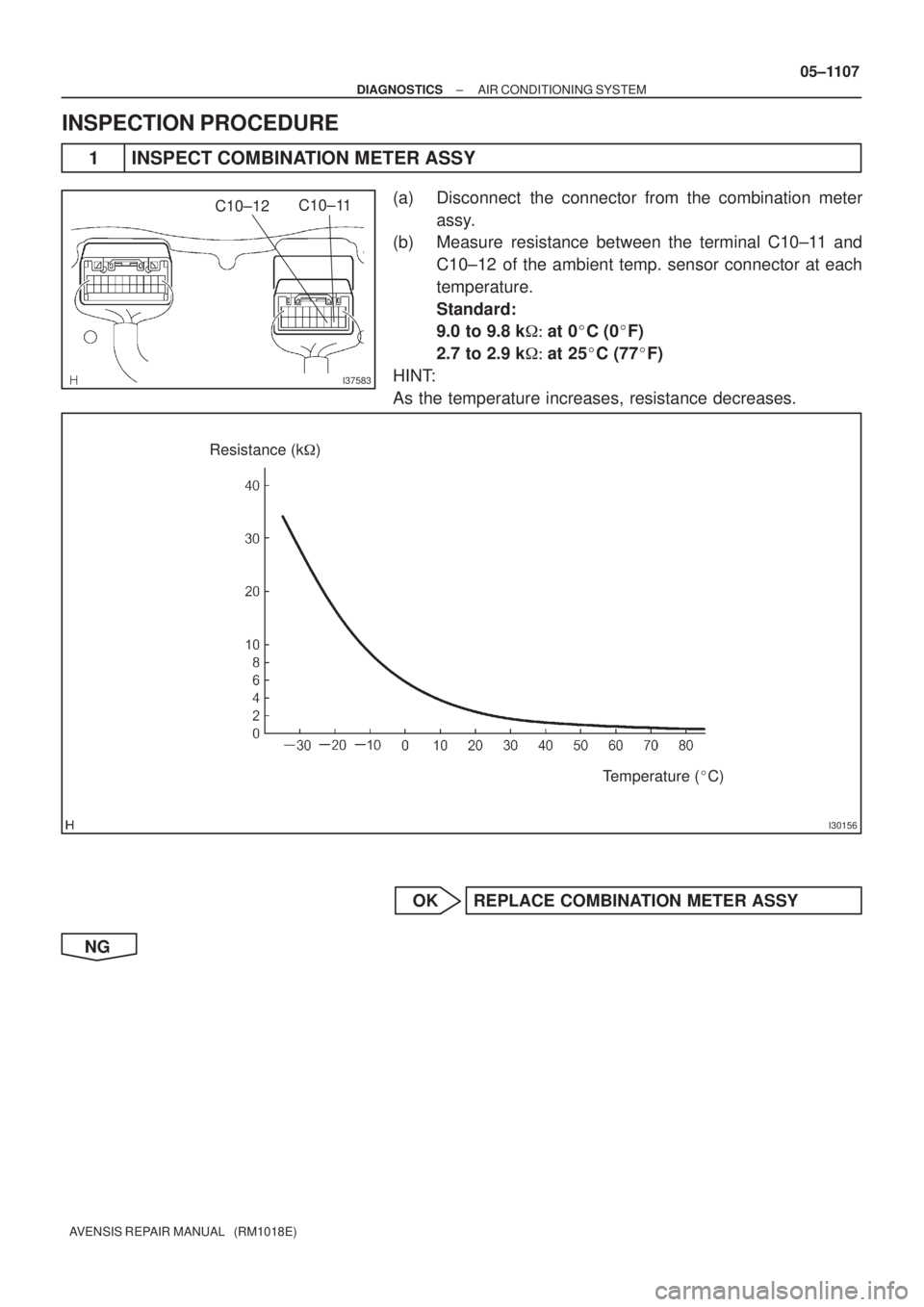
1 INSPECT COMBINATION METER ASSY
(a) Disconnect the connector from the combination meter
assy.
(b) Measure resistance between the terminal C10±11 and
C10±12 of the ambient temp. sensor connector at each
temperature.
Standard:
9.0 to 9.8 k��at 0�C (0�F)
2.7 to 2.9 k��at 25�C (77�F)
HINT:
As the temperature increases, resistance decreases.
OK REPLACE COMBINATION METER ASSY
NG
Page 1175 of 5135
05±1108
± DIAGNOSTICSAIR CONDITIONING SYSTEM
AVENSIS REPAIR MANUAL (RM1018E)
2 CHECK HARNESS AND CONNECTOR(COMBINATION METER ± OUTER AMBIENT
TEMPERATURE SENSOR)
(a) Disconnect the connector from ambient temp. sensor.
(b) Check continuity between the terminal C10±11 (12) of combination meter assy and the terminal A1±1
(2) of ambient temp. sensor connector.
Standard: Continuity
NG REPAIR OR REPLACE HARNESS AND
CONNECTOR
OK
3 READ OUTPUT DTC
(a) Clear the DTCs.
(b) Read the DTC at least 8.5 minutes after turning the ignition switch ON.
Standard: Normal codes are output.
NG REPLACE OUTER AMBIENT TEMPERATURE
SENSOR
OK
PROCEED TO NEXT CIRCUIT INSPECTION SHOWN ON PROBLEM SYMPTOMS TABLE
Page 1176 of 5135
I35373
A/C Control Assembly
22
6 A16 TR
SG±5 GR
G
12 A17
A/C Room Temp. Sensor
A16 05±1102
± DIAGNOSTICSAIR CONDITIONING SYSTEM
AVENSIS REPAIR MANUAL (RM1018E)
DTC 11 ROOM TEMPERATURE SENSOR CIRCUIT
CIRCUIT DESCRIPTION
This sensor detects the temperature inside the cabin and sends the appreciate signals to the A/C amplifier.
DTC No.Detection itemTrouble Area
11Open or short in room temperature sensor circuit
�Cooler thermistor (room temp. sensor)
�Harness or connector between cooler thermistor (room temp.
sensor) and A/C amplifier assy
�A/C amplifier assy
WIRING DIAGRAM
05A7M±02


DTC 13 EVAPORATOR TEMPERATURE SENSOR
CI")


2 CHECK HARNESS AND CONNECTOR(COMBINATION METER ± OUTER AMBIENT
TEMPERATURE SENSOR)
(a) Disconnect the connector from")

DTC 11 ROOM TEMPERATURE SENSOR CIRC")