Page 1114 of 5135

I36146
Display code R/FDEFLHD:
I36147
Display code RHD:R/FDEF
Blower level Step No.Display
codeConditions
Air flow bent Air inlet damper Compressor
ºCOOLº side (Full closed)Air mix damper
OFF FRESH
FACE 0
1
2
3
6
7
8
9
104
51
16
16
16
16
16
16
16
31 0
1
2
3
6
7
8 4
5
9FACE
FACE
FACE
B/L
FOOT1
FOOT/ DEF.
DEF.FRESH
ON
ON
ON
ON
ON
ON
ONºCOOLº side (Full closed)
ºCOOLº side (Full closed)
ºCOOLº side (Full closed)
ºCOOLº/ ºHOT º (50 % open)
ºHOTº side (Full opened)
FOOT FACE1FRESH
FRESH
RECIRCULATION
RECIRCULATION
RECIRCULATION
RECIRCULATION
RECIRCULATION
RECIRCULATIONHot gas magnetic valve
ºCOOLº/ ºHOT º (50 % open)
ºHOTº side (Full opened)
ºHOTº side (Full opened)ON
ON
OFF
OFF
OFF
OFF
OFF
OFF
OFF
OFF OFF
ºHOTº side (Full opened) OFF
± DIAGNOSTICSAIR CONDITIONING SYSTEM
05±1093
AVENSIS REPAIR MANUAL (RM1018E)
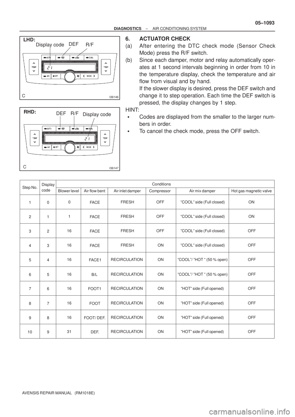
6. ACTUATOR CHECK
(a) After entering the DTC check mode (Sensor Check
Mode) press the R/F switch.
(b) Since each damper, motor and relay automatically oper-
ates at 1 second intervals beginning in order from 10 in
the temperature display, check the temperature and air
flow from visual and by hand.
If the slower display is desired, press the DEF switch and
change it to step operation. Each time the DEF switch is
pressed, the display changes by 1 step.
HINT:
�Codes are displayed from the smaller to the larger num-
bers in order.
�To cancel the check mode, press the OFF switch.
Page 1136 of 5135
F44865
Combination Meter Power Steering ECU
C11V±W 18
SPD J10H
J10H
J20H
J20H
E155
V±W
(*1) (*2) (*1) (*2)
*1: LHD
*2: RHDJ/C
± DIAGNOSTICSELECTRONIC MOTOR POWER STEERING SYSTEM
05±1067
AVENSIS REPAIR MANUAL (RM1018E)
DTC C1541/41 Speed Sensor Malfunction
DTC C1542/42 Speed Sensor Malfunction
DTC C1571/71 Speed Sensor Malfunction (Test mode)
CIRCUIT DESCRIPTION
DTC No.DTC Detecting ConditionTrouble Area
C1541/41
Speed sensor malfunction
�Speed sensor
�Speed sensor circuit
C1542/42
Speed sensor malfunction�Speed sensor circuit
�Skid control ECU assy
Cbiti tC1571/71Speed sensor malfunction (Test mode)�Combination meter assy
�Power steering ECU assy
WIRING DIAGRAM
0579L±02
Page 1140 of 5135
I35378
A23
Air Mix Control Servo Motor (Driver Side) A/C Control Assembly
M
MAX
HOT4P±L
A15 AMDH12
MAX
COOL5B
A15 AMDC11
PT 3GR
A16 TPD8
VZ 2Y±B
A16 S5±22
GND 1Y±R
A15 SG±214
± DIAGNOSTICSAIR CONDITIONING SYSTEM
05±1139
AVENSIS REPAIR MANUAL (RM1018E)
DTC 46 AIR MIX DAMPER CONTROL SERVOMOTOR
CIRCUIT (DRIVER SIDE)
CIRCUIT DESCRIPTION
The air mix damper servo sub±assy is controlled by the A/C amplifier and moves the air mix damper to the
desired position.
DTC No.Detection ItemTrouble Area
46Air mix damper position sensor value does not change even if
A/C amplifier operated air mix damper control servomotor.
�Air mix damper servo sub±assy (air mix damper control )
�Harness or connector between air mix damper servo sub±
assy (air mix damper control servomotor) and A/C amplifier
�A/C amplifier assy
WIRING DIAGRAM
05A8A±02
Page 1143 of 5135
I35378
A25
Air Vent Mode Control Servo Motor A/C Control Assembly
M
FACE 5L±B
A15 AOF4
DEF 4LG±B
A15 AOD3
PT 3GR±R
A16 TPM19
VZ 2BR±W
A16 S5±314
GND 1G±W
A15 SG±315 05±1136
± DIAGNOSTICSAIR CONDITIONING SYSTEM
AVENSIS REPAIR MANUAL (RM1018E)
DTC 43 AIR OUTLET DAMPER CONTROL
SERVOMOTOR CIRCUIT
CIRCUIT DESCRIPTION
This circuit turns the servomotor and changes each mode damper position by the signals from the A/C ampli-
fier assy. When the AUTO switch is on, the A/C amplifier changes the mode automatically between ºFACEº,
ºBI±LEVELº, ºFOOTº and ºFOOT/DEFº according to the temperature setting.
DTC No.Detection ItemTrouble Area
43Air mode damper position sensor value does not change even
if A/C amplifier operated mode damper control servomotor.
�Mode damper servo sub±assy (mode damper control)
�Harness or connector between mode damper servo sub±
assy (mode damper control) and A/C amplifier assy
�A/C amplifier assy
WIRING DIAGRAM
05A87±02
Page 1146 of 5135

I35377
A24
Air Mix Control Servo Motor (Front Passenger Side) A/C Control Assembly
MA15 AMPH W
(*1)
W
(*2) W
(*2)5
IQ1 MAX 4 (*1)
HOT 5 (*2)
A15 AMPC Y
(*1)
Y
(*2) Y
(*2)4
IQ1 MAX 5 (*1)
COOL 4 (*2)2
1
A16 TPP V
(*1)
V
(*2) V
(*2)3
IQ1 PT20
3
A16 S5±1 R
(*1)
R
(*2) R
(*2)1
IQ1 VZ 2 (*1)
1 (*2)1
A15 SG±1 P
(*1)
P
(*2) P
(*2)2
IQ1 GND
1 (*1)
2 (*2)13
*1: LHD
*2: RHD
± DIAGNOSTICSAIR CONDITIONING SYSTEM
05±1133
AVENSIS REPAIR MANUAL (RM1018E)
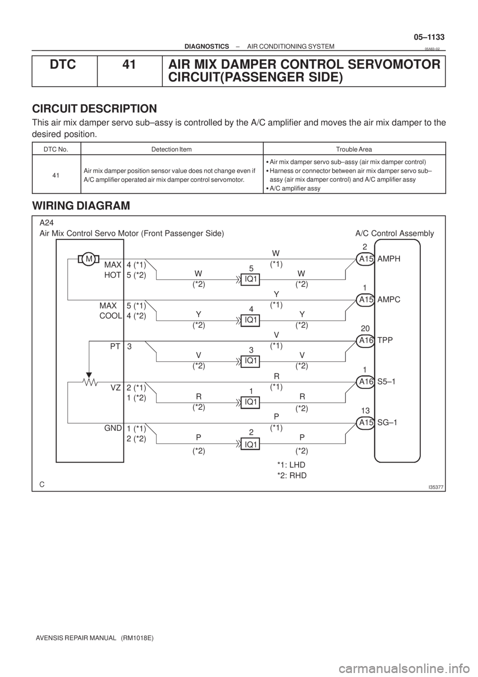
DTC 41 AIR MIX DAMPER CONTROL SERVOMOTOR
CIRCUIT(PASSENGER SIDE)
CIRCUIT DESCRIPTION
This air mix damper servo sub±assy is controlled by the A/C amplifier and moves the air mix damper to the
desired position.
DTC No.Detection ItemTrouble Area
41Air mix damper position sensor value does not change even if
A/C amplifier operated air mix damper control servomotor.
�Air mix damper servo sub±assy (air mix damper control)
�Harness or connector between air mix damper servo sub±
assy (air mix damper control) and A/C amplifier assy
�A/C amplifier assy
WIRING DIAGRAM
05A83±02
Page 1149 of 5135
4(V)
1
0
100%
TPI terminal voltage
Damper opening angle
I35378
A23
Air Mix Control Servo Motor (Driver Side) A/C Control Assembly
M
MAX
HOT4P±L
A15 AMDH12
MAX
COOL5B
A15 AMDC11
PT 3GR
A16 TPD8
VZ 2Y±B
A16 S5±22
GND 1Y±R
A15 SG±214
± DIAGNOSTICSAIR CONDITIONING SYSTEM
05±1129
AVENSIS REPAIR MANUAL (RM1018E)
DTC 36 AIR MIX DAMPER POSITION SENSOR
CIRCUIT (DRIVER SIDE)
CIRCUIT DESCRIPTION
This sensor detects the position of the air mix damper and
sends the appropriate signals to the A/C amplifier. The position
sensor is built in the air mix damper servo sub±assy.
DTC No.Detection ItemTrouble Area
36Short to ground or power source circuit in air mix damper posi-
tion sensor circuit.
�Air mix damper servo sub±assy (Air mix damper position
sensor)
�Harness or connector between air mix damper servo sub±
assy (air mix damper position sensor) and A/C amplifier assy
�A/C amplifier assy
WIRING DIAGRAM
05A80±02
Page 1151 of 5135

I35383
RHD Models:
MAX. COOL MAX. HOT
12345
P
T V
Z GND
I36141
LHD Models:
MAX. COOL MAX. HOT
P T VZGND
±
DIAGNOSTIC SAIR CONDITIONING SYSTEM
05± 1131
A VENSIS RE PAIR MANUAL (RM1018E)
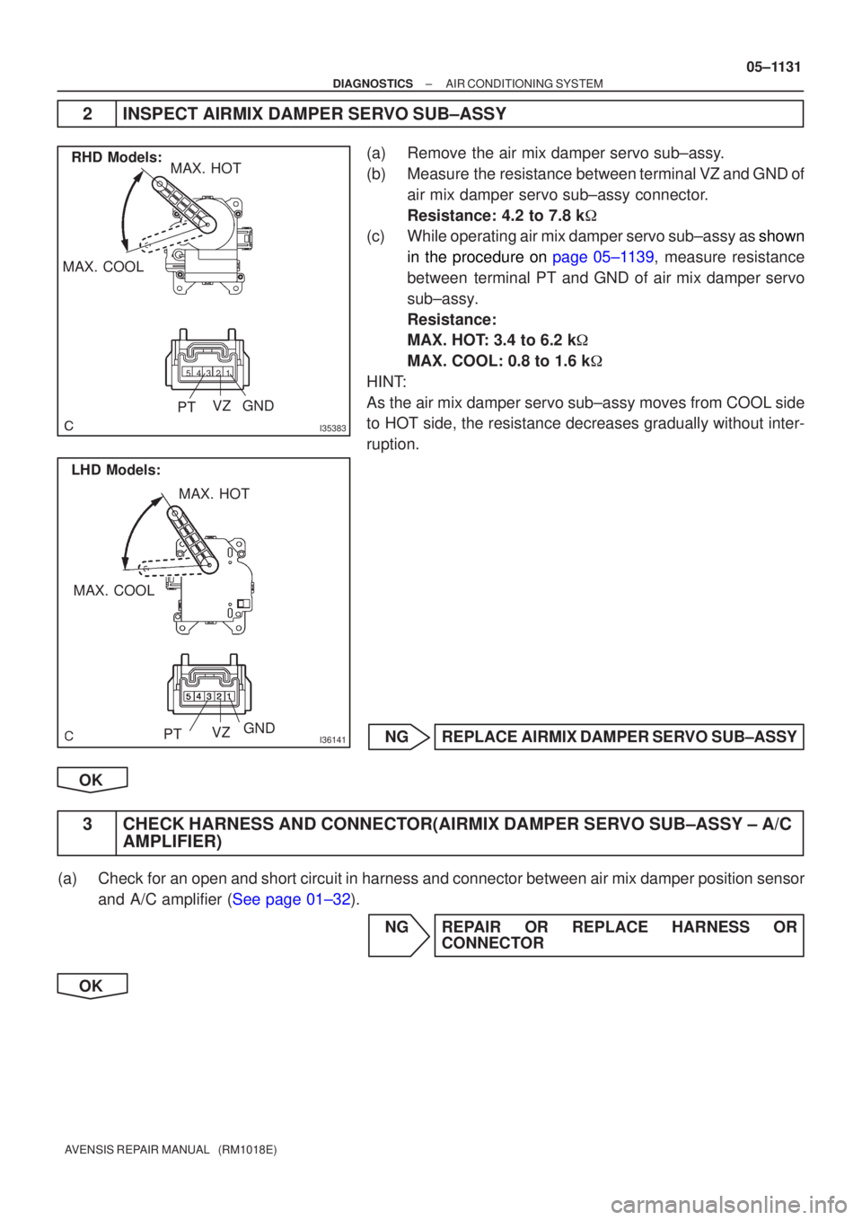
2 INSPEC T AIRMIX DAMPER SE RVO SUB±ASSY
(a ) Remov e the air mix damper servo sub±ass y.
(b ) Measur e the resistance between terminal VZ and GND of
air mix damper servo sub±assy connecto r.
Resistance: 4.2 to 7.8 k �
(c ) Whil e operating air mix damper servo sub±assy as shown
i n the procedure on page 05±1139 , measure resistance
betwee n terminal PT and GND of air mix damper servo
sub±ass y.
Resistance :
MAX. HO T: 3.4 to 6.2 k�
MAX. COOL: 0.8 to 1.6 k�
HIN T:
A s the air mix damper servo sub±assy moves from COOL side
t o HOT side, the resistance decreases gradually without inter-
ruption.
NG REPLAC E AIRMIX DAMPER SE RVO SUB±ASSY
OK
3 CHEC K HARNESS AND CONNEC TOR(AIRMIX DAMPER SE RVO SUB±ASSY ± A/C
AMPLIFIER)
(a ) Chec k for an open and short circuit in harness and connector between air mix damper p\
osition sensor
an d A/C amplifier ( See page 01±32 ).
NG REPAIR OR REPLACE HARNESS OR CONNECTOR
OK
Page 1153 of 5135
TPM terminal voltage
(V)
4
1
0 100%
Damper opening angle
I35378
A25
Air Vent Mode Control Servo Motor A/C Control Assembly
M
FACE 5L±B
A15 AOF4
DEF 4LG±B
A15 AOD3
PT 3GR±R
A16 TPM19
VZ 2BR±W
A16 S5±314
GND 1G±W
A15 SG±315 05±1126
± DIAGNOSTICSAIR CONDITIONING SYSTEM
AVENSIS REPAIR MANUAL (RM1018E)
DTC 33 AIR OUTLET DAMPER POSITION SENSOR
CIRCUIT
CIRCUIT DESCRIPTION
This sensor detects the position of the mode damper and sends
the appropriate signals to the A/C amplifier. The position sensor
is built in the mode damper servo sub±assy.
DTC No.Detection ItemTrouble Area
33Short to ground or power source circuit in mode damper posi-
tion sensor circuit.
�Mode damper servo sub±assy (mode damper position sen-
sor)
�Harness or connector between mode damper servo sub±
assy (mode damper position sensor) and A/C amplifier assy
�A/C amplifier assy
WIRING DIAGRAM
05A7X±02