Page 1094 of 5135

(5) Disconnect and connect the terminal Tc of DLC3 20
times within 20 seconds.
(6) Che")
C52361
DLC3:
CGTs 05±1050
± DIAGNOSTICSELECTRONIC MOTOR POWER STEERING SYSTEM
AVENSIS REPAIR MANUAL (RM1018E)
(5) Disconnect and connect the terminal Tc of DLC3 20
times within 20 seconds.
(6) Check the DTC C1515/15 output.
(c) Perform the torque sensor zero point calibration.
HINT:
�Do not touch the steering wheel.
�Check that the DTC for except C1515/15 is not output.
(1) Stop the vehicle and turn the ignition switch to OFF.
(2) Using SST, connect terminals Ts and CG of DLC3
and turn the ignition switch to ON.
SST 09843±18040
(3) Disconnect the SST.
SST 09843±18040
(4) Check the DTC is not output.
8. CALIBRATION OF TORQUE SENSOR ZERO POINT
(USING HAND±HELD TESTER)
HINT:
Perform this operation in the following cases.
�When removing and installing ºsteering wheel assemblyº,
ºtilt steering column assemblyº and ºsteering gear assem-
blyº.
�When replacing power steering ECU assy.
(a) Place front wheels and steering wheel facing straight
ahead.
(b) Perform the torque sensor zero point initialization.
HINT:
If the power steering ECU assy is replaced, initialization is not
necessary.
(1) Stop the vehicle.
(2) Connect the hand±held tester to the DLC3.
(3) Select the ºTRQ SENS ADJUSTº mode on the
hand±held tester.
(4) Select the ºZERO POINT INITIALIZEº.
(5) Following the screen instructions, perform the
torque sensor zero point initialization.
(c) Perform the torque sensor zero point calibration.
HINT:
Do not touch the steering wheel.
(1) Connect the hand±held tester to the DLC3.
(2) Turn the ignition switch ON.
(3) Select the ºTRQ SENS ADJUSTº mode on the
hand±held tester.
(4) Select the ºZERO POINT ADJUSTº.
(5) Following the screen instructions, perform the
torque sensor zero point calibration.
Page 1095 of 5135
±
DIAGNOSTICS ELECTRONIC MOTOR POWER STEERING SYSTEM
05±1051
AVENSIS REPAIR MANUAL (RM1018E)
9.REPLACE POWER STEERING ECU ASSY
NOTICE:
Thoroughly check the procedures for removing and instal-
ling the power steering ECU assy when replacing it. Do the
same operation or procedure for the removing and instal-
ling the steering column assy.
(a)Remove the power steering ECU assy (See page
50±20).
(1) Mark the clamp position on the torque sensor wireharness in order to reinstall the wire harness as
shown in the illustration.
(2) Disconnect the torque sensor wire harness from the
clamp.
NOTICE:
In case the clamp will be reused, pay attention so as not to
damage it. (3) Disconnect the connectors.
(4) LHD:Remove the 2 bolts, screw and power steering ECU
assy.
(5) RHD: Remove the 2 bolts, 2 screws and power steering
ECU assy.
Page 1096 of 5135
F44857
LHD:RHD:
Torque Sensor Wire Harness Clamp
Marks
Power Steering ECU Assy
Front
Motor Wire Harness
Torque Sensor
Wire Harness
Front
Torque Sensor
Wire Harness
Motor Wire Harness
Power Steering ECU Assy
Torque Sensor Wire Harness Clamp
Marks
Screw
Bolt A
Bolt A
Bolt B
Bolt B
Screw
05±1052
±
DIAGNOSTICS ELECTRONIC MOTOR POWER STEERING SYSTEM
AVENSIS REPAIR MANUAL (RM1018E)
(b)Install the power steering ECU assy (See page 50±20).
(1) LHD:Install the power steering ECU assy with the 2 bolts
and screw.
Torque:
Bolt A: 8.0 N �m (82 kgf �cm, 71 in. �lbf)
Bolt B: 15.5 N �m (158 kgf �cm, 11 ft �lbf)
(2) RHD: Install the power steering ECU assy with the 2 bolts
and 2 screws.
Torque:
Bolt A: 8.0 N �m (82 kgf �cm, 71 in. �lbf)
Bolt B: 15.5 N �m (158 kgf �cm, 11 ft �lbf)
(3) Connect the connectors.
Page 1097 of 5135
± DIAGNOSTICSELECTRONIC MOTOR POWER STEERING SYSTEM
05±1053
AVENSIS REPAIR MANUAL (RM1018E)
(4) Align the marks on the torque sensor wire harness
with the clamp, as shown in the illustration.
NOTICE:
�When reusing the clamp, check that there is no dam-
age on it.
�When reinstalling the wire harness, make sure there
is no twist in the harness or with other wire harness.
10. FAIL SAFE FUNCTION
(a) If the power steering ECU assy detects a trouble, the ECU
assy halt, fix or lower the steering power assist in order to
protect the system.
HINT:
Repeating the steering operation when stopping or driving at
low speed, or leaving the steering wheel turn fully for long hours
will lower the amount of power assist in order to prevent power
steering ECU assy from heating up. In this case, not operating
the steering for about 10 minutes with engine idle will lead the
fail safe function to return the normal state.
Page 1110 of 5135

DIAGNOSTIC TROUBLE CODE CHART
If malfunction code is displayed during the DTC check (sensor check), ch\
eck")
050TJ±13
05±1094
±
DIAGNOSTICS AIR CONDITIONING SYSTEM
AVENSIS REPAIR MANUAL (RM1018E)
DIAGNOSTIC TROUBLE CODE CHART
If malfunction code is displayed during the DTC check (sensor check), ch\
eck the circuit listed for the code
in the table below (Proceed to the page given for that circuit).
DTC No.
(See Page)Detection ItemTrouble AreaMemory
00Normal±±
11 *1
(05±1102)
Room temperature sensor circuit
(open/short)� Cooler thermistor (room temp. sensor)
� Harness or connector between cooler thermistor (room
temp. sensor) and A/C amplifier assy
� A/C amplifier assy
�
(8.5 min. or more)
12 *2
Ambient temperature sensor circuit
(open/short)� Thermistor assy (ambient temp. sensor)
� Harness or connector between thermistor assy (ambient
temp. sensor) and combination meter
�Combination meter�12
(05±1106)� Combination meter
� Harness or connector between combination meter and A/C
amplifier assy
� A/C amplifier assy�
(8.5 min. or more)
13
(05±1109)
Evaporator temperature sensor circuit
(open/short)� Cooler thermistor No.1 (evaporator temp. sensor)
� Harness or connector between cooler thermistor No.1
(evaporator temp. sensor) and A/C amplifier assy
� A/C amplifier assy
�
(8.5 min. or more)
21 *3
Solar sensor circuit (open) (Passenger
side)� Automatic light control sensor (solar sensor)
� Harness or connector between automatic light control sen-
( l ) d A/C lifi
�
(8.5 min. or more)
21
(05±1113)
Solar sensor circuit (short) (Passenger
side)sor (solar sensor) and A/C amplifier assy
� A/C amplifier assy
±
23
(05±1116)
Pressure sensor circuit� A/C tube assy (pressure sensor)
� Harness or connector between A/C tube assy (pressure
sensor) and A/C amplifier assy
� A/C amplifier assy
±
24 *3
Solar sensor circuit (open)
(Driver side)�Automatic light control sensor (solar sensor)
� Harness or connector between automatic light control sen-
( l ) d A/C lifi
�
(8.5 min. or more)
24
(05±1119)
Solar sensor circuit (short)
(Driver side)sor (solar sensor) and A/C amplifier assy
� A/C amplifier assy
±
31
(05±1122)
Air mix damper position sensor circuit
(Passenger side)� Air mix damper servo sub±assy (air mix damper position
sensor)
� Harness or connector between air mix damper servo sub±
assy (air mix damper position sensor) and A/C amplifier
assy
� A/C amplifier assy
�
(1 min. or more)
33
(05±1126)
Air outlet damper position sensor circuit� Mode damper servo sub±assy (mode damper position sen-
sor)
� Harness or connector between mode damper servo sub±
assy (mode damper position sensor) and A/C amplifier assy
� A/C amplifier assy
�
(1 min. or more)
36
(05±1129)
Air mix damper position sensor circuit
(Driver side)� Air mix damper servo sub±assy (Air mix damper position
sensor)
� Harness or connector between air mix damper servo sub±
assy (air mix damper position sensor) and A/C amplifier
assy
� A/C amplifier assy
�
(1 min. or more)
41
(05±1133)
Air mix damper control servomotor
(Passenger side)� Air mix damper servo sub±assy (air mix damper control)
� Harness or connector between air mix damper servo sub±
assy (air mix damper control) and A/C amplifier assy
� A/C amplifier assy
�
(15 sec.)
Page 1111 of 5135
±
DIAGNOSTICS AIR CONDITIONING SYSTEM
05±1095
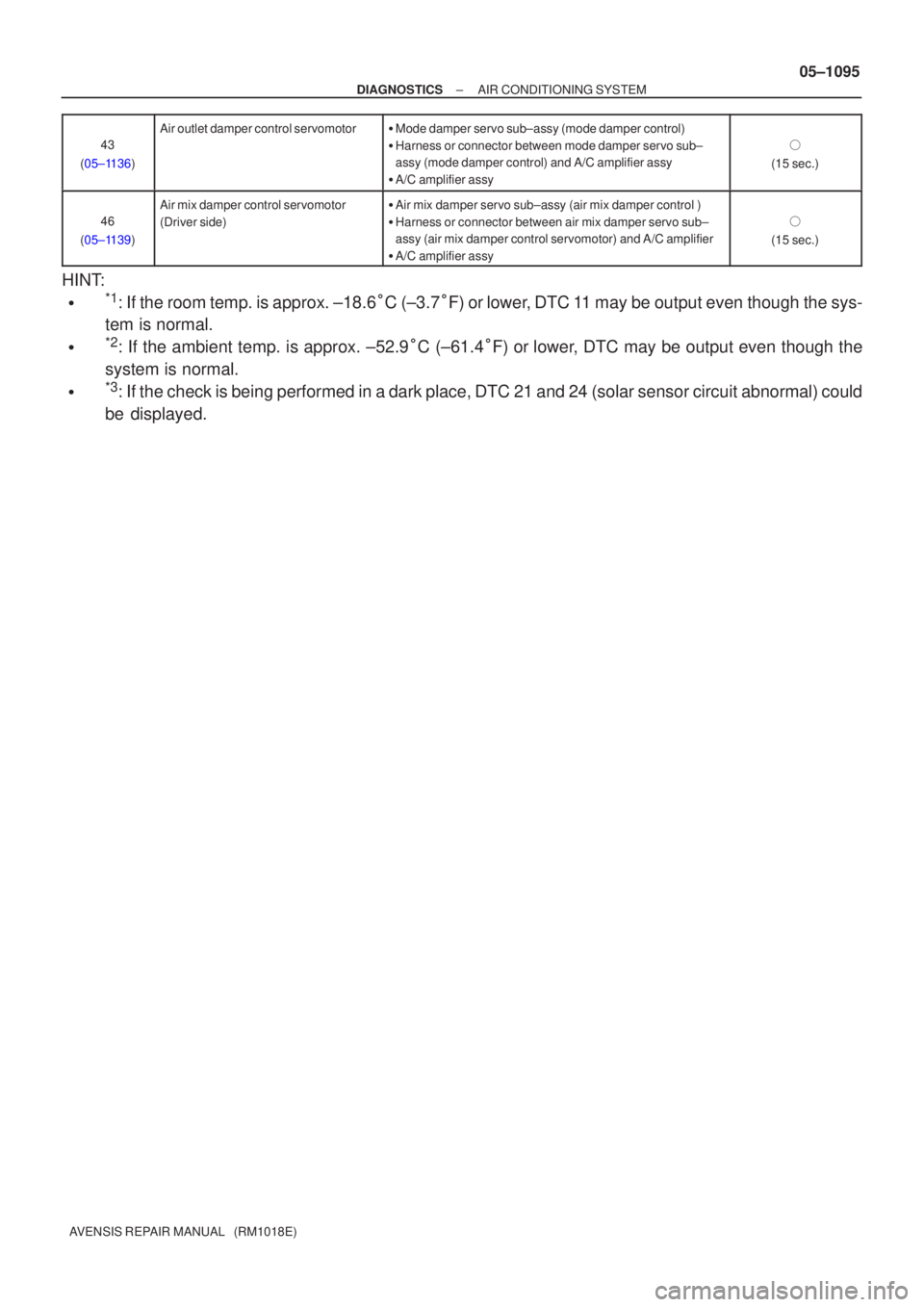
AVENSIS REPAIR MANUAL (RM1018E)43
(05±1136)
Air outlet damper control servomotor� Mode damper servo sub±assy (mode damper control)
� Harness or connector between mode damper servo sub±
assy (mode damper control) and A/C amplifier assy
� A/C amplifier assy
�
(15 sec.)
46
(05±1139)
Air mix damper control servomotor
(Driver side)� Air mix damper servo sub±assy (air mix damper control )
� Harness or connector between air mix damper servo sub±
assy (air mix damper control servomotor) and A/C amplifier
� A/C amplifier assy
�
(15 sec.)
HINT:
�*1: If the room temp. is approx. ±18.6 �C (±3.7 �F) or lower, DTC 11 may be output even though the sys-
tem is normal.
�*2: If the ambient temp. is approx. ±52.9 �C (±61.4 �F) or lower, DTC may be output even though the
system is normal.
�*3: If the check is being performed in a dark place, DTC 21 and 24 (solar \
sensor circuit abnormal) could
be displayed.
Page 1112 of 5135

(continuous operation)
DTC Check
(Sensor Check)
(stepped operation)
Canc")
05C7I±01
Turn the ignition switch ON with AUTO
and R/F switches remain being preseed.
Indicator Check
DTC Check
(Sensor Check)
(continuous operation)
DTC Check
(Sensor Check)
(stepped operation)
Cancel check mode and start A/C control.
OFF
OFF
DEF
Actuator Check
(continuous operaiton)OFF
Actuator Check
(stepped operation)OFF
If both AUTO switch and R/F switch are
not pressed at the same time.
R/F
R/FR/F
AUTO
: Indicates a switch operation
AUTOAUTO
DEF
DEF
DEF
I35392
AUTO R/F
AC2163
Blinking pattern
ON
OFF1 sec.4times
1 sec.
± DIAGNOSTICSAIR CONDITIONING SYSTEM
05±1091
AVENSIS REPAIR MANUAL (RM1018E)
PRE±CHECK
1. LIST OF OPERATION METHODS
By operating each of the A/C control switches as shown in the below diagram, it is possible to enter the diag-
nosis check mode.
2. INDICATOR CHECK
(a) Turn the ignition switch ON while pressing the A/C control
AUTO switch and R/F switch simultaneously.
(b) Check that the indicators come on and go off 4 times in
succession at a interval of a second.
HINT:
�After the indicator check is completed, the system enters
the DTC mode begins automatically.
�Press the OFF switch to cancel the check mode.
Page 1113 of 5135

3.DTC CHECK (SENSOR CHECK)
(a)After the")
I35392
DTCDEF
I35417ECU±B2
Fuse block:
3
2
145678
910111213141516
DLC3
A04550
05±1092
±
DIAGNOSTICS AIR CONDITIONING SYSTEM
AVENSIS REPAIR MANUAL (RM1018E)
3.DTC CHECK (SENSOR CHECK)
(a)After the indicator check is completed, the system enters the DTC check mode automatically.
(b)Read the codes displayed on the panel. Refer to the list of codes on page 05±1094 when reading the codes.
(Trouble codes are outputed at the temperature display.)
(c) If the slower display is desired, press the DEF switch and
change it to the stop operation. Each time the DEF switch
is pressed, the display changes by 1 step.
4. CLEARING DTC
(a) To clear diagnostic trouble code, there are 2 ways. (1) During sensor check, press the ºDEFº switch andºDUALº switch at the same time.
(2) Pull the ECU±B2 fuse in fuse block for 20 seconds or longer to clear the DTC memory.
5. CHECK DLC3
(a) The vehicle engine and ECT ECU uses the ISO 9141±2 (Euro±OBD)/ISO 14230 (M±OBD) communication proto-
col. The terminal arrangement of the DLC3 complies with
ISO 15031±3 and matches the ISO 9141±2/ISO 14230
format.
Terminal No.Connection/Voltage or ResistanceCondition
7Bus + Line/Pulse generationDuring transmission
4Chassis Ground � Body Ground/1 � or lessAlways
5Signal Ground � Body Ground/1 � or lessAlways
16Battery Positive � Body Ground/9 ± 14 VAlways

9.REPLACE POWER STEERING ECU ASSY
NOTICE:
Thoroughly check the procedures for removing and instal-
ling")


(4) Align the marks on the torque sensor wire harness
with the clamp, as shown in the illustration.
NOTI")