Page 1018 of 5135
0567R±10
D30681
Combination Meter
(MIL)
Kick±down Switch Stop Lamp
Switch Assy
Shift Lock Control Unit
(Transmission Control Switch)ECM
DLC3
Shift Solenoid Valve SL
Shift Solenoid Valve SLT
Shift Solenoid Valve ST Shift Solenoid Valve S1 Shift Solenoid Valve SB Shift Solenoid Valve S2Park/neutral Position
Switch AssyTransmission Wire
(ATF Temperature Sensor)
Speed Sensor (NT) LHD:
05±998± DIAGNOSTICSELECTRONIC CONTROLLED AUTOMATIC
TRANSAXLE [ECT] (U341E)
AVENSIS REPAIR MANUAL (RM1018E)
LOCATION
Page 1019 of 5135

AVENSIS REPAIR MANUAL (RM1018E)
DIAGNOSTIC TROUBLE CODE CHART
If a DTC is displayed during the DTC check, check](/manual-img/14/57441/w960_57441-1018.png "TOYOTA AVENSIS 2005 Service Repair Manual 0567Q±07
05±996±
DIAGNOSTICS ELECTRONIC CONTROLLED AUTOMATIC
TRANSAXLE [ECT](U341E)
AVENSIS REPAIR MANUAL (RM1018E)
DIAGNOSTIC TROUBLE CODE CHART
If a DTC is displayed during the DTC check, check")
0567Q±07
05±996±
DIAGNOSTICS ELECTRONIC CONTROLLED AUTOMATIC
TRANSAXLE [ECT](U341E)
AVENSIS REPAIR MANUAL (RM1018E)
DIAGNOSTIC TROUBLE CODE CHART
If a DTC is displayed during the DTC check, check the circuit listed in th\
e table below and proceed to the
page given.
*
1 : � ... MIL light up
DTC No.
(See Page)Detection ItemTrouble AreaMIL *1Memory
P0500
(05±98)Vehicle Speed Sensor Malfunc-
tion
� Combination meter
� Open or short in speed sensor circuit
� Speed sensor
� ECM
��
P0710
(05±1003)Transmission Fluid Temperature
Sensor Circuit Malfunction
(ATF Temperature Sensor)
� Open or short in ATF temp. sensor circuit
��
P0711
(05±1005)
Transmission Fluid Temperature
Sensor Circuit Range/Perfor-
mance
(ATF Temperature Sensor)
Oen or short in AT F tem. sensor circuit
� Transmission wire (ATF temperature sensor)
� ECM
��
P0750
(05±1007)Shift Solenoid ºAº Malfunction
(Shift Solenoid Valve S1)� Shift solenoid valve S1 is stuck open or closed
� Valve body is blocked up or stuck
� Automatic transaxle (clutch, brake or gear etc.)
��
P0753
(05±1010)Shift Solenoid ºAº Electrical
(Shift Solenoid Valve S1)� Open or short in shift solenoid valve S1 circuit
� Shift solenoid valve S1
� ECM
��
P0755
(05±1007)Shift Solenoid ºBº Malfunction
(Shift Solenoid Valve S2)� Shift solenoid valve S2 is stuck open or closed
� Valve body is blocked up or stuck
� Automatic transaxle (clutch, brake or gear etc.)
��
P0758
(05±1010)Shift Solenoid ºBº Electrical
(Shift Solenoid Valve S2)� Open or short in shift solenoid valve S2 circuit
� Shift solenoid valve S2
� ECM
��
P0770
(05±1013)Shift Solenoid ºEº Malfunction
(Shift Solenoid Valve SL)
� Shift solenoid valve SL is stuck open or closed
� Valve body blocked or stuck
� Shift solenoid valve SL
� Torque converter clutch
� Automatic transaxle (clutch, brake or gear etc.)
��
P0773
(05±1015)Shift Solenoid ºEº Electrical
(Shift Solenoid Valve SL)� Open or short in shift solenoid valve SL circuit
� Shift solenoid valve SL
� ECM
��
P1520
(05±1018)Stop Light Switch Circuit
� Open or short in stop light switch circuit
� Stop lamp switch assy
� ECM
��
P1725
(05±1019)NT Revolution Sensor Circuit
Malfunction
(Input Turbine Speed Sensor)� Open or short in speed sensor (NT) circuit
� Speed sensor (NT)
� ECM
��
P1760
(05±1021)Linear Solenoid for Line Pres-
sure Control Circuit Malfunction
(Shift Solenoid Valve SLT)� Open or short in shift solenoid valve SLT circuit
� Shift solenoid valve SLT
� ECM
��
P1780
(05±1024)Park/Neutral Position Switch
Malfunction� Short in park/neutral position switch circuit
� Park/Neutral position switch assy
� ECM
��
P1790
(05±1027)ST Solenoid Circuit Malfunction
(Shift Solenoid Valve ST)� Open or short in shift solenoid valve ST circuit
� Shift solenoid valve ST
� ECM
��
P1798
(05±1030)SB Solenoid Circuit Malfunction
(Shift Solenoid Valve SB)� Open or short in shift solenoid valve SB circuit
� Shift solenoid valve SB
� ECM
��
Page 1039 of 5135
![TOYOTA AVENSIS 2005 Service Repair Manual D26541
C3
Counter Gear Speed
SensorECM
26
E12 NC+ LG
2
34
E12 NC± LG±B 1
± DIAGNOSTICSELECTRONIC CONTROLLED AUTOMATIC
TRANSAXLE [ECT] (U241E(1AZ±FSE))05±965
AVENSIS REPAIR MANUAL (RM1018E)
DTC](/manual-img/14/57441/w960_57441-1038.png "TOYOTA AVENSIS 2005 Service Repair Manual D26541
C3
Counter Gear Speed
SensorECM
26
E12 NC+ LG
2
34
E12 NC± LG±B 1
± DIAGNOSTICSELECTRONIC CONTROLLED AUTOMATIC
TRANSAXLE [ECT] (U241E(1AZ±FSE))05±965
AVENSIS REPAIR MANUAL (RM1018E)
DTC")
D26541
C3
Counter Gear Speed
SensorECM
26
E12 NC+ LG
2
34
E12 NC± LG±B 1
± DIAGNOSTICSELECTRONIC CONTROLLED AUTOMATIC
TRANSAXLE [ECT] (U241E(1AZ±FSE))05±965
AVENSIS REPAIR MANUAL (RM1018E)
DTC P0793 INTERMEDIATE SHAFT SPEED SENSOR
ºAº
CIRCUIT DESCRIPTION
This sensor detects the rotation speed of the counter gear. By comparing the counter gear speed signal (NC)
with the direct clutch speed sensor signal (NT), the ECM detects the shift timing of the gears and appropriate-
ly controls the engine torque and hydraulic pressure according to various conditions. Thus smooth gear shift-
ing is performed.
DTC No.DTC Detection ConditionTrouble Area
P0793
ECM detects conditions (a), (b), (c) and (d) continuity for 5 sec.
or more: (1 trip detection logic)
(a) Vehicle speed: 50 km/h (20 mph) or more
(b) 2nd, 3rd or O/D gear
(c) Solenoid valves and park/neutral position switch are normal
(d) NC < 300 rpm
�Open or short in speed sensor (NC) circuit
�Speed sensor (NC)
�ECM
WIRING DIAGRAM
05C9H±01
Page 1040 of 5135
C58536
������C91565
NC+
NC±
05±966± DIAGNOSTICSELECTRONIC CONTROLLED AUTOMATIC
TRANSAXLE [ECT] (U241E(1AZ±FSE))
AVENSIS REPAIR MANUAL (RM1018E)
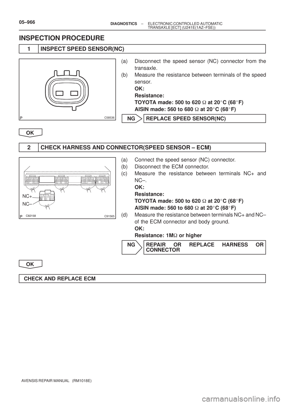
INSPECTION PROCEDURE
1 INSPECT SPEED SENSOR(NC)
(a) Disconnect the speed sensor (NC) connector from the
transaxle.
(b) Measure the resistance between terminals of the speed
sensor.
OK:
Resistance:
TOYOTA made: 500 to 620 � at 20�C (68�F)
AISIN made: 560 to 680 � at 20�C (68�F)
NG REPLACE SPEED SENSOR(NC)
OK
2 CHECK HARNESS AND CONNECTOR(SPEED SENSOR ± ECM)
(a) Connect the speed sensor (NC) connector.
(b) Disconnect the ECM connector.
(c) Measure the resistance between terminals NC+ and
NC±.
OK:
Resistance:
TOYOTA made: 500 to 620 � at 20�C (68�F)
AISIN made: 560 to 680 � at 20�C (68�F)
(d) Measure the resistance between terminals NC+ and NC±
of the ECM connector and body ground.
OK:
Resistance: 1M� or higher
NG REPAIR OR REPLACE HARNESS OR
CONNECTOR
OK
CHECK AND REPLACE ECM
Page 1041 of 5135
![TOYOTA AVENSIS 2005 Service Repair Manual D25466
12
12
(+)
(±)
± DIAGNOSTICSELECTRONIC CONTROLLED AUTOMATIC
TRANSAXLE [ECT] (U241E(1AZ±FSE))05±963
AVENSIS REPAIR MANUAL (RM1018E)
DTC P0776 PRESSURE CONTROL SOLENOID ºBº
PERFORMANCE (SH](/manual-img/14/57441/w960_57441-1040.png "TOYOTA AVENSIS 2005 Service Repair Manual D25466
12
12
(+)
(±)
± DIAGNOSTICSELECTRONIC CONTROLLED AUTOMATIC
TRANSAXLE [ECT] (U241E(1AZ±FSE))05±963
AVENSIS REPAIR MANUAL (RM1018E)
DTC P0776 PRESSURE CONTROL SOLENOID ºBº
PERFORMANCE (SH")
D25466
12
12
(+)
(±)
± DIAGNOSTICSELECTRONIC CONTROLLED AUTOMATIC
TRANSAXLE [ECT] (U241E(1AZ±FSE))05±963
AVENSIS REPAIR MANUAL (RM1018E)
DTC P0776 PRESSURE CONTROL SOLENOID ºBº
PERFORMANCE (SHIFT SOLENOID VALVE
SL2)
SYSTEM DESCRIPTION
The ECM uses signals from the vehicle speed sensor to detect the actual gear position (1st, 2nd, 3rd or O/D
gear).
Then the ECM compares the actual gear with the shift schedule in the ECM memory to detect mechanical
troubles of the shift solenoid valves and valve body.
DTC No.DTC Detecting ConditionTrouble Area
P0776The gear required by the ECM does not match the actual gear
when driving (2±trip detection logic)�Shift solenoid valve SL2 is stuck open or closed
�Valve body is blocked up or stuck
�Automatic transaxle (clutch, brake or gear etc.)
INSPECTION PROCEDURE
1 INSPECT SHIFT SOLENOID VALVE(SL2)
(a) Remove the shift solenoid valve SL2.
(b) Measure the resistance between terminals.
OK:
Resistance: 5.1 to 5.5 � at 20�C (68�F)
(c) Connect the positive (+) lead with a 21 W bulb to terminal
2 and the negative (±) lead to terminal 1 of the solenoid
valve connector, then check the movement of the sole-
noid valve.
OK:
The solenoid valve makes an operating noise.
NG REPLACE SHIFT SOLENOID VALVE(SL2)
OK
2 INSPECT TRANSMISSION VALVE BODY ASSY
NG REPAIR OR REPLACE TRANSMISSION VALVE
BODY ASSY
OK
05C9G±01
Page 1043 of 5135
![TOYOTA AVENSIS 2005 Service Repair Manual D25467
(+)(±)
05±962± DIAGNOSTICSELECTRONIC CONTROLLED AUTOMATIC
TRANSAXLE [ECT] (U241E(1AZ±FSE))
AVENSIS REPAIR MANUAL (RM1018E)
DTC P0766 SHIFT SOLENOID ºDº PERFORMANCE
(SHIFT SOLENOID VALVE](/manual-img/14/57441/w960_57441-1042.png "TOYOTA AVENSIS 2005 Service Repair Manual D25467
(+)(±)
05±962± DIAGNOSTICSELECTRONIC CONTROLLED AUTOMATIC
TRANSAXLE [ECT] (U241E(1AZ±FSE))
AVENSIS REPAIR MANUAL (RM1018E)
DTC P0766 SHIFT SOLENOID ºDº PERFORMANCE
(SHIFT SOLENOID VALVE")
D25467
(+)(±)
05±962± DIAGNOSTICSELECTRONIC CONTROLLED AUTOMATIC
TRANSAXLE [ECT] (U241E(1AZ±FSE))
AVENSIS REPAIR MANUAL (RM1018E)
DTC P0766 SHIFT SOLENOID ºDº PERFORMANCE
(SHIFT SOLENOID VALVE S4)
SYSTEM DESCRIPTION
The ECM uses signals from the vehicle speed sensor to detect the actual gear position (1st, 2nd, 3rd or O/D
gear).
Then the ECM compares the actual gear with the shift schedule in the ECM memory to detect mechanical
troubles of the shift solenoid valves and valve body.
DTC No.DTC Detecting ConditionTrouble Area
P0766The gear required by the ECM does not match the actual gear
when driving (2±trip detection logic)�Shift solenoid valve S4 is stuck open or closed
�Valve body is blocked up or stuck
�Automatic transaxle (clutch, brake or gear etc.)
INSPECTION PROCEDURE
1 INSPECT SHIFT SOLENOID VALVE(S4)
(a) Remove the shift solenoid valve S4.
(b) Measure the resistance between the solenoid connector
and the solenoid body.
OK:
Resistance: 11 to 15 � at 20�C (68�F)
(c) Connect the positive (+) lead to the terminal of solenoid
connector and the negative (±) lead to the solenoid body.
OK:
The solenoid makes an operating noise.
NG REPLACE SHIFT SOLENOID VALVE(S4)
OK
2 INSPECT TRANSMISSION VALVE BODY ASSY
NG REPAIR OR REPLACE TRANSMISSION VALVE
BODY ASSY
OK
3 INSPECT TORQUE CONVERTER CLUTCH ASSY
NG REPLACE TORQUE CONVERTER CLUTCH
ASSY
OK
REPAIR OR REPLACE AUTOMATIC TRANSAXLE ASSY
05C9F±01
Page 1056 of 5135
D26540
ECM
NT+
NT± E12
35 B±O
B 2 1T4
Turbine Speed
Sensor
E1227
± DIAGNOSTICSELECTRONIC CONTROLLED AUTOMATIC
TRANSAXLE [ECT] (U341E)05±1019
AVENSIS REPAIR MANUAL (RM1018E)
DTC P1725 NT REVOLUTION SENSOR CIRCUIT
MALFUNCTION
CIRCUIT DESCRIPTION
This sensor detects the rotation speed of the input turbine. By comparing the input turbine speed signal (NT)
with the vehicle speed sensor signal, the ECM detects the shift timing of the gears and appropriately controls
the engine torque and hydraulic pressure according to various conditions. Thus smooth gear shifting is per-
formed.
DTC No.DTC Detection ConditionTrouble Area
P1725
ECM detects conditions (a), (b), (c) and (d) continuity for 5 sec.
or more: (1 ± trip detection logic)
(a) Vehicle speed: 50 km/h (20 mph) or more
(b) 2nd, 3rd or O/D gear
(c) Solenoid valves and Park/neutral position switch are normal
(d) NT < 300 rpm
�Open or short in speed sensor (NT) circuit
�Speed sensor (NT)
�ECM
WIRING DIAGRAM
057ZG±05
Page 1057 of 5135
C58536
C95812
NT+
NT±
05±1020± DIAGNOSTICSELECTRONIC CONTROLLED AUTOMATIC
TRANSAXLE [ECT] (U341E)
AVENSIS REPAIR MANUAL (RM1018E)
INSPECTION PROCEDURE
1 INSPECT SPEED SENSOR(NT)
(a) Disconnect the sensor connector from the transaxle.
(b) Measure the resistance between terminals of speed sen-
sor (NT).
OK:
Resistance: 560 to 680 � at 20�C (68�F)
NG REPLACE SPEED SENSOR(NT)
OK
2 CHECK HARNESS AND CONNECTOR(SPEED SENSOR±ECM)
(a) Connect the speed sensor (NT) connector.
(b) Disconnect the ECM connector.
(c) Measure the resistance between terminals NT+ and NT±.
OK:
Resistance: 560 to 680 � at 20�C (68�F)
(d) Check the continuity between the wire harness side con-
nectors.
OK:
Standard (Check for short):
SymbolsSpecified condition
NT+ ± Body groundNo continuityNT± ± Body groundNo continuity
NG REPAIR OR REPLACE HARNESS OR
CONNECTOR
OK
CHECK AND REPLACE ECM

Kick±down Switch Stop Lamp
Switch Assy
Shift Lock Control Unit
(Transmission Control Switch)ECM
DLC3
Shift Solenoid Valve SL
Shift Solenoid Valve SLT
Shift S")
![TOYOTA AVENSIS 2005 Service Repair Manual D26540
ECM
NT+
NT± E12
35 B±O
B 2 1T4
Turbine Speed
Sensor
E1227
± DIAGNOSTICSELECTRONIC CONTROLLED AUTOMATIC
TRANSAXLE [ECT] (U341E)05±1019
AVENSIS REPAIR MANUAL (RM1018E)
DTC P1725 NT REVOLU](/manual-img/14/57441/w960_57441-1055.png "TOYOTA AVENSIS 2005 Service Repair Manual D26540
ECM
NT+
NT± E12
35 B±O
B 2 1T4
Turbine Speed
Sensor
E1227
± DIAGNOSTICSELECTRONIC CONTROLLED AUTOMATIC
TRANSAXLE [ECT] (U341E)05±1019
AVENSIS REPAIR MANUAL (RM1018E)
DTC P1725 NT REVOLU")
![TOYOTA AVENSIS 2005 Service Repair Manual C58536
C95812
NT+
NT±
05±1020± DIAGNOSTICSELECTRONIC CONTROLLED AUTOMATIC
TRANSAXLE [ECT] (U341E)
AVENSIS REPAIR MANUAL (RM1018E)
INSPECTION PROCEDURE
1 INSPECT SPEED SENSOR(NT)
(a) Disconnect t](/manual-img/14/57441/w960_57441-1056.png "TOYOTA AVENSIS 2005 Service Repair Manual C58536
C95812
NT+
NT±
05±1020± DIAGNOSTICSELECTRONIC CONTROLLED AUTOMATIC
TRANSAXLE [ECT] (U341E)
AVENSIS REPAIR MANUAL (RM1018E)
INSPECTION PROCEDURE
1 INSPECT SPEED SENSOR(NT)
(a) Disconnect t")