Page 945 of 5135
![TOYOTA AVENSIS 2005 Service Repair Manual 05±924± DIAGNOSTICSELECTRONIC CONTROLLED AUTOMATIC
TRANSAXLE [ECT] (U241E(1AZ±FSE))
AVENSIS REPAIR MANUAL (RM1018E)ItemDiagnostic Note Normal Condition Measurement Item/
Display (Range)
PNP SW [N](/manual-img/14/57441/w960_57441-944.png "TOYOTA AVENSIS 2005 Service Repair Manual 05±924± DIAGNOSTICSELECTRONIC CONTROLLED AUTOMATIC
TRANSAXLE [ECT] (U241E(1AZ±FSE))
AVENSIS REPAIR MANUAL (RM1018E)ItemDiagnostic Note Normal Condition Measurement Item/
Display (Range)
PNP SW [N")
05±924± DIAGNOSTICSELECTRONIC CONTROLLED AUTOMATIC
TRANSAXLE [ECT] (U241E(1AZ±FSE))
AVENSIS REPAIR MANUAL (RM1018E)ItemDiagnostic Note Normal Condition Measurement Item/
Display (Range)
PNP SW [NSW]PNP SW Status/
ON or OFFShift lever range is;
P or N: ON
Except P or N: OFF
The shift lever range and these
REVERSEPNP SW Status/
ON or OFFShift lever range is;
R: ON
Except R: OFFThe shift lever range and these
values are different, there are fail-
ures of the PNP switch or shift
cable adjustment
DRIVEPNP SW Status/
ON or OFFShift lever range is;
D and 3: ON
Except D and 3: OFFcable adjustment.
SOLENOID (SLT)Shift Solenoid SLT Status/
ON or OFFIG SW ON: ON�
AT FLUID TEMP
ATF Temp. Sensor Value/
min.: ±40�C (±40�F)
max.: 215�C (419�F)80�C (176�F)
(After Stall Test)If the value is º±40�C (±40�F)º or
º215�C (419�F)º, ATF temp. sen-
sor circuit is opened or shorted.
5. ACTIVE TEST
HINT:
Performing the ACTIVE TEST using the hand±held tester allows the relay, VSV, actuator and so on to oper-
ate without parts removal. Performing the ACTIVE TEST as the first step of troubleshooting is one of the
methods to shorten the work time.
It is possible to display the DATA LIST during the ACTIVE TEST.
(a) Warm up the engine.
(b) Turn the ignition switch OFF.
(c) Connect the hand±held tester to the DLC3.
(d) Turn the ignition switch ON.
(e) According to the display on tester, perform the ºACTIVE TESTº.
ItemTest DetailsDiagnostic Note
LINE PRESS UP
[Test Details]
Operate the shift solenoid SLT and raise the line pressure.
[Vehicle Condition]
�Vehicle Stopped.
�IDL: ON
[Others]
ON: Line pressure up.
OFF: No action (normal operation)
±
LOCK UP
[Test Details]
Control the shift solenoid DSL to set the ATM to the lock±up condition.
[Vehicle Condition]
Vehicle Speed: 60 km/h (37 mph) or more
Possible to check the DSL opera-
tion.
SHIFT
[Test Details]
Operate the shift solenoid valve and set the each shift range by your-
self.
[Vehicle Condition]
Less than 50 km/h (31 mph)
[Others]
�Press � button: Shift up
�Press � button: Shift down
Possible to check the operation of
the shift solenoid values.
6. PROBLEM SYMPTOM CONFIRMATION
(a) Taking into consideration the results of the customer problem analysis, try to reproduce the symptoms
of the trouble. If the problem is that the transaxle does not shift up, shift down, or the shift point is too
high or too low, conduct the following road test referring to the automatic shift schedule and simulate
the problem symptoms.
Page 970 of 5135
C54864
THOE2
05±900±
DIAGNOSTICS ELECTRONIC CONTROLLED AUTOMATIC
TRANSAXLE [ECT](U241E(1AZ±FE))
AVENSIS REPAIR MANUAL (RM1018E)
TRANSMISSION FLUID TEMPERATURE SENSOR NO.2 CIRCUIT
CIRCUIT DESCRIPTION
The ATF temperature sensor converts the fluid temperature into a resistance v\
alue which is input into the
ECM.
WIRING DIAGRAM
See page 05±882.
INSPECTION PROCEDURE
1 INSPECT TRANSMISSION WIRE(ATF TEMPERATURE SENSOR)
(a) Disconnect the transmission wire connector from the transaxle.
(b) Measure the resistance between terminals THO and E2. OK:
Temperature: �C ( �F)Resistance: k �
10 (50)6.4
110 (230)0.2
(c) Check the continuity between the wire harness side con-
nectors.
OK:
Standard (Check for a short):
SymbolsSpecified condition
THO ± Body groundNo continuityE2 ± Body groundNo continuity
NG REPAIR OR REPLACE TRANSMISSION WIRE
OK
05C8Z±01
Page 978 of 5135
![TOYOTA AVENSIS 2005 Service Repair Manual D26541
C3
Counter Gear Speed
SensorECM
26
E12 NC+ LG
2
34
E12 NC± LG±B 1 05±892
± DIAGNOSTICSELECTRONIC CONTROLLED AUTOMATIC
TRANSAXLE [ECT] (U241E(1AZ±FE))
AVENSIS REPAIR MANUAL (RM1018E)
DTC](/manual-img/14/57441/w960_57441-977.png "TOYOTA AVENSIS 2005 Service Repair Manual D26541
C3
Counter Gear Speed
SensorECM
26
E12 NC+ LG
2
34
E12 NC± LG±B 1 05±892
± DIAGNOSTICSELECTRONIC CONTROLLED AUTOMATIC
TRANSAXLE [ECT] (U241E(1AZ±FE))
AVENSIS REPAIR MANUAL (RM1018E)
DTC")
D26541
C3
Counter Gear Speed
SensorECM
26
E12 NC+ LG
2
34
E12 NC± LG±B 1 05±892
± DIAGNOSTICSELECTRONIC CONTROLLED AUTOMATIC
TRANSAXLE [ECT] (U241E(1AZ±FE))
AVENSIS REPAIR MANUAL (RM1018E)
DTC P0793/67 INTERMEDIATE SHAFT SPEED SENSOR
ºAº
CIRCUIT DESCRIPTION
This sensor detects the rotation speed of the counter gear. By comparing the counter gear speed signal (NC)
with the direct clutch speed sensor signal (NT), the ECM detects the shift timing of the gears and appropriate-
ly controls the engine torque and hydraulic pressure according to various conditions. Thus smooth gear shift-
ing is performed.
DTC No.DTC Detection ConditionTrouble Area
P0793/67
ECM detects conditions (a), (b), (c) and (d) continuity for 5 sec.
or more: (2 trip detection logic)
(a) Vehicle speed: 50 km/h (20 mph) or more
(b) 2nd, 3rd or O/D gear
(c) Solenoid valves and park/neutral position switch are normal
(d) NC < 300 rpm
�Open or short in speed sensor (NC) circuit
�Speed sensor (NC)
�ECM
WIRING DIAGRAM
05C8W±01
Page 979 of 5135
C58536
C95812
NC+
NC±
3
± DIAGNOSTICSELECTRONIC CONTROLLED AUTOMATIC
TRANSAXLE [ECT] (U241E(1AZ±FE))05±893
AVENSIS REPAIR MANUAL (RM1018E)
INSPECTION PROCEDURE
1 INSPECT SPEED SENSOR(NC)
(a) Disconnect the speed sensor (NC) connector from the
transaxle.
(b) Measure the resistance between terminals of speed sen-
sor.
OK:
Resistance:
TOYOTA made: 500 to 620 � at 20�C (68�F)
AISIN made: 560 to 680 � at 20�C (68�F)
NG REPLACE SPEED SENSOR(NC)
OK
2 CHECK HARNESS AND CONNECTOR(SPEED SENSOR ± ECM)
(a) Connect the speed sensor (NC) connector.
(b) Disconnect the ECM connector.
(c) Measure the resistance between terminals NC+ and NC±
of the ECM connector.
OK:
Resistance:
TOYOTA made: 500 to 620 � at 20�C (68�F)
AISIN made: 560 to 680 � at 20�C (68�F)
(d) Measure the resistance between body ground and that
NC+ as well as NC± of the ECM connector.
OK:
Resistance: 1M� or higher
NG REPAIR OR REPLACE HARNESS OR
CONNECTOR
OK
CHECK AND REPLACE ECM
Page 992 of 5135
![TOYOTA AVENSIS 2005 Service Repair Manual D25466
12
12
(+)
(±)
05±954± DIAGNOSTICSELECTRONIC CONTROLLED AUTOMATIC
TRANSAXLE [ECT] (U241E(1AZ±FSE))
AVENSIS REPAIR MANUAL (RM1018E)
DTC P0746 PRESSURE CONTROL SOLENOID ºAº
PERFORMANCE (SH](/manual-img/14/57441/w960_57441-991.png "TOYOTA AVENSIS 2005 Service Repair Manual D25466
12
12
(+)
(±)
05±954± DIAGNOSTICSELECTRONIC CONTROLLED AUTOMATIC
TRANSAXLE [ECT] (U241E(1AZ±FSE))
AVENSIS REPAIR MANUAL (RM1018E)
DTC P0746 PRESSURE CONTROL SOLENOID ºAº
PERFORMANCE (SH")
D25466
12
12
(+)
(±)
05±954± DIAGNOSTICSELECTRONIC CONTROLLED AUTOMATIC
TRANSAXLE [ECT] (U241E(1AZ±FSE))
AVENSIS REPAIR MANUAL (RM1018E)
DTC P0746 PRESSURE CONTROL SOLENOID ºAº
PERFORMANCE (SHIFT SOLENOID VALVE
SL1)
SYSTEM DESCRIPTION
The ECM uses signals from the vehicle speed sensor to detect the actual gear position (1st, 2nd, 3rd or O/D
gear).
Then the ECM compares the actual gear with the shift schedule in the ECM memory to detect mechanical
troubles of the shift solenoid valves and valve body.
DTC No.DTC Detecting ConditionTrouble Area
P0746The gear required by the ECM does not match the actual gear
when driving (2±trip detection logic)�Shift solenoid valve SL1 is stuck open or closed
�Valve body is blocked up or stuck
�Automatic transaxle (clutch, brake or gear etc.)
INSPECTION PROCEDURE
1 INSPECT SHIFT SOLENOID VALVE(SL1)
(a) Remove the shift solenoid valve SL1.
(b) Measure the resistance between terminals of the shift so-
lenoid valve SL1.
OK:
Resistance: 5.0 to 5.6 � at 20�C (68�F)
(c) Connect the positive (+) lead with a 21 W bulb to terminal
2 and the negative (±) lead to terminal 1 of the solenoid
valve connector, then check the movement of the sole-
noid valve.
OK:
The solenoid valve makes an operating noise.
NG REPLACE SHIFT SOLENOID VALVE(SL1)
OK
2 INSPECT TRANSMISSION VALVE BODY ASSY
NG REPAIR OR REPLACE TRANSMISSION VALVE
BODY ASSY
OK
05C9D±01
Page 997 of 5135
![TOYOTA AVENSIS 2005 Service Repair Manual C54864
DSL
������C91565
DSLE1
05±948± DIAGNOSTICSELECTRONIC CONTROLLED AUTOMATIC
TRANSAXLE [ECT] (U241E(1AZ±FSE))
AVENSIS REPAIR MANUAL (RM1018E)
DTC P0741 TORQUE CONVERTER CLUTCH SOLENOID
PERFOR](/manual-img/14/57441/w960_57441-996.png "TOYOTA AVENSIS 2005 Service Repair Manual C54864
DSL
������C91565
DSLE1
05±948± DIAGNOSTICSELECTRONIC CONTROLLED AUTOMATIC
TRANSAXLE [ECT] (U241E(1AZ±FSE))
AVENSIS REPAIR MANUAL (RM1018E)
DTC P0741 TORQUE CONVERTER CLUTCH SOLENOID
PERFOR")
C54864
DSL
������C91565
DSLE1
05±948± DIAGNOSTICSELECTRONIC CONTROLLED AUTOMATIC
TRANSAXLE [ECT] (U241E(1AZ±FSE))
AVENSIS REPAIR MANUAL (RM1018E)
DTC P0741 TORQUE CONVERTER CLUTCH SOLENOID
PERFORMANCE (SHIFT SOLENOID VALVE
SL)
SYSTEM DESCRIPTION
The ECM uses the signals from the throttle position sensor, Air±flow meter and crankshaft position sensor
to monitor the engagement condition of the lock±up clutch.
Then the ECM compares the engagement condition of the lock±up clutch with the lock±up schedule in the
ECM memory to detect a mechanical trouble of the shift solenoid valve DSL, valve body and torque converter
clutch.
DTC No.DTC Detection ConditionTrouble Area
P0741
Lock±up does not occur when driving in lock±up range (normal
driving at 80 km/h �50 mph�), or lock±up remains ON in lock±
up OFF range (2 trip detection logic)�Shift solenoid valve DSL is stuck open or closed
�Valve body blocked or stuck
�Shift solenoid valve DSL
�Lock±up clutch
INSPECTION PROCEDURE
1 INSPECT TRANSMISSION WIRE(DSL)
(a) Disconnect the transmission wire connector connector
from the transaxle.
(b) Measure the resistance between the terminal 3 and the
body ground.
OK:
Resistance: 11 to 13� at 20�C (68�F)
NG Go to step 3
OK
2 CHECK HARNESS AND CONNECTOR(TRANSMISSIONWIRE ± ECM)
(a) Connect the transmission wire connector to the transaxle.
(b) Disconnect the ECM connector.
(c) Measure the resistance between terminals DSL and E1.
OK:
Resistance: 11 to 13� at 20�C (68�F)
OK Go to step 3
NG
REPAIR OR REPLACE HARNESS OR CONNECTOR
05C9B±01
Page 1001 of 5135
![TOYOTA AVENSIS 2005 Service Repair Manual D26540
T4
Turbine Speed SensorECM
NT+ E1227
B±O
2
B
NT± E1235 1
± DIAGNOSTICSELECTRONIC CONTROLLED AUTOMATIC
TRANSAXLE [ECT] (U241E(1AZ±FSE))05±945
AVENSIS REPAIR MANUAL (RM1018E)
DTC P0717 TUR](/manual-img/14/57441/w960_57441-1000.png "TOYOTA AVENSIS 2005 Service Repair Manual D26540
T4
Turbine Speed SensorECM
NT+ E1227
B±O
2
B
NT± E1235 1
± DIAGNOSTICSELECTRONIC CONTROLLED AUTOMATIC
TRANSAXLE [ECT] (U241E(1AZ±FSE))05±945
AVENSIS REPAIR MANUAL (RM1018E)
DTC P0717 TUR")
D26540
T4
Turbine Speed SensorECM
NT+ E1227
B±O
2
B
NT± E1235 1
± DIAGNOSTICSELECTRONIC CONTROLLED AUTOMATIC
TRANSAXLE [ECT] (U241E(1AZ±FSE))05±945
AVENSIS REPAIR MANUAL (RM1018E)
DTC P0717 TURBINE SPEED SENSOR CIRCUIT NO
SIGNAL
CIRCUIT DESCRIPTION
This sensor detects the rotation speed of the input turbine. By comparing the input turbine speed signal (NT)
with the counter gear speed sensor signal (NC), the ECM detects the shift timing of the gears and appropri-
ately controls the engine torque and hydraulic pressure according to various conditions. Thus smooth gear
shifting is performed.
DTC No.DTC Detection ConditionTrouble Area
P0717
ECM detects conditions (a), (b), (c) and (d) continuity for 5 sec.
or more: (1 trip detection logic)
(a) Vehicle speed: 50 km/h (20 mph) or more
(b) 2nd, 3rd or O/D gear
(c) Solenoid valves and park/neutral position switch are normal
(d) NT < 300 rpm
�Open or short in speed sensor (NT) circuit
�Speed sensor (NT)
�ECM
WIRING DIAGRAM
05C99±01
Page 1002 of 5135
C58536
������C91565
NT+
NT±
05±946± DIAGNOSTICSELECTRONIC CONTROLLED AUTOMATIC
TRANSAXLE [ECT] (U241E(1AZ±FSE))
AVENSIS REPAIR MANUAL (RM1018E)
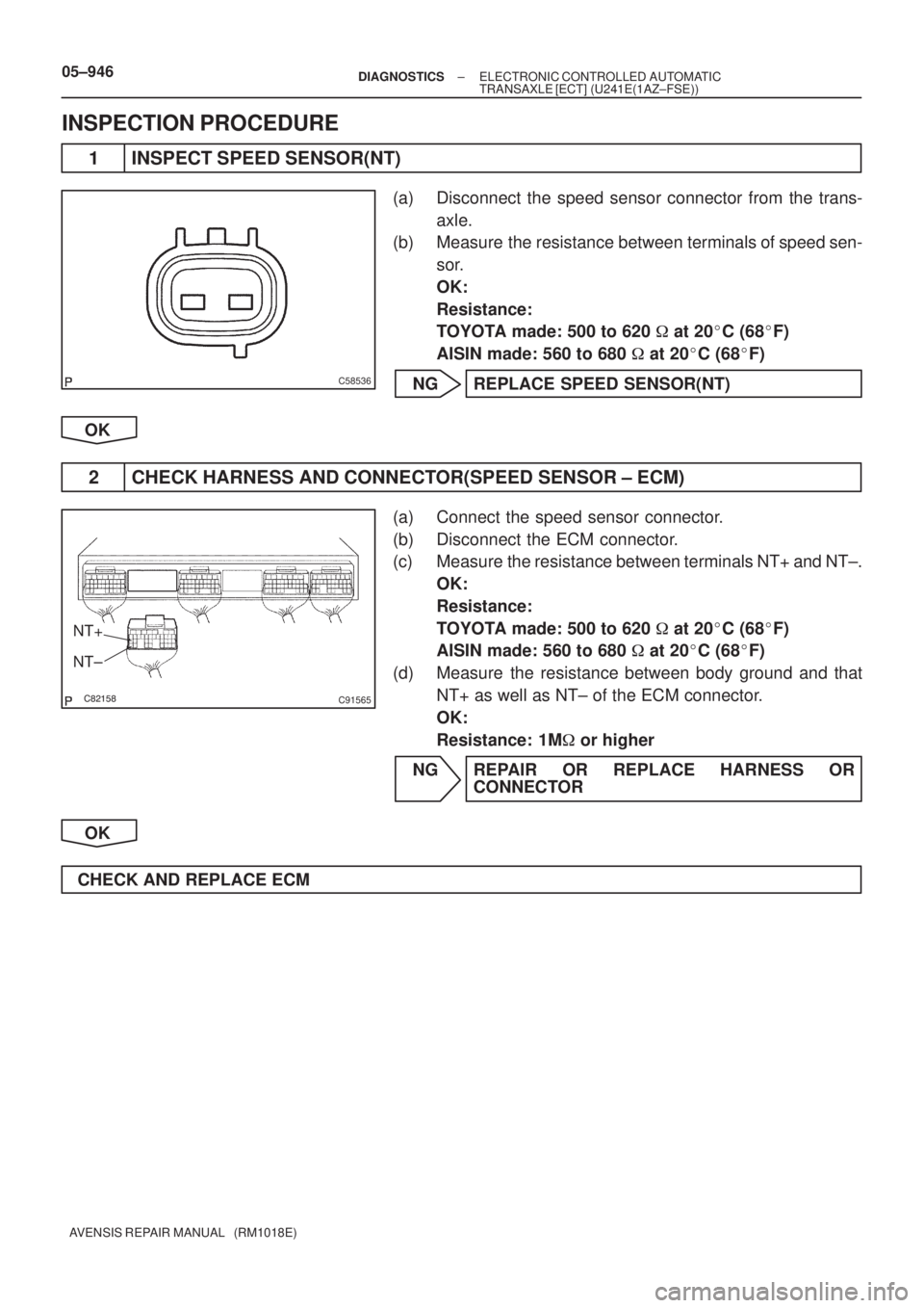
INSPECTION PROCEDURE
1 INSPECT SPEED SENSOR(NT)
(a) Disconnect the speed sensor connector from the trans-
axle.
(b) Measure the resistance between terminals of speed sen-
sor.
OK:
Resistance:
TOYOTA made: 500 to 620 � at 20�C (68�F)
AISIN made: 560 to 680 � at 20�C (68�F)
NG REPLACE SPEED SENSOR(NT)
OK
2 CHECK HARNESS AND CONNECTOR(SPEED SENSOR ± ECM)
(a) Connect the speed sensor connector.
(b) Disconnect the ECM connector.
(c) Measure the resistance between terminals NT+ and NT±.
OK:
Resistance:
TOYOTA made: 500 to 620 � at 20�C (68�F)
AISIN made: 560 to 680 � at 20�C (68�F)
(d) Measure the resistance between body ground and that
NT+ as well as NT± of the ECM connector.
OK:
Resistance: 1M� or higher
NG REPAIR OR REPLACE HARNESS OR
CONNECTOR
OK
CHECK AND REPLACE ECM
)
AVENSIS REPAIR MANUAL (RM1018E)
TRANSMISSION FLUID TEMPERATURE SENSOR NO.2 CIRCUIT
CIRCUIT DESCRIPT](/manual-img/14/57441/w960_57441-969.png "TOYOTA AVENSIS 2005 Service Repair Manual C54864
THOE2
05±900±
DIAGNOSTICS ELECTRONIC CONTROLLED AUTOMATIC
TRANSAXLE [ECT](U241E(1AZ±FE))
AVENSIS REPAIR MANUAL (RM1018E)
TRANSMISSION FLUID TEMPERATURE SENSOR NO.2 CIRCUIT
CIRCUIT DESCRIPT")
![TOYOTA AVENSIS 2005 Service Repair Manual C58536
C95812
NC+
NC±
3
± DIAGNOSTICSELECTRONIC CONTROLLED AUTOMATIC
TRANSAXLE [ECT] (U241E(1AZ±FE))05±893
AVENSIS REPAIR MANUAL (RM1018E)
INSPECTION PROCEDURE
1 INSPECT SPEED SENSOR(NC)
(a) Dis](/manual-img/14/57441/w960_57441-978.png "TOYOTA AVENSIS 2005 Service Repair Manual C58536
C95812
NC+
NC±
3
± DIAGNOSTICSELECTRONIC CONTROLLED AUTOMATIC
TRANSAXLE [ECT] (U241E(1AZ±FE))05±893
AVENSIS REPAIR MANUAL (RM1018E)
INSPECTION PROCEDURE
1 INSPECT SPEED SENSOR(NC)
(a) Dis")