Page 889 of 5135
F45142
Skid Control ECU
with Actuator
SS2
SS1
YGND
YIGA S1 S1 S1 S129
13
16
30
IE83 10
W±G
W±L IE8
W±L J18
J/C
W±G
W±L
W±G
W±L GND
CANL
CANHUBAT
GND CAN
HIGH
12V CAN
LOWB
W (Shielded)
B
W (Shielded)
B
W
(Shielded)
B
W
(Shielded)
B W W±B
W±B (Shielded)1 75
6 4 2 1
3 J6C
B C
B
A
J15
J/C
IK J7E D BD
B
A A B D BJ/C
1
2
9 IE8
J6 J6 J6
J6 J6 J7
J7
J7IE8
IE8
Y1
YAW Rate Sensor
S12
Steering Sensor LHD:
W±G
C
B 05±822
± DIAGNOSTICSABS WITH EBD & BA & TRC & VSC SYSTEM
AVENSIS REPAIR MANUAL (RM1018E)
WIRING DIAGRAM
Page 890 of 5135
F45143
SS2
SS1
YGND
YIGA S1 S1 S1 S1 29
13
16
30
IO112 11
W±G
W±L IO1 W±G
W±L J/C
W±G
W±L
W±G
W±L GND
CANL
CANHUBAT
GND
CAN
HIGH12V CAN
LOWB
W (Shielded)
(Shielded)
B
W
(Shielded)
B
W
W±B1
75
6 4 2 1
3C
B C
B A
J15
J/C
IK B13
12
11
J22 IO2
Y1
YAW Rate Sensor
S12
Steering Sensor RHD:
AJ/C J19
J/C
(Shielded)
B
W
J23
J22
J22
J22 J23 IO2 IO2
C F
C
B
B C
FBSkid Control ECU
with Actuator
± DIAGNOSTICSABS WITH EBD & BA & TRC & VSC SYSTEM
05±823
AVENSIS REPAIR MANUAL (RM1018E)
Page 891 of 5135
05±824
±
DIAGNOSTICS ABS WITH EBD & BA & TRC & VSC SYSTEM
AVENSIS REPAIR MANUAL (RM1018E)
INSPECTION PROCEDURE
1CHECK HARNESS AND CONNECTOR(YAW RATE SENSOR ± SKID CONTROL ECU)
(a)Check for an open or short circuit in harness and connector between the \
yaw rate sensor and skid
control ECU (See page 01±32).
NG REPAIR OR REPLACE HARNESS ORCONNECTOR
OK
2 CHECK HARNESS AND CONNECTOR(STEERING ANGLE SENSOR ± SKID CONTROL ECU)
(a) Check for an open or short circuit in harness and connector between the steer\
ing angle sensor and
skid control ECU (See page 01±32).
NG REPAIR OR REPLACE HARNESS ORCONNECTOR
OK
REPLACE ABS & TRACTION ACTUATOR ASSY(See page 32±57)
Page 894 of 5135
05±818
±
DIAGNOSTICS ABS WITH EBD & BA & TRC & VSC SYSTEM
AVENSIS REPAIR MANUAL (RM1018E)
DTCC1288/88ECU VERSION MISS MATCHI
CIRCUIT DESCRIPTION
DTC No.DTC Detecting ConditionTrouble Area
C1288/88
When either of the following 1 or 2 is detected:
1.ECM does not match.
2.Steering angle sensor is not calibrated.� ECM
� Steering angle sensor calibration.
INSPECTION PROCEDURE
1PERFORM STEERING ANGLE SENSOR ZERO POINT CALIBRATION
(a)Perform the steering angle sensor zero point calibration (See page 05±756).
2 RECONFIRM DTC
(a) Check if the same DTC is stored in the memory.
NO END
YES
3 CHECK HARNESS AND CONNECTOR(STEERING ANGLE SENSOR ± SKID CONTROL ECU)
(a) Check for an open or short circuit in harness and connector between the \
steering angle sensor and
skid control ECU (See page 01±32).
NG REPAIR OR REPLACE HARNESS ORCONNECTOR
OK
REPLACE ABS & TRACTION ACTUATOR ASSY(See page 32±57)
05788±02
Page 898 of 5135

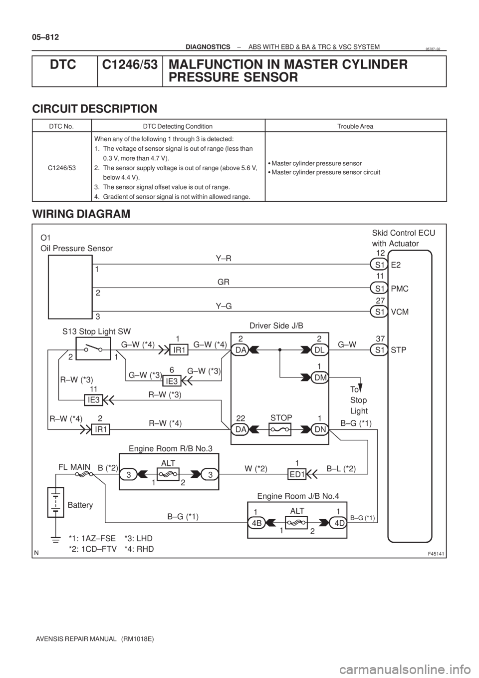
F45141
Skid Control ECU
with Actuator
12
S1
VCM 11
PMC
27E2
S1
S1
STP 37
S1
Battery FL MAIN O1
Oil Pressure Sensor
1
Y±G
1
4B
1
2 2
*1: 1AZ±FSE
*2: 1CD±FTV3
12 33ALT Engine Room R/B No.3
B (*2)
B±G (*1)1
4D Engine Room J/B No.4B±G (*1)
B±L (*2) W (*2) R±W (*3)1 2Y±R
GR
R±W (*4)R±W (*3)
R±W (*4)
11 1 2 2
22DL DA
DA DNDM IR1
6
IE3
11
IE3
2
IR1
ED1 1Driver Side J/B
S13 Stop Light SW
G±W (*3)G±W (*3)G±W (*4) G±W (*4) G±W
To
Stop
Light
B±G (*1)
STOP
*3: LHD
*4: RHDALT 05±812
± DIAGNOSTICSABS WITH EBD & BA & TRC & VSC SYSTEM
AVENSIS REPAIR MANUAL (RM1018E)
DTC C1246/53 MALFUNCTION IN MASTER CYLINDER
PRESSURE SENSOR
CIRCUIT DESCRIPTION
DTC No.DTC Detecting ConditionTrouble Area
C1246/53
When any of the following 1 through 3 is detected:
1. The voltage of sensor signal is out of range (less than
0.3 V, more than 4.7 V).
2. The sensor supply voltage is out of range (above 5.6 V,
below 4.4 V).
3. The sensor signal offset value is out of range.
4. Gradient of sensor signal is not within allowed range.
�Master cylinder pressure sensor
�Master cylinder pressure sensor circuit
WIRING DIAGRAM
05787±02
Page 899 of 5135

±
DIAGNOSTICS ABS WITH EBD & BA & TRC & VSC SYSTEM
05±813
AVENSIS REPAIR MANUAL (RM1018E)
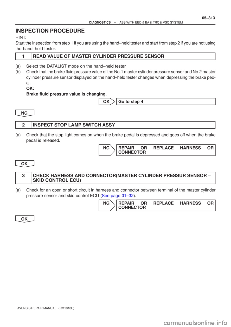
INSPECTION PROCEDURE
HINT:
Start the inspection from step 1 if you are using the hand±held tester and\
start from step 2 if you are not using
the hand±held tester.
1READ VALUE OF MASTER CYLINDER PRESSURE SENSOR
(a)Select the DATALIST mode on the hand±held tester.
(b)Check that the brake fluid pressure value of the No.1 master cylinder pressur\
e sensor and No.2 master
cylinder pressure sensor displayed on the hand±held tester changes wh\
en depressing the brake ped-
al.
OK:
Brake fluid pressure value is changing.
OKGo to step 4
NG
2INSPECT STOP LAMP SWITCH ASSY
(a)Check that the stop light comes on when the brake pedal is depressed and goes\
off when the brake pedal is released.
NGREPAIR OR REPLACE HARNESS ORCONNECTOR
OK
3CHECK HARNESS AND CONNECTOR(MASTER CYLINDER PRESSUR SENSOR ± SKID CONTROL ECU)
(a)Check for an open or short circuit in harness and connector between terminal \
of the master cylinder
pressure sensor and skid control ECU (See page 01±32).
NG REPAIR OR REPLACE HARNESS ORCONNECTOR
OK
Page 905 of 5135
![TOYOTA AVENSIS 2005 Service Repair Manual D26540
T4
Turbine Speed SensorECM
NT+ E1227
B±O
2
B
NT± E1235 1 05±884
± DIAGNOSTICSELECTRONIC CONTROLLED AUTOMATIC
TRANSAXLE [ECT] (U241E(1AZ±FE))
AVENSIS REPAIR MANUAL (RM1018E)
DTC P0717/37 TOYOTA AVENSIS 2005 Service Repair Manual D26540
T4
Turbine Speed SensorECM
NT+ E1227
B±O
2
B
NT± E1235 1 05±884
± DIAGNOSTICSELECTRONIC CONTROLLED AUTOMATIC
TRANSAXLE [ECT] (U241E(1AZ±FE))
AVENSIS REPAIR MANUAL (RM1018E)
DTC P0717/37](/manual-img/14/57441/w960_57441-904.png)
D26540
T4
Turbine Speed SensorECM
NT+ E1227
B±O
2
B
NT± E1235 1 05±884
± DIAGNOSTICSELECTRONIC CONTROLLED AUTOMATIC
TRANSAXLE [ECT] (U241E(1AZ±FE))
AVENSIS REPAIR MANUAL (RM1018E)
DTC P0717/37 TURBINE SPEED SENSOR CIRCUIT NO
SIGNAL
CIRCUIT DESCRIPTION
This sensor detects the rotation speed of the input turbine. By comparing the input turbine speed signal (NT)
with the counter gear speed sensor signal (NC), the ECM detects the shift timing of the gears and appropri-
ately controls the engine torque and hydraulic pressure according to various conditions. Thus smooth gear
shifting is performed.
DTC No.DTC Detection ConditionTrouble Area
P0717/37
ECM detects conditions (a), (b), (c) and (d) continuity for 5 sec.
or more: (2 trip detection logic)
(a) Vehicle speed: 50 km/h (20 mph) or more
(b) 2nd, 3rd or O/D gear
(c) Solenoid valves and park/neutral position switch are normal
(d) NT < 300 rpm
�Open or short in speed sensor (NT) circuit
�Speed sensor (NT)
�ECM
WIRING DIAGRAM
05C8U±01
Page 906 of 5135
C58536
C95812
NT+
NT±
± DIAGNOSTICSELECTRONIC CONTROLLED AUTOMATIC
TRANSAXLE [ECT] (U241E(1AZ±FE))05±885
AVENSIS REPAIR MANUAL (RM1018E)
INSPECTION PROCEDURE
1 INSPECT SPEED SENSOR(NT)
(a) Disconnect the speed sensor connector from the trans-
axle.
(b) Measure the resistance between terminals of speed sen-
sor.
OK:
Resistance:
TOYOTA made: 500 to 620 � at 20�C (68�F)
AISIN made: 560 to 680 � at 20�C (68�F)
NG REPLACE SPEED SENSOR(NT)
OK
2 CHECK HARNESS AND CONNECTOR(SPEED SENSOR ± ECM)
(a) Connect the speed sensor connector.
(b) Disconnect the ECM connector.
(c) Measure the resistance between terminals NT+ and NT±.
OK:
Resistance:
TOYOTA made: 500 to 620 � at 20�C (68�F)
AISIN made: 560 to 680 � at 20�C (68�F)
(d) Measure the resistance between body ground and that
NT+ as well as NT± of the ECM connector.
OK:
Resistance: 1M� or higher
NG REPAIR OR REPLACE HARNESS OR
CONNECTOR
OK
CHECK AND REPLACE ECM