Page 1233 of 5135
05C5V±01
3
2
145678
910111213141516
DLC3
A04550
C93955
05±1184
±
DIAGNOSTICS SUPPLEMENTAL RESTRAINT SYSTEM
AVENSIS REPAIR MANUAL (RM1018E)
PRE±CHECK
1.DIAGNOSIS SYSTEM
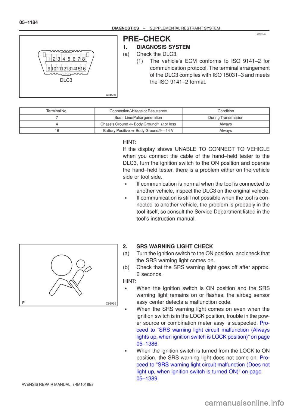
(a)Check the DLC3. (1)The vehicle's ECM conforms to ISO 9141±2 forcommunication protocol. The terminal arrangement
of the DLC3 complies with ISO 15031±3 and meets
the ISO 9141±2 format.
Terminal No.Connection/Voltage or ResistanceCondition
7Bus + Line/Pulse generationDuring Transmission
4Chassis Ground � Body Ground/1 � or lessAlways
16Battery Positive � Body Ground/9 ± 14 VAlways
HINT:
If the display shows UNABLE TO CONNECT TO VEHICLE
when you connect the cable of the hand±held tester to the
DLC3, turn the ignition switch to the ON position and operate
the hand±held tester, there is a problem either on the vehicle
side or tool side.
�If communication is normal when the tool is connected to
another vehicle, inspect the DLC3 on the original vehicle.
�If communication is still not possible when the tool is con-
nected to another vehicle, the problem is probably in the
tool itself, so consult the Service Department listed in the
tool's instruction manual.
2.SRS WARNING LIGHT CHECK
(a)Turn the ignition switch to the ON position, and check that the SRS warning light comes on.
(b)Check that the SRS warning light goes off after approx.
6 seconds.
HINT:
�When the ignition switch is ON position and the SRS
warning light remains on or flashes, the airbag sensor
assy center detects a malfunction code.
�When the SRS warning light comes on even when the
ignition switch is in the LOCK position, trouble in the pow-
er source or combination meter assy is suspected. Pro-
ceed to ºSRS warning light circuit malfunction (Always
lights up, when ignition switch is LOCK position)º on page
05±1386.
�When the ignition switch is turned from the LOCK to ON
position, the SRS warning light does not come on. Pro-
ceed to ºSRS warning light circuit malfunction (Does not
light up, when ignition switch is turned ON)º on page
05±1389.
Page 1234 of 5135
H40173CG
TC
H13050
Normal Code (w/o Past Trouble Code)
Normal Code (w/ Past Trouble Code) Malfunctioning Code
(Example Code 11 and 31) 0.25
ON
OFF
0.750.25
0.25
ON
OFF
0.52.54.0
1.5 0.5 Repeat
DTC31
DTC11
±
DIAGNOSTICS SUPPLEMENTAL RESTRAINT SYSTEM
05±1185
AVENSIS REPAIR MANUAL (RM1018E)
3.DTC CHECK (USING SST CHECK WIRE)
(a)Output the DTCs (Present trouble code).
(1)Turn the ignition switch to the ON position, and wait
for approx. 60 seconds.
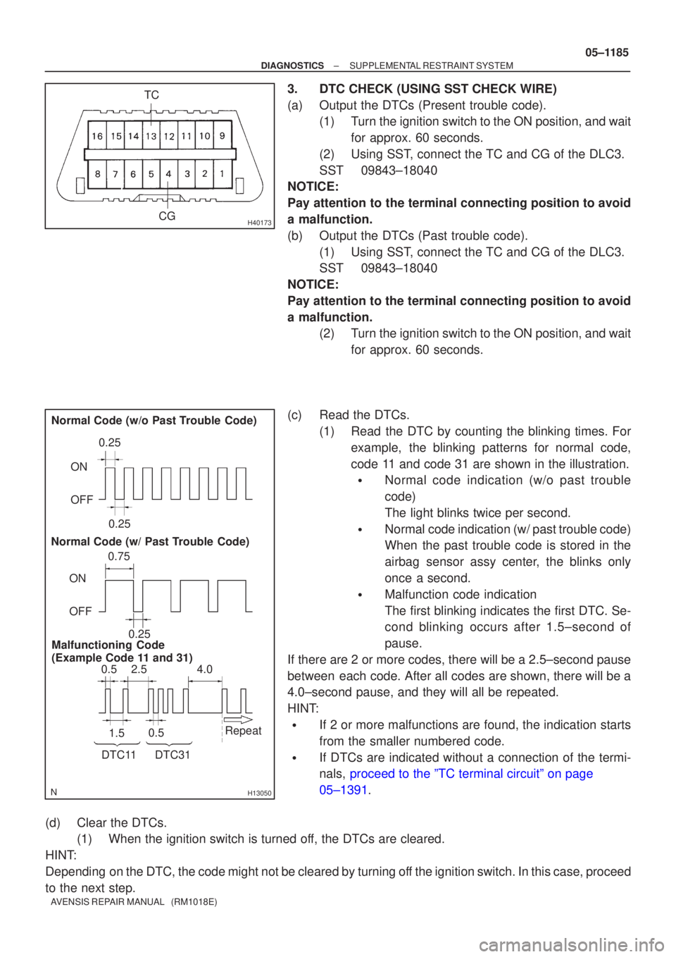
(2)Using SST, connect the TC and CG of the DLC3.
SST09843±18040
NOTICE:
Pay attention to the terminal connecting position to avoid
a malfunction.
(b)Output the DTCs (Past trouble code).
(1)Using SST, connect the TC and CG of the DLC3.
SST09843±18040
NOTICE:
Pay attention to the terminal connecting position to avoid
a malfunction. (2)Turn the ignition switch to the ON position, and wait
for approx. 60 seconds.
(c)Read the DTCs. (1)Read the DTC by counting the blinking times. Forexample, the blinking patterns for normal code,
code 11 and code 31 are shown in the illustration.
�Normal code indication (w/o past trouble
code)
The light blinks twice per second.
�Normal code indication (w/ past trouble code)
When the past trouble code is stored in the
airbag sensor assy center, the blinks only
once a second.
�Malfunction code indication
The first blinking indicates the first DTC. Se-
cond blinking occurs after 1.5±second of
pause.
If there are 2 or more codes, there will be a 2.5±second pause
between each code. After all codes are shown, there will be a
4.0±second pause, and they will all be repeated.
HINT:
�If 2 or more malfunctions are found, the indication starts
from the smaller numbered code.
�If DTCs are indicated without a connection of the termi-
nals, proceed to the ºTC terminal circuitº on page
05±1391.
(d) Clear the DTCs. (1) When the ignition switch is turned off, the DTCs are cleared.
HINT:
Depending on the DTC, the code might not be cleared by turning off the ignition switch. In this case, proceed
to the next step.
Page 1237 of 5135
H42671
Side Airbag
Sensor Assy RH
Airbag Front
RH Sensor
Airbag Sensor
Assy Center
Airbag Sensor
Front LH
Side Airbag
Sensor Assy LH
Airbag Sensor
Rear LH (*1)
Seat Position
Airbag Sensor
(*2)Horn Button Assy
(Squib) Instrument Panel
Passenger Airbag
Assy (Squib)Front Seat Outer
Belt Assy RH
(Squib)
Front Seat
Airbag Assy RH
(Squib)
Front Seat
Airbag Assy
LH (Squib)
Curtain Shield
Airbag Assy LH
(Squib) (*1) Airbag Sensor
Rear RH (*1)Curtain Shield
Airbag Assy RH
(Squib) (*1)
Front Seat Outer
Belt Assy LH
(Squib) Seat Position
Airbag Sensor
(*3)
Instrument Panel
Airbag Assy (Squib)
Spiral Cable
Sub±assy 7
15 8
16
513
614 3 11
412
19
210
23
24 2129
2230
1927
2028
17 25
1826
34 5
6
78
11
12 9
1025
26
27
28
29
30
*1: w/ Curtain Shield Airbag
*2: LHD
*3: RHD 05±1188
± DIAGNOSTICSSUPPLEMENTAL RESTRAINT SYSTEM
AVENSIS REPAIR MANUAL (RM1018E)
Page 1238 of 5135
H42608
Airbag Sensor Assy Center Connector
Short Spring
Before Release After Release
Before Release After Release
Paper
Short Spring
Short Spring Connector
16
Connector
26
20
424
Before Release After Release
Paper
Short Spring Short Spring
PaperPaper
Short Spring
Paper
Paper
± DIAGNOSTICSSUPPLEMENTAL RESTRAINT SYSTEM
05±1189
AVENSIS REPAIR MANUAL (RM1018E)
Page 1250 of 5135
H01454
S18
Side Squib LHAirbag Sensor Assy Center
SFL+
SFL± Y±R
Y±G 1
211 12
A26
A26 05±1238
± DIAGNOSTICSSUPPLEMENTAL RESTRAINT SYSTEM
AVENSIS REPAIR MANUAL (RM1018E)
DTC B0115/47 SHORT IN SIDE SQUIB (LH) CIRCUIT
CIRCUIT DESCRIPTION
The side squib LH circuit consists of the airbag sensor assy center and the separate type front seat back
assy (side squib LH).
This circuit actuates the SRS to deploy when the SRS deployment conditions are fulfilled.
DTC B0115/47 is recorded when a short circuit is detected in the side squib LH circuit.
DTC No.DTC Detecting ConditionTrouble Area
B0115/47
�Short circuit between SFL+ wire harness and SFL± wire har-
ness of side squib LH
�Side squib LH malfunction
�Airbag sensor assy center malfunction�Separate type front seat back assy (Side squib LH)
�Airbag sensor assy center
�Floor wire
WIRING DIAGRAM
056M3±03
Page 1251 of 5135
����� ���\b�H42853
Side Squib LHAirbag
Sensor
Assy
Center
SFL±
SFL+Floor Wire
A
B
C
D
����� ����� ����� ����� ����� �����H42153
Side Squib LH
Airbag
Sensor
Assy
Center
DLC3
CG TC DTC B0115/47
C
D
±
DIAGNOSTICS SUPPLEMENTAL RESTRAINT SYSTEM
05±1239
AVENSIS REPAIR MANUAL (RM1018E)
INSPECTION PROCEDURE
1CHECK FLOOR WIRE(SIDE SQUIB LH CIRCUIT)
(a)Turn the ignition switch to the LOCK position.
(b)Disconnect the negative (±) terminal cable from the bat-
tery, and wait for at least 90 seconds.
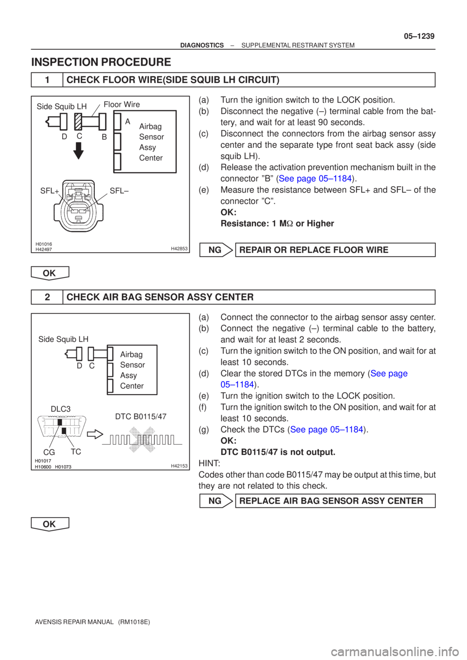
(c)Disconnect the connectors from the airbag sensor assy center and the separate type front seat back assy (side
squib LH).
(d)Release the activation prevention mechanism built in the
connector ºBº (See page 05±1184).
(e) Measure the resistance between SFL+ and SFL± of the connector ºCº.
OK:
Resistance: 1 M � or Higher
NG REPAIR OR REPLACE FLOOR WIRE
OK
2 CHECK AIR BAG SENSOR ASSY CENTER
(a) Connect the connector to the airbag sensor assy center.
(b) Connect the negative (±) terminal cable to the battery, and wait for at least 2 seconds.
(c) Turn the ignition switch to the ON position, and wait for at least 10 seconds.
(d)Clear the stored DTCs in the memory (See page 05±1184).
(e) Turn the ignition switch to the LOCK position.
(f) Turn the ignition switch to the ON position, and wait for at least 10 seconds.
(g)Check the DTCs (See page 05±1184).
OK:
DTC B0115/47 is not output.
HINT:
Codes other than code B0115/47 may be output at this time, but
they are not related to this check.
NG REPLACE AIR BAG SENSOR ASSY CENTER
OK
Page 1252 of 5135
������
������ ������H40988
Side Squib LHDTC B0115/47
DLC3
TC
CG Airbag
Sensor
Assy
Center
C
D
05±1240
±
DIAGNOSTICS SUPPLEMENTAL RESTRAINT SYSTEM
AVENSIS REPAIR MANUAL (RM1018E)
3 CHECK SEPARATE TYPE FRONT SEAT BACK ASSY(SIDE SQUIB LH)
(a) Turn the ignition switch to the LOCK position.
(b) Disconnect the negative (±) terminal cable from the bat- tery, and wait for at least 90 seconds.
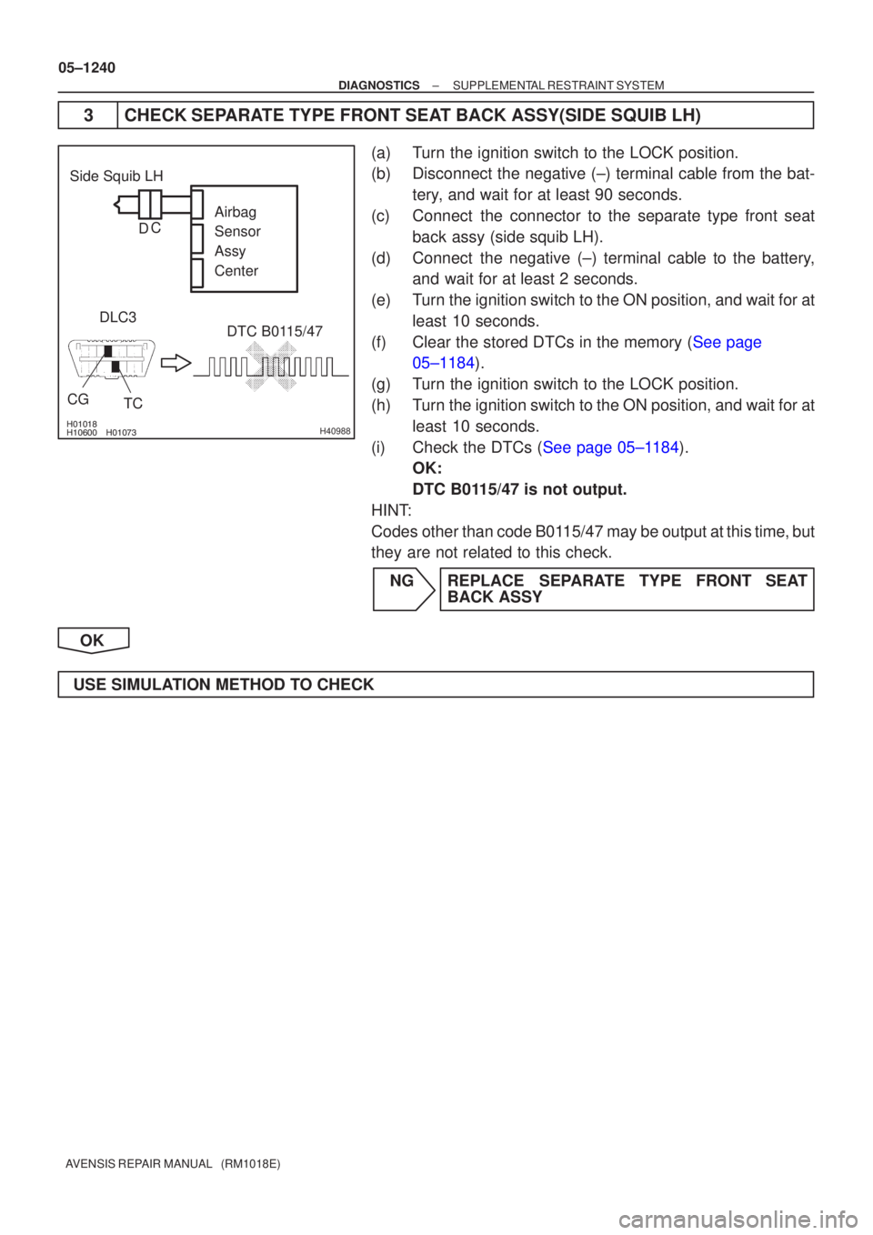
(c) Connect the connector to the separate type front seat back assy (side squib LH).
(d) Connect the negative (±) terminal cable to the battery, and wait for at least 2 seconds.
(e) Turn the ignition switch to the ON position, and wait for at least 10 seconds.
(f)Clear the stored DTCs in the memory (See page 05±1184).
(g) Turn the ignition switch to the LOCK position.
(h) Turn the ignition switch to the ON position, and wait for at least 10 seconds.
(i)Check the DTCs (See page 05±1184). OK:
DTC B0115/47 is not output.
HINT:
Codes other than code B0115/47 may be output at this time, but
they are not related to this check.
NG REPLACE SEPARATE TYPE FRONT SEAT BACK ASSY
OK
USE SIMULATION METHOD TO CHECK
Page 1253 of 5135
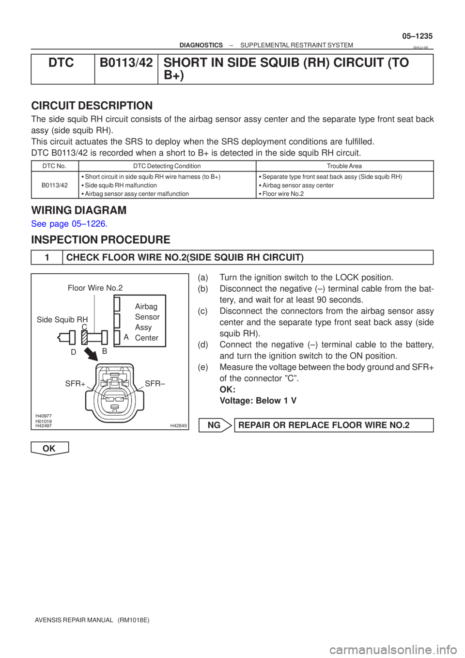
������ ������
������
H42849
Side Squib RHAirbag
Sensor
Assy
Center
SFR±
SFR+
Floor Wire No.2
A
B
C
D
±
DIAGNOSTICS SUPPLEMENTAL RESTRAINT SYSTEM
05±1235
AVENSIS REPAIR MANUAL (RM1018E)
DTC B0113/42 SHORT IN SIDE SQUIB (RH) CIRCUIT (TO
B+)
CIRCUIT DESCRIPTION
The side squib RH circuit consists of the airbag sensor assy center and the\
separate type front seat back
assy (side squib RH).
This circuit actuates the SRS to deploy when the SRS deployment conditio\
ns are fulfilled.
DTC B0113/42 is recorded when a short to B+ is detected in the side squib RH ci\
rcuit.
DTC No.DTC Detecting ConditionTrouble Area
B0113/42
�Short circuit in side squib RH wire harness (to B+)
� Side squib RH malfunction
� Airbag sensor assy center malfunction�Separate type front seat back assy (Side squib RH)
� Airbag sensor assy center
� Floor wire No.2
WIRING DIAGRAM
See page 05±1226.
INSPECTION PROCEDURE
1 CHECK FLOOR WIRE NO.2(SIDE SQUIB RH CIRCUIT)
(a) Turn the ignition switch to the LOCK position.
(b) Disconnect the negative (±) terminal cable from the bat-
tery, and wait for at least 90 seconds.
(c) Disconnect the connectors from the airbag sensor assy center and the separate type front seat back assy (side
squib RH).
(d) Connect the negative (±) terminal cable to the battery,
and turn the ignition switch to the ON position.
(e) Measure the voltage between the body ground and SFR+ of the connector ºCº.
OK:
Voltage: Below 1 V
NG REPAIR OR REPLACE FLOOR WIRE NO.2
OK
054LU±06