Page 1948 of 5135

12±1
AVENSIS REPAIR MANUAL (RM1018E)
EMISSION CONTROL SYSTEM (1ZZ±FE/3ZZ±FE)
ON±VEHICLE INSPE")
1209C±02
A65749
E1
OX1AOX1B
ECM
A66059
± EMISSION CONTROLEMISSION CONTROL SYSTEM (1ZZ±FE/3ZZ±FE)
12±1
AVENSIS REPAIR MANUAL (RM1018E)
EMISSION CONTROL SYSTEM (1ZZ±FE/3ZZ±FE)
ON±VEHICLE INSPECTION
1. INSPECT AIR±FUEL RATIO COMPENSATION SYS-
TEM
HINT:
You can also check the system by choosing ºDATA MONITOR/
O
2 SENSOR OUTPUT VOLTAGEº on the monitor of the hand±
held tester.
(a) Connect the hand±held tester to the terminals 21 (OX1B)
and 7 (E1) and to terminals 23 (OX1A) and 7 (E1) of the
ECM.
CAUTION:
Connect test leads from the back side of the connector with
the ECM connected.
(b) Warm up the heated oxygen sensor with the engine
speed at 2,500 rpm for approximately 2 minutes.
(c) Confirm that the voltage varies output between 0V to 1V
with the engine speed at 2,500 rpm.
OK:
The voltage output varies more than 8 times in 10 se-
conds.
CAUTION:
�Perform the check immediately after the warming up.
�If the voltage variation could not be verified, warm up
the heated oxygen sensor again.
2. INSPECT FUEL CUT OFF RPM
(a) Increase the engine speed to at least 3,500 rpm.
(b) Use a sound scope to check for injector operating sounds.
(c) Check that injector operating sounds stops momentarily and then resumes when the throttle lever is
released.
3. INSPECT EVAPORATIVE EMISSION CONTROL SYS-
TEM
(a) After starting the engine, disconnect the vacuum hose
shown in the illustration.
(b) Check if vacuum occurs at the VSV port when choosing
ºACTIVE TESTº and ºPURGE VSVº according to the dis-
play on hand±held tester.
(c) Finish ºACTIVE TESTº, then reconnect the vacuum.
(d) After entering to ºECU DATA MONITORº on the hand±
held tester, choose ºPURGE VSVº to check the operation
of the purge VSV.
(e) After driving the vehicle with a warm engine, confirm that
the VSV turns from off to on.
Page 1950 of 5135

AVENSIS REPAIR MANUAL (RM1018E)
Removal & Installation and")
110UF±01
A63024
A60575
Quick Connector
O±ring Nylon Tube
Tube Joint Clip
Fuel Suction Plate
A63025
11±104
±
FUEL FUEL TANK ASSY(DIESEL)
AVENSIS REPAIR MANUAL (RM1018E)
Removal & Installation and Disassembly & Reassembly
1.REMOVE REAR SEAT CUSHION ASSY (See page 72±27)
2. REMOVE REAR FLOOR SERVICE HOLE COVER
(a) Remove the 4 screws and the rear floor service hole cover.
(b) Disconnect the connector. 3. DISCONNECT FUEL TANK RETURN TUBE
(a) Remove the tube joint clip and pull out the fuel tank returntube.
NOTICE:
�Check if there is any dirt or mud around the connector
before this operation and remove the dirt as neces-
sary.
�Be careful of mud because the quick connector has
an O±ring which seals the pipe and the connector that
can be contaminated.
�Do not use any tool in this operation.
�Do not bend or twist the nylon tube.
�Keep the plug free of foreign objects.
�To protect the tube, cover it with a vinyl or a plastic
bag after checking.
4. DISCONNECT FUEL TANK MAIN TUBE SUB±ASSY
(a) Pinch the tube connector then pull out the fuel tank main tube.
NOTICE:
�Check if there is any dirt or mud around the connector
before this operation and remove the dirt as neces-
sary.
�Be careful of mud because the quick connector has
an O±ring which seals the pipe and the connector that
can be contaminated.
�Do not use any tool in this operation.
�Do not bend or twist the nylon tube.
�To protect the tube, cover it with a vinyl or a plastic
bag after checking.
�When the connector and the pipe are stuck, push and
pull the connector to release. Pull out the connector
from the pipe carefully.
Page 1951 of 5135

11±105
AVENSIS REPAIR MANUAL (RM1018E)
5.DISCONNECT FUEL EVAPOR ATION TUBE
SUB±ASSY")
A63026
A60576
Fuel Tube
Connector Clip
Nylon Tube
O±ring Pipe
A62989
SST
A77883
±
FUEL FUEL TANK ASSY(DIESEL)
11±105
AVENSIS REPAIR MANUAL (RM1018E)
5.DISCONNECT FUEL EVAPOR ATION TUBE
SUB±ASSY NO.2
(a)Pinch the quick connector then pull out the fuel evapora-
tion tube sub±assy No. 2.
NOTICE:
�Check if there is any dirt or mud around the connector
before this operation and remove the dirt as neces-
sary.
�Be careful of mud because the quick connector has
an O±ring which seals the pipe and the connector that
can be contaminated.
�Do not use any tool in this operation.
�Do not bend or twist the nylon tube.
�To protect the tube, cover it with a vinyl or a plastic
bag after checking.
�When the connector and the pipe are stuck, push and
pull the connector to release. Pull out the connector
from the pipe carefully.
6.REMOVE FUEL AND EVAPORATION VENT TUBE SUB±ASSY
(a)Using SST, loosen the retainer. SST09808±14010
(b)Remove the retainer.
(c)Pull out the fuel pump assembly.
CAUTION:
Be careful that the arm of the sender gauge should not
bent.
7.DRAIN FUEL
8.REMOVE FLOOR PANEL BRACE FRONT (See page 15±10)
9.REMOVE EXHAUST PIPE ASSY FRONT (See page 15±10)
10. REMOVE FUEL TANK PROTECTOR NO.1
(a) Remove the 4 bolts and the fuel tank protector.
Page 1952 of 5135
A77884
A77885
A77886
A77887
A78450
11±106
± FUELFUEL TANK ASSY (DIESEL)
AVENSIS REPAIR MANUAL (RM1018E)
11. REMOVE PARKING BRAKE CABLE ASSY NO.2
(a) Remove the 2 set bolts of the parking brake cable.
12. REMOVE PARKING BRAKE CABLE ASSY NO.3
(a) Remove the 2 set bolts of the parking brake cable.
13. DISCONNECT BREATHER TUBE FUEL HOSE
(a) Loosen the hose clamp and disconnect the fuel tank
breather hose.
14. DISCONNECT FUEL TANK TO FILLER PIPE HOSE
(a) Loosen the hose clamp and disconnect the fuel tank to fill-
er pipe hose.
15. DISCONNECT FUEL TANK RETURN TUBE
Page 1953 of 5135

11±107
AVENSIS REPAIR MANUAL (RM1018E)
16. DISCONNECT FUEL TANK MAIN TUBE SUB±ASS")
A81588
3
1 22
A63387
Retainer Fuel Tube Connector
O±ring
Pipe
A77890
A77894
A78270
± FUELFUEL TANK ASSY (DIESEL)
11±107
AVENSIS REPAIR MANUAL (RM1018E)
16. DISCONNECT FUEL TANK MAIN TUBE SUB±ASSY
(a) Pinch the tab of the retainer to remove the lock claws and
pull down it as shown in the illustration.
(b) Pull out the fuel tank main tube.
NOTICE:
�Check if there is any dirt or mud around the connector
before this operation and remove the dirt as neces-
sary.
�Be careful of mud because the quick connector has
an O±ring which seals the pipe and the connector that
can be contaminated.
�Do not use any tool in this operation.
�Do not bend or twist the nylon tube. Protect the con-
nector by covering it with a vinyl or a plastic bag.
�When the pipe and connector are stuck, push and pull
the connector to release. Pull out the connector from
the pipe carefully.
17. REMOVE FUEL TANK ASSY
(a) Set up a transmission jack under the fuel tank.
(b) Remove the 4 bolts and 2 fuel tank bands, and then re-
move the fuel tank.
18. REMOVE FUEL TANK MAIN TUBE SUB±ASSY
(a) Unfasten the 5 claws, and remove the fuel tank return
tube from the fuel tank.
19. REMOVE FUEL EVAPORATION TUBE SUB±ASSY
NO.2
(a) Unfasten the claw, and remove the fuel evaporation tube
from the fuel tank.
Page 1954 of 5135

AVENSIS REPAIR MANUAL (RM1018E)
20.REMOVE FUEL TANK MAIN TUBE SUB±ASSY
(a)Unfasten the 4 claws, and remov")
A77892
A77893
UpperFuel Tank
Rear
Hose Clamp
A81618
11±108
±
FUEL FUEL TANK ASSY(DIESEL)
AVENSIS REPAIR MANUAL (RM1018E)
20.REMOVE FUEL TANK MAIN TUBE SUB±ASSY
(a)Unfasten the 4 claws, and remove the fuel tank main tube from the fuel tank.
21.INSTALL FUEL TANK MAIN TUBE SUB±ASSY
22.INSTALL FUEL EVAPOR ATION TUBE SUB±ASSY
NO.2
(a)Install the hose clamp as shown in the illustration.
23.INSTALL FUEL TANK RETURN TUBE
24.INSTALL FUEL TANK ASSY Torque: 40 N �m (400 kgf �cm, 29 ft �lbf)
25.CONNECT FUEL TANK MAIN TUBE SUB±ASSY
(a)Push in the fuel tube connector to the pipe, and push up retainer to lock the claws.
NOTICE:
�Check if there is any damage or foreign objects on the connected part.
�After connecting, check if the quick connector and the pipe are securely\
connected by pulling
on them.
26.CONNECT FUEL TANK RETURN TUBE
27.CONNECT FUEL TANK TO FILLER PIPE HOSE
28.CONNECT BREATHER TUBE FUEL HOSE
29.INSTALL PARKING BRAKE CABLE ASSY NO.3 Torque: 5.4 N �m (55 kgf �cm, 48 in. �lbf)
30.INSTALL PARKING BRAKE CABLE ASSY NO.2 Torque: 5.4 N �m (55 kgf �cm, 48 in. �lbf)
31.INSTALL FUEL TANK PROTECTOR NO.1
Torque: 5.4 N �m (55 kgf �cm, 48 in. �lbf)
32.INSTALL EXHAUST PIPE ASSY FRONT (See page 15±10)
33. ADD FUEL
Page 1955 of 5135

11±109
AVENSIS REPAIR MANUAL (RM1018E)
34. INSTALL FUEL AND EVAPORATION VENT TUBE
SUB±ASSY
(a) Align the")
A63379
Mark
A62989
SST
A63380
Area
Arrow
Mark
A64697
A64698
± FUELFUEL TANK ASSY (DIESEL)
11±109
AVENSIS REPAIR MANUAL (RM1018E)
34. INSTALL FUEL AND EVAPORATION VENT TUBE
SUB±ASSY
(a) Align the arrow marks of the fuel pump bracket and the
fuel tank.
(b) Temporarily install the retainer.
(c) Mount SST to the retainer.
SST 09808±14010
(d) Tighten the retainer until the arrow mark located on the re-
tainer is positioned within the area shown in the illustra-
tion.
(e) Check that the arrow marks of the fuel pump bracket and
fuel tank are aligned.
35. CONNECT FUEL EVAPORATION TUBE SUB±ASSY
NO.2
(a) Push in the quick connector to the pipe until connector
makes ºclickº sound.
NOTICE:
�Check if there is any damage or foreign objects on the
connected part of the pipe.
�After connecting, check if the pipe and the connector
are securely connected by pulling on them.
36. CONNECT FUEL TANK MAIN TUBE SUB±ASSY
(a) Push in the quick connector to the pipe until connector
makes ºclickº sound.
NOTICE:
�Check if there is any damage or foreign objects on the
connected part of the pipe.
�After connecting, check if the pipe and the connector
are securely connected by pulling on them.
Page 1956 of 5135
A64699
11±110
±
FUEL FUEL TANK ASSY(DIESEL)
AVENSIS REPAIR MANUAL (RM1018E)
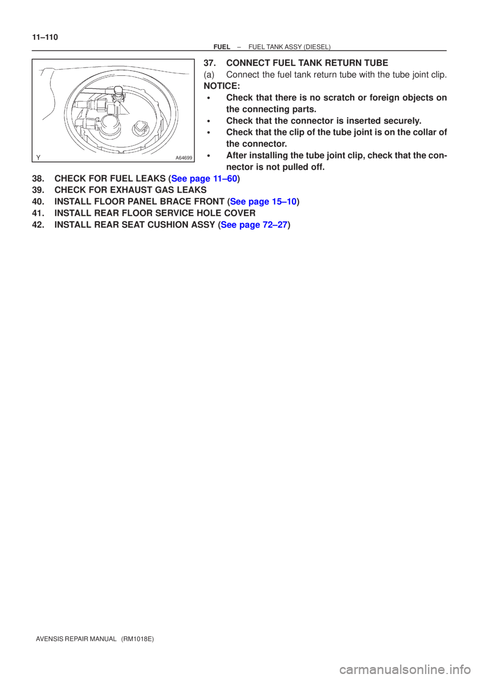
37.CONNECT FUEL TANK RETURN TUBE
(a)Connect the fuel tank return tube with the tube joint clip.
NOTICE:
�Check that there is no scratch or foreign objects on
the connecting parts.
�Check that the connector is inserted securely.
�Check that the clip of the tube joint is on the collar of
the connector.
�After installing the tube joint clip, check that the con-
nector is not pulled off.
38.CHECK FOR FUEL LEAKS (See page 11±60)
39. CHECK FOR EXHAUST GAS LEAKS
40.INSTALL FLOOR PANEL BRACE FRONT (See page 15±10)
41. INSTALL REAR FLOOR SERVICE HOLE COVER
42.INSTALL REAR SEAT CUSHION ASSY (See page 72±27)

AVENSIS REPAIR MANUAL (RM1018E)
11. REMOVE PARKING BRAKE CABLE ASSY NO.2
(a) Remove the 2 set bolts of the parking brake cab")