Page 1916 of 5135

11±75
AVENSIS REPAIR MANUAL (RM1018E)
52.INSTALL TIMING BELT GUIDE(See page 14±307)
53.INSTALL TIMING BELT NO.1 COVER(See page 14±307)
54.INSTALL")
±
FUEL INJECTION OR SUPPLY PUMP ASSY (1CD±FTV)
11±75
AVENSIS REPAIR MANUAL (RM1018E)
52.INSTALL TIMING BELT GUIDE(See page 14±307)
53.INSTALL TIMING BELT NO.1 COVER(See page 14±307)
54.INSTALL TIMING BELT NO.2 COVER(See page 14±307)
55. INSTALL IDLER PULLEY SUB±ASSY
Torque: 40 N �m (408 kgf �cm, 30 ft �lbf)
56.INSTALL CRANKSHAFT PULLEY(See page 14±307) SST 09213±54015 (90105±08076), 09330±00021
57.INSTALL ENGINE MOUNTING INSULATOR SUB±ASSY RH(See page 14±307)
58. INSTALL INJECTOR DRIVER Torque: 5.0 N �m (51 kgf �cm, 44 in. �lbf)
59. ADJUST V (COOLER COMPRESSOR TO CRANKSHAFT PULLEY) BELT NO.1 (See page 14±269)
60.INSTALL RADIATOR RESERVE TANK ASSY(See page 16±50)
61. INSTALL ENGINE COVER NO.1 Torque: 8.0 N �m (82 kgf �cm, 71 in. �lbf)
62.INSTALL AIR CLEANER ASSY (See page 11±60)
63. INSTALL FRONT WHEEL RH
Torque: 103 N �m (1,050 kgf �cm, 76 ft �lbf)
64.ADD ENGINE COOLANT(See page 16±44)
65.CHECK FOR ENGINE COOLANT LEAKS(See page 16±37)
66.CHECK FOR FUEL LEAKS(See page 11±60)
Page 1917 of 5135
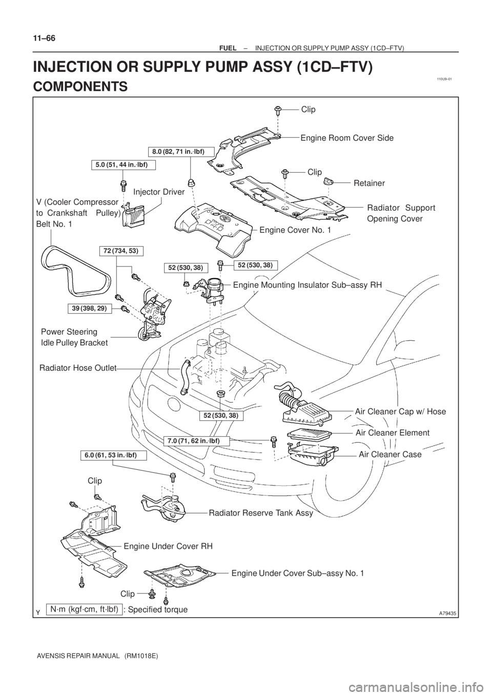
110U9±01
A79435
Air Cleaner Cap w/ Hose
Air Cleaner Element
Air Cleaner Case
7.0 (71, 62 in.�lbf)
N´m (kgf´cm, ft´lbf)
: Specified torque
Radiator Hose Outlet
Clip
Engine Room Cover Side
Clip
Retainer
Radiator Support
Opening Cover
8.0 (82, 71 in.�lbf)
5.0 (51, 44 in.�lbf)
V (Cooler Compressor
to Crankshaft Pulley)
Belt No. 1
Injector Driver
72 (734, 53)
52 (530, 38)52 (530, 38)
Engine Cover No. 1
Engine Mounting Insulator Sub±assy RH
39 (398, 29)
Power Steering
Idle Pulley Bracket
52 (530, 38)
Clip
Engine Under Cover RH
Engine Under Cover Sub±assy No. 1
Clip
Radiator Reserve Tank Assy
6.0 (61, 53 in.�lbf)
11±66
± FUELINJECTION OR SUPPLY PUMP ASSY (1CD±FTV)
AVENSIS REPAIR MANUAL (RM1018E)
INJECTION OR SUPPLY PUMP ASSY (1CD±FTV)
COMPONENTS
Page 1918 of 5135
A61211
: Specified torqueN´m (kgf´cm, ft´lbf)
* Replace only if damagedTiming Belt No. 2 Cover
Transverse Engine
Engine Mounting Bracket
Seal Washer Timing Belt No.1 Cover
Crankshaft Pulley Seal Washer
x 5 Generator V belt
Glow Plug
Screw Grommet Timing Belt GuideTiming Belt * Gasket
x 7
Glow Plug Assy * Gasket Timing Chain Cover Plate
Timing Belt
Tensioner
180 (1,837, 133)
21 (214, 15)
9.0 (92, 80 in.´lbf)
37 (375, 27)
64 (650, 47)
2.2 (22, 19 in.´lbf)
7.4 (76, 66 in.´lbf)
7.4 (76, 66 in.´lbf)
Idler Pulley
40 (408, 30)Glow Plug
No.1 Connector
± FUELINJECTION OR SUPPLY PUMP ASSY (1CD±FTV)
11±67
AVENSIS REPAIR MANUAL (RM1018E)
Page 1919 of 5135
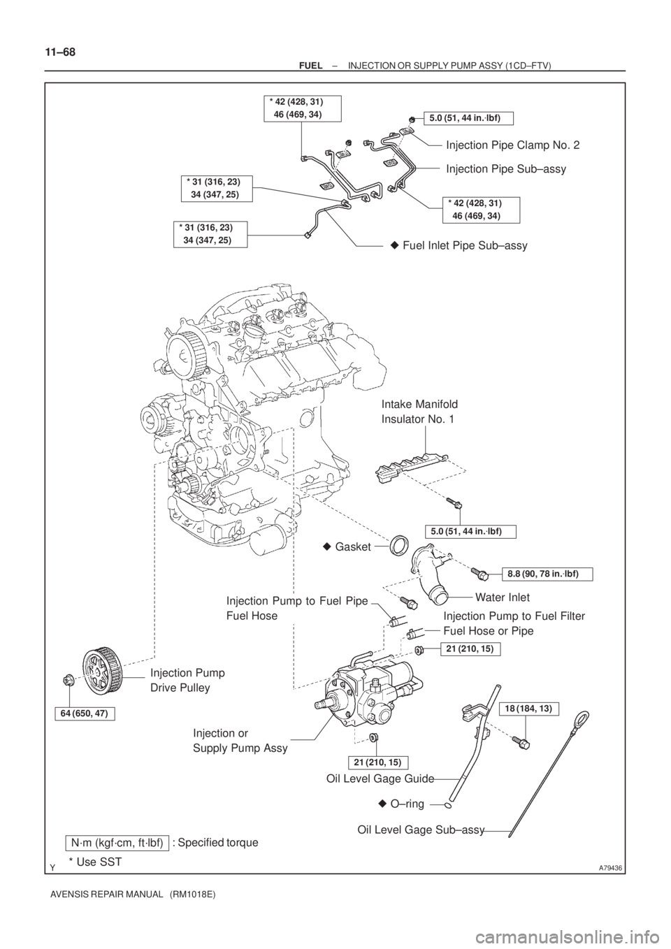
A79436
5.0 (51, 44 in.�lbf)
* 42 (428, 31)
46 (469, 34)
* 31 (316, 23)
34 (347, 25)
* 31 (316, 23)
34 (347, 25)
Injection Pipe Clamp No. 2
Injection Pipe Sub±assy
� Fuel Inlet Pipe Sub±assy
64 (650, 47)
Injection Pump
Drive Pulley
� O±ring Oil Level Gage Guide
: Specified torqueN´m (kgf´cm, ft´lbf)
* Use SST
18 (184, 13)
Oil Level Gage Sub±assy Injection or
Supply Pump Assy
21 (210, 15)
21 (210, 15)
Water Inlet
8.8 (90, 78 in.�lbf)
� Gasket
5.0 (51, 44 in.�lbf)
Intake Manifold
Insulator No. 1
* 42 (428, 31)
46 (469, 34)
Injection Pump to Fuel Filter
Fuel Hose or Pipe
Injection Pump to Fuel Pipe
Fuel Hose
11±68
± FUELINJECTION OR SUPPLY PUMP ASSY (1CD±FTV)
AVENSIS REPAIR MANUAL (RM1018E)
Page 1920 of 5135

AVENSIS REPAIR MANUAL (RM1018E)
REPLACEMENT
HINT:
Each injector assembly has a characteristic fuel injecting behavior. The ECM stores comp")
110U8±01
A79143
SST
11±60
±
FUEL INJECTOR ASSY(1CD±FTV)
AVENSIS REPAIR MANUAL (RM1018E)
REPLACEMENT
HINT:
Each injector assembly has a characteristic fuel injecting behavior. The ECM stores compensation codes
which are used to optimize fuel injection for the injectors. When replacing t\
he injector assembly, a compensa-
tion code for the new injector assembly must be set to the ECM.
1.REMOVE VACUUM RESERVOIR SUB±ASSY
(a)Disconnect the 2 vacuum hoses and the connector.
(b)Remove the 2 bolts and the vacuum reservoir.
2.REMOVE RADIATOR SUPPORT OPENING COVER
3.REMOVE ENGINE COVER NO.1
(a)Remove the 5 nuts and the engine cover.
4.REMOVE AIR CLEANER ASSY
(a)Disconnect the connector.
(b)Remove the air cleaner cap with the air cleaner hose.
(c)Remove the air cleaner filter element.
(d)Remove the 3 bolts and the air cleaner case.
5.REMOVE AIR TUBE NO.1 (See page 14±270) 6. REMOVE INJECTION PIPE SUB±ASSY NO.1
(a) Remove the 2 nuts and 2 upper infection pipe clampsfrom the intake manifold.
(b) Using SST, remove the injection pipe from the common rail side.
SST 09023±12700
(c) Using SST, remove the injection pipe from the injector side.
SST 09023±12700
(d) After removing the fuel pipe, to prevent dust or foreign ob- jects from being introduced, cover the common rail with
vinyl tape and protect the injector inlet with a vinyl or plas-
tic bag.
7. REMOVE INJECTION PIPE SUB±ASSY NO.2
SST 09023±12700
HINT:
Perform the same procedures as injection pipe No. 1.
8. REMOVE INJECTION PIPE SUB±ASSY NO.3 SST 09023±12700
HINT:
Perform the same procedures as injection pipe No. 1.
9. REMOVE INJECTION PIPE SUB±ASSY NO.4 SST 09023±12700
HINT:
Perform the same procedures as injection pipe No. 1.
10. REMOVE TIMING BELT NO.2 COVER
(a) Remove the 7 bolts and 7 seal washers, then remove the timing belt cover\
.
Page 1921 of 5135

11±61
AVENSIS REPAIR MANUAL (RM1018E)
11.REMOVE NOZZLE HOLDER SEAL
(a)Using a screwdriver, pry out the 4 nozzle holder seals.
12.REMOVE CYLINDER")
A09656
A79144
A80110
±
FUEL INJECTOR ASSY(1CD±FTV)
11±61
AVENSIS REPAIR MANUAL (RM1018E)
11.REMOVE NOZZLE HOLDER SEAL
(a)Using a screwdriver, pry out the 4 nozzle holder seals.
12.REMOVE CYLINDER HEAD COVER SUB±ASSY
(a)Remove the 10 bolts and the cylinder head cover.
13.REMOVE NOZZLE LEAKAGE PIPE ASSY
(a)Remove the union bolt and the 4 hollow screws, then re-
move the nozzle leakage pipe and the 5 gaskets.
NOTICE:
When removing then nozzle leakage pipe, place the shop
rag under the pipe to protect the cylinder head from the fuel
remaining inside the pipe.
14.REMOVE NOZZLE HOLDER CLAMP
(a)Remove the 4 bolts, 4 washers and 4 nozzle holder clamps.
15.REMOVE INJECTOR ASSY
(a)Remove the 4 injectors from the cylinder head.
(b)Remove the O±rings and back±up rings from each injector.
(c)Remove the 4 nozzle seats from the cylinder head.
16.REGISTRATION OF INJECTOR COMPENSATION CODE (See page 05±528)
HINT:
Each injector assembly has a characteristic fuel injecting behavior. When replacing the injector assembly,
store them in correct order so that they can be returned to the original\
locations when re±assembling. 17. INSTALL INJECTOR ASSY
(a) Install 4 new nozzle seats to the cylinder head.
Page 1922 of 5135

AVENSIS REPAIR MANUAL (RM1018E)
(b) Install new back±up rings and O±rings to each injector.
(c) Apply a li")
A79187
O±ringBack±up ring
B08249
A80111
180�
90� 11±62
± FUELINJECTOR ASSY (1CD±FTV)
AVENSIS REPAIR MANUAL (RM1018E)
(b) Install new back±up rings and O±rings to each injector.
(c) Apply a light coat of engine oil onto the O±rings on each
injector.
(d) Install the injector to the cylinder head.
NOTICE:
Fit the injectors to the nozzle seat.
(e) Install the nozzle holder clamp as shown in the illustration.
Tighten the camshaft bearing cap bolt by hand to fix the
nozzle holder clamp.
NOTICE:
�Pay attention to the mounting orientation of the wash-
er.
�When temporarily attaching the nozzle holder clamp
and the mounting bolt, be careful not to orient them
at an angle.
HINT:
Apply a light coat of engine oil on the threads of the nozzle hold-
er clamp bolts.
(f) Install the injection pipe No. 1, No. 2, No. 3 and No. 4,
tighten the nuts by hand.
(g) Install new 5 gaskets and the leakage pipe No. 1. Tighten
the 4 hollow screws by hand.
(h) Tighten the 4 nozzle holder clamp bolts.
Torque: 26 N�m (265 kgf�cm, 19 ft�lbf)
(i) Remove the 4 injection pipes.
18. INSTALL NOZZLE LEAKAGE PIPE ASSY
(a) Install the nozzle leakage pipe and 5 new gaskets.
NOTICE:
When installing the gaskets, pay attention to the mounting
orientation. Install the gasket so that the joint portion of the
gasket comes within the ranges shown in the illustration.
(b) Apply a light coat of oil onto the 4 hollow screws and the
union bolt.
(c) Tighten the 4 hollow screws and the union bolt by hand.
(d) Tighten the 4 hollow screws and the union bolt.
Torque:
18 N�m (184 kgf�cm, 13 ft�lbf) for hollow screw
22 N�m (224 kgf�cm, 16 ft�lbf) for union bolt
(e) Check that there are no leaks from the nozzle leakage
pipe connection.
(1) Disconnect the fuel hose, and remove the bolt, the
check valve and the nozzle leakage No. 2 pipe and
the gasket.
Page 1923 of 5135
")
A80119
New Gasket
Hollow
Screw
Union
Bolt
SST
Nozzle Leakage
No. 2 Pipe
New Gasket
SST
A79146
Check
Valve
Nozzle Leakage
No. 2 Pipe
New Gasket
A09663
:Seal Packing
± FUELINJECTOR ASSY (1CD±FTV)
11±63
AVENSIS REPAIR MANUAL (RM1018E)
(2) Install the bolt, the nozzle leakage No. 2 pipe and
the gasket to the cylinder head with SST.
SST 09280±00010
Torque:
8.8 N�m (90 kgf�cm, 79 in.�lbf) for bolt
21 N�m (214 kgf�cm, 15 ft�lbf) for SST
(3) Apply a light coat of soapy water (any fluid to detect
fuel leakage) on the nozzle leakage pipe No. 2 con-
nection.
(4) Using SST (turbocharger pressure gauge), attach
SST to the fuel return side of the nozzle leakage No.
2 pipe, and maintain 100 kPa (1.0 kgf/cm
2, 14.5 psi)
of pressure for 60 seconds to check that there are
no bubbles from the pipe connection.
SST 09992±00242
(5) After checking fuel leaks, wipe off soapy water from
the pipe connection.
(6) Remove 2 SSTs, and then remove the bolt, the
nozzle leakage No.2 pipe and the gasket.
(7) Place a new gasket and reinstall the nozzle leakage
No. 2 pipe with the check valve and the bolt.
Torque:
8.8 N�m (90 kgf�cm, 79 in.�lbf) for bolt
21 N�m (214 kgf�cm, 15 ft�lbf) for check valve
HINT:
Do not disassemble the check valve on the engine.
(8) Reconnect the fuel hose to the nozzle leakage No.
2 pipe.
19. INSTALL CYLINDER HEAD COVER SUB±ASSY
(a) Remove any old packing (FIPG) material.
(b) Apply seal packing to the cylinder head.
Seal packing: Part No. 08826±00080 or equivalent
(c) Install the gasket to the cylinder head cover.
(d) Install the cylinder head cover with the 10 bolts.
Torque: 13 N�m (135 kgf�cm, 9.7 ft�lbf)

* Replace only if damagedTiming Belt No. 2 Cover
Transverse Engine
Engine Mounting Bracket
Seal Washer Timing Belt No.1 Cover
Crankshaft Pulley Seal W")