Page 1892 of 5135

AVENSIS REPAIR MANUAL (RM1018E)
(b)Apply a light coat of spindle oil or gasoline on the place whe")
A77913
Turn
Push
A77914
Turn
A81621
Fuel Pipe
Clamp
Push
11±28
±
FUEL FUEL INJECTOR ASSY(1AZ±FE)
AVENSIS REPAIR MANUAL (RM1018E)
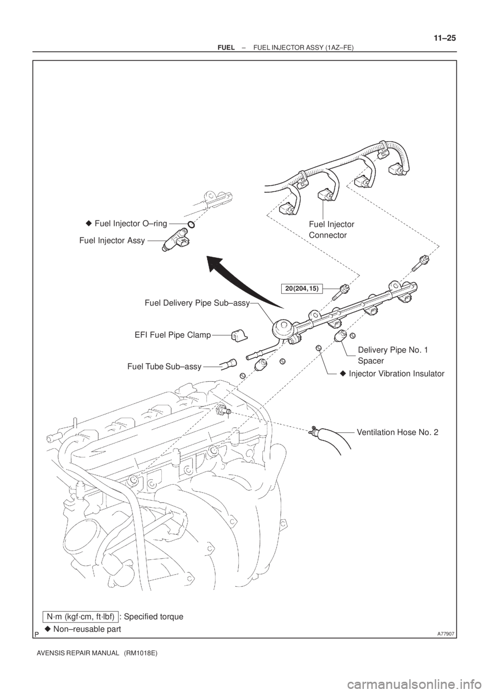
(b)Apply a light coat of spindle oil or gasoline on the place where a fuel delivery pipe contacts the O±ring.
(c)Push the fuel injector while twisting it back and forth to
install it to the fuel delivery pipe.
NOTICE:
�Be careful not to twist the O±ring.
�After installing the fuel injectors, check that they turn
smoothly. If not, reinstall it with a new O±ring.
8.INSTALL FUEL DELIVERY PIPE SUB±ASSY
(a)Install 4 new insulators and the 2 delivery pipe No. 1 spacers to the cylinder head.
(b)Place the fuel delivery pipe and the 4 fuel injectors togeth- er to the cylinder head.
NOTICE:
Be careful not to drop the fuel injectors when installing the
fuel delivery pipe.
(c)Temporarily install 2 bolts which are used to secure the fuel delivery pipe to the cylinder head.
(d)Check that the fuel injectors rotate smoothly.
If the fuel injectors do not rotate smoothly, the probable cause
is incorrect installation of O±ring. Replace with the O±ring.
(e)Tighten the 2 bolts. Torque: 20 N �m (204 kgf �cm, 15 ft �lbf)
(f)Connect the 4 fuel injector connectors.
(g)Install the 2 wire harness clamps.
(h)Connect the ventilation hose.
9.CONNECT FUEL TUBE SUB±ASSY
(a)Push in the connector to the pipe until it makes ºclickº sound.
NOTICE:
�Check if there is any damage or foreign objects on the
connected part.
�After connecting, check if the connector and the pipe
are securely connected by pulling on them.
(b)Install the fuel pipe clamp.
10.INSTALL AIR CLEANER CAP SUB±ASSY
11.CHECK FOR FUEL LEAKS (See page 11±19)
12.INSTALL ENGINE COVER SUB±ASSY NO.1 (See page 10±26)
Page 1893 of 5135
110U0±01
A79730
Mass Air Flow
Meter Connector
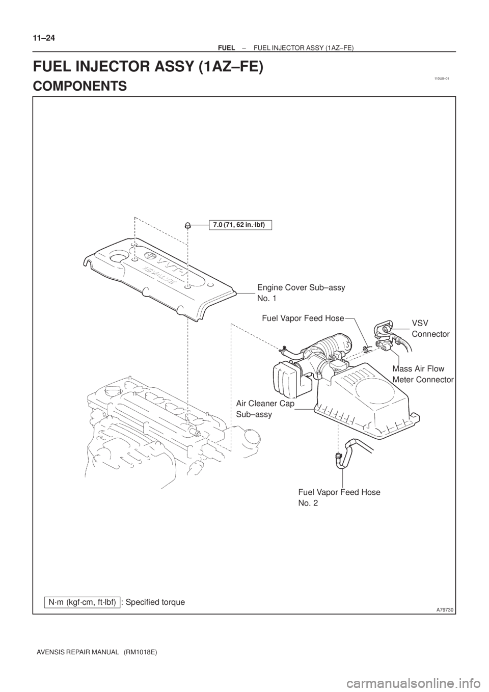
N´m (kgf´cm, ft´lbf) : Specified torqueEngine Cover Sub±assy
No. 1
7.0 (71, 62 in.�lbf)
Fuel Vapor Feed Hose
No. 2
Air Cleaner Cap
Sub±assyVSV
Connector Fuel Vapor Feed Hose
11±24
± FUELFUEL INJECTOR ASSY (1AZ±FE)
AVENSIS REPAIR MANUAL (RM1018E)
FUEL INJECTOR ASSY (1AZ±FE)
COMPONENTS
Page 1894 of 5135
A77907� Non±reusable part
N´m (kgf´cm, ft´lbf) : Specified torque
20 (204, 15)
Fuel Injector
Connector
EFI Fuel Pipe Clamp
Fuel Tube Sub±assy
� Injector Vibration InsulatorDelivery Pipe No. 1
Spacer Fuel Delivery Pipe Sub±assy
Ventilation Hose No. 2
Fuel Injector Assy� Fuel Injector O±ring
± FUELFUEL INJECTOR ASSY (1AZ±FE)
11±25
AVENSIS REPAIR MANUAL (RM1018E)
Page 1895 of 5135

B12947
SST (Hose)SST
(Clamp)
Vinyl Tube SST (Union)
O±Ring
A51875
11±22
±
FUEL FUEL SYSTEM(1AZ±FE)
AVENSIS REPAIR MANUAL (RM10")
110UY±01
Fuel Tube Connector
A50710
Fuel Tube Connector
SST
(Hose)
B12947
SST (Hose)SST
(Clamp)
Vinyl Tube SST (Union)
O±Ring
A51875
11±22
±
FUEL FUEL SYSTEM(1AZ±FE)
AVENSIS REPAIR MANUAL (RM1018E)
INSPECTION
1.INSPECT FUEL INJECTOR ASSY
(a)Inspect injector resistance (1)Using an ohmmeter, measure the resistance be-tween the terminals.
Resistance: 13.4 to 14.2 �at 20 �C (68 �F)
If the resistance is not as specified, replace the injector.
(b)Inspect injector inspection
CAUTION:
This test involves high±pressure fuel and electricity. Take
every precaution regarding safe handling of both the fuel
and the electricity. Preform this test in a safe area, and
avoid any sparks or flame. Do not smoke.
(1)Obtain new No. 1 fuel pipe (part No. 23901±0H040)and remove the fuel tube connector from the pipe.
(2)Install the fuel tube connector to SST (hose), then connect the tube connector and the fuel pipe.
SST09268±41047 (95336±08070)
CAUTION:
Connect the fuel tube connector (quick type) after observ-
ing the precautions to prevent fuel from spraying.
(3)Install the O±ring to the injector.
(4)Connect SST (union and hose) to the injector, andhold the injector and the union with SST (clamp)
SST09268±41047 (09268±41110, 09268±41300, 95336±08070)
(5)Put the injector into a graduated cylinder.
CAUTION:
Install a suitable vinyl tube onto the injector to contain gas-
oline spray. (6)Operate the fuel pump.(See Page 11±19)
Page 1896 of 5135

11±23
AVENSIS REPAIR MANUAL (RM1018E)
(7) Connect SST (wire) to the injector and the battery
for 15 seconds, and measure the injection v")
SST
A50700
B00069
A16628A32859
± FUELFUEL SYSTEM (1AZ±FE)
11±23
AVENSIS REPAIR MANUAL (RM1018E)
(7) Connect SST (wire) to the injector and the battery
for 15 seconds, and measure the injection volume
with a graduated cylinder. Test each injector 2 or 3
times.
SST 09842±30080
Injection volume:
Injection volumeDifference between each injector
60 to 73 cm3
(3.6 to 4.5 cu in.)
in 15 seconds13 cm3 (0.9 cu in.) or less
NOTICE:
Always do the switching at the battery side.
If the injection volume is not as specified, replace the injector.
(c) Inspect leakage
(1) In the condition above, disconnect the test probes
of SST (wire) from the battery and check the fuel
leakage from the injector.
Fuel drop: 1 drop or less in 12 minutes
2. INSPECT FUEL PUMP
(a) Insect fuel pump resistance.
(1) Using an ohmmeter, measure the resistance be-
tween the terminals.
Resistance: 0.2 to 3.0 � at 20�C (68�F)
(b) Inspect fuel pump operation
(1) Apply battery voltage to both the terminals. Check
that the pump operates.
NOTICE:
�These tests must be done quickly (within 10 seconds)
to prevent damage to the pump.
�Keep fuel pump as far away from the battery as pos-
sible.
�Always do the switching at the battery side.
Page 1897 of 5135

A78443
1
2
Tube Joint Clip
A60575
Nylon Tube
Fuel Tube Joint
O±ring Tube Joint Clip
Fuel Suction Plate
±
FUEL FUEL PUMP ASSY(GASOLINE)
11±85
AVENSIS REPAIR MANUAL (RM1018E)
R")
110U4±01
A78442
(a)
A78443
1
2
Tube Joint Clip
A60575
Nylon Tube
Fuel Tube Joint
O±ring Tube Joint Clip
Fuel Suction Plate
±
FUEL FUEL PUMP ASSY(GASOLINE)
11±85
AVENSIS REPAIR MANUAL (RM1018E)
REPLACEMENT
1.DISCHARGE FUEL SYSTEM PRESSURE
HINT:
�1ZZ±FE/3ZZ±FE: 11±1
�1AZ±FE: 11±15
�1AZ±FSE: 11±30
2.REMOVE REAR SEAT CUSHION ASSY (SEAT FIXED TYPE) (See page 72±32)
3. REMOVE REAR FLOOR SERVICE HOLE COVER
(a) Remove the 4 screws, and then remove the rear floor ser-vice hole cover.
(b) Disconnect the fuel pump connector.
4. DISCONNECT FUEL TANK RETURN TUBE (1AZ±FSE ENGINE TYPE)
(a) Remove the tube joint clip, and pull out the fuel return tube.
NOTICE:
�Check if there is any dirt or mud around the connector
before this operation and remove the dirt as neces-
sary.
�Be careful of mud because the fuel tube joint has an
O±ring which seals the pipe and connector that can
be contaminated.
�Do not use any tool in this operation.
�Do not bend or twist the nylon tube. Protect the con-
nector by covering it with a vinyl or plastic bag.
�When the pipe and connector are stuck, push and pull
the connector to release and pull the connector out
carefully.
Page 1898 of 5135

A78444
2
1
Pinch1
Pinch
A75650
Tube Connector
Pipe O±ring Nylon Tube
A78445
2
Pinch
Pinch1
1
A65059
Nylon TubeO±ringFuel Tube
Connector Clip
Fuel Tube
ConnectorPipe
A78446
SST
Rib
11±86
± FUELFUEL PUMP ASSY (GASOLINE)
AVENSIS REPAIR MANUAL (RM1018E)
5. DISCONNECT FUEL TANK MAIN TUBE SUB±ASSY
(a) Pinch the tube connector and pull out the fuel tank main
tube.
NOTICE:
�Check if there is any dirt or mud around the connector
before this operation and remove the dirt as neces-
sary.
�Be careful of mud because the quick connector has
an O±ring which seals the pipe and connector that
can be contaminated.
�Do not use any tool in this operation.
�Do not bend or twist the nylon tube. Protect the con-
nector by covering it with a vinyl or plastic bag.
�When the pipe and connector are stuck, push and pull
the connector to release and pull the connector out
carefully.
6. DISCONNECT FUEL EVAPORATION TUBE
SUB±ASSY NO.2
(a) Pinch the fuel tube connector clip and pull out the fuel
evaporation tube.
NOTICE:
�Check if there is any dirt or mud around the connector
before this operation and remove the dirt as neces-
sary.
�Be careful of mud because the quick connector has
an O±ring which seals the pipe and connector that
can be contaminated.
�Do not use any tool in this operation.
�Do not bend or twist the nylon tube. Protect the con-
nector by covering it with a vinyl or plastic bag.
�When the pipe and connector are stuck, push and pull
the connector to release and pull the connector out
carefully.
7. REMOVE FUEL SUCTION W/PUMP & GAGE TUBE
ASSY
(a) Using SST, loosen the fuel pump gauge retainer.
SST 09808±14010
NOTICE:
Do not use other tools in this operation. Damage to the fuel
pump gauge retainer and the fuel tank may result.
HINT:
A rib on the fuel pump gauge retainer can be fitted into a tip of
the SST.
Page 1899 of 5135

11±87
AVENSIS REPAIR MANUAL (RM1018E)
(b) Remove the fuel pump gauge retainer.
(c) Remove the")
A78447
A78448
Triangle Mark
Matchmark
A78446
SST
Rib
A78449
Arrow Mark
± FUELFUEL PUMP ASSY (GASOLINE)
11±87
AVENSIS REPAIR MANUAL (RM1018E)
(b) Remove the fuel pump gauge retainer.
(c) Remove the fuel suction w/ pump & gage tube.
NOTICE:
Be careful that the arm of the fuel sender gage should not
be bent.
(d) Remove the gasket from the tank.
8. INSTALL FUEL SUCTION W/PUMP & GAGE TUBE
ASSY
(a) Install a new gasket to the fuel tank.
(b) Install the fuel suction w/ pump & gage tube.
NOTICE:
Be careful that the arm of the fuel sender gage should not
be bent.
(c) Align the triangle mark of the fuel suction w/ pump & gage
tube with the matchmark location the fuel tank.
(d) Temporarily install the fuel pump gauge retainer.
(e) Using SST, tighten the fuel pump gauge retainer until the
arrow mark is aligned with the center mark on the fuel
tank.
SST 09808±14010
NOTICE:
Do not use other tools in this operation. Damage to the fuel
pump gauge retainer and the fuel tank may result.
HINT:
A rib on the fuel pump gauge retainer can be fitted into a tip of
the SST.
(f) Check that the arrow mark and center mark are aligned
as shown in the illustration.