Page 1876 of 5135
11±48
±
FUEL FUEL INJECTOR ASSY(1AZ±FSE)
AVENSIS REPAIR MANUAL (RM1018E)
26.INSTALL THROTTLE BODY ASSY (See page 10±44)
27.INSTALL AIR CLEANER CAP SUB±ASSY (See page 10±44)
28.ADD ENGINE COOLANT (See page 16±31)
29.CHECK FOR ENGINE COOLANT LEAKS (See page 16±25)
30. CHECK FOR FUEL LEAKS
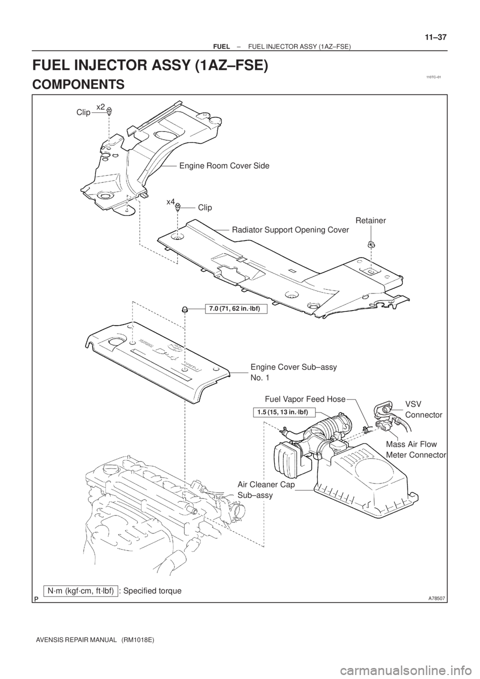
31. INSTALL ENGINE COVER SUB±ASSY NO.1 Torque: 7.0 N �m (71 kgf �cm, 62 in. �lbf)
32. INSTALL ENGINE ROOM COVER SIDE
33. INSTALL RADIATOR SUPPORT OPENING COVER
Page 1877 of 5135
110TC±01
A78507
Mass Air Flow
Meter Connector
N´m (kgf´cm, ft´lbf) : Specified torqueEngine Cover Sub±assy
No. 1
7.0 (71, 62 in.�lbf)
Air Cleaner Cap
Sub±assyVSV
Connector Fuel Vapor Feed Hose
Clip
Engine Room Cover Side
Radiator Support Opening Cover
Clip
Retainer
x2
x4
1.5 (15, 13 in.�lbf)
± FUELFUEL INJECTOR ASSY (1AZ±FSE)
11±37
AVENSIS REPAIR MANUAL (RM1018E)
FUEL INJECTOR ASSY (1AZ±FSE)
COMPONENTS
Page 1878 of 5135
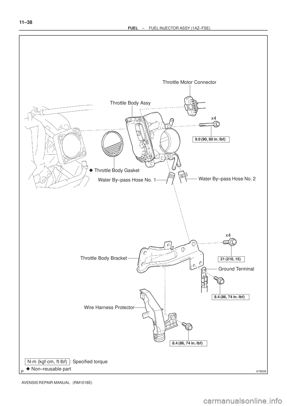
A78508� Non±reusable part
N´m (kgf´cm, ft´lbf) : Specified torqueThrottle Body AssyThrottle Motor Connector
� Throttle Body Gasket
Water By±pass Hose No. 2
Water By±pass Hose No. 1
9.0 (90, 80 in.�lbf)
x4
x4
21 (210, 15)Throttle Body Bracket
8.4 (86, 74 in.�lbf)
Ground Terminal
Wire Harness Protector
8.4 (86, 74 in.�lbf)
11±38
± FUELFUEL INJECTOR ASSY (1AZ±FSE)
AVENSIS REPAIR MANUAL (RM1018E)
Page 1879 of 5135
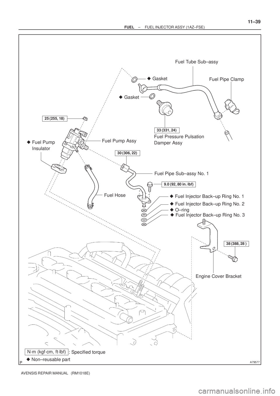
A79577
N´m (kgf´cm, ft´lbf)
: Specified torque
� Non±reusable part� Gasket� GasketFuel Tube Sub±assy
Fuel Pipe Clamp
Fuel Pressure Pulsation
Damper Assy Fuel Pump Assy
� Fuel Pump
Insulator
Fuel HoseFuel Pipe Sub±assy No. 1
� Fuel Injector Back±up Ring No. 1
25 (255, 18)
33 (331, 24)
9.0 (92, 80 in.�lbf)
38 (388, 28 )
30 (306, 22)
� Fuel Injector Back±up Ring No. 2
� Fuel Injector Back±up Ring No. 3 � O±ring
Engine Cover Bracket
± FUELFUEL INJECTOR ASSY (1AZ±FSE)
11±39
AVENSIS REPAIR MANUAL (RM1018E)
Page 1880 of 5135
A79597
N´m (kgf´cm, ft´lbf)
: Specified torque
� Non±reusable part� Gasket� Gasket
38 (388, 28)
21 (210, 15)
9.5 (97, 84 in.�lbf)
30 (306, 22)
9.8 (100, 7)
30 (306, 22)
30 (306, 22)
Union to Connector
Tube Hose
Vacuum Hose
Intake Manifold
Insulator No. 1
Intake Air Control Valve Assy
Intake Manifold Insulator No. 2
Surge Tank
Stay No. 1
Engine Cover Bracket
Charcoal Canister Assy
Intake Manifold
x2 11±40
± FUELFUEL INJECTOR ASSY (1AZ±FSE)
AVENSIS REPAIR MANUAL (RM1018E)
Page 1881 of 5135
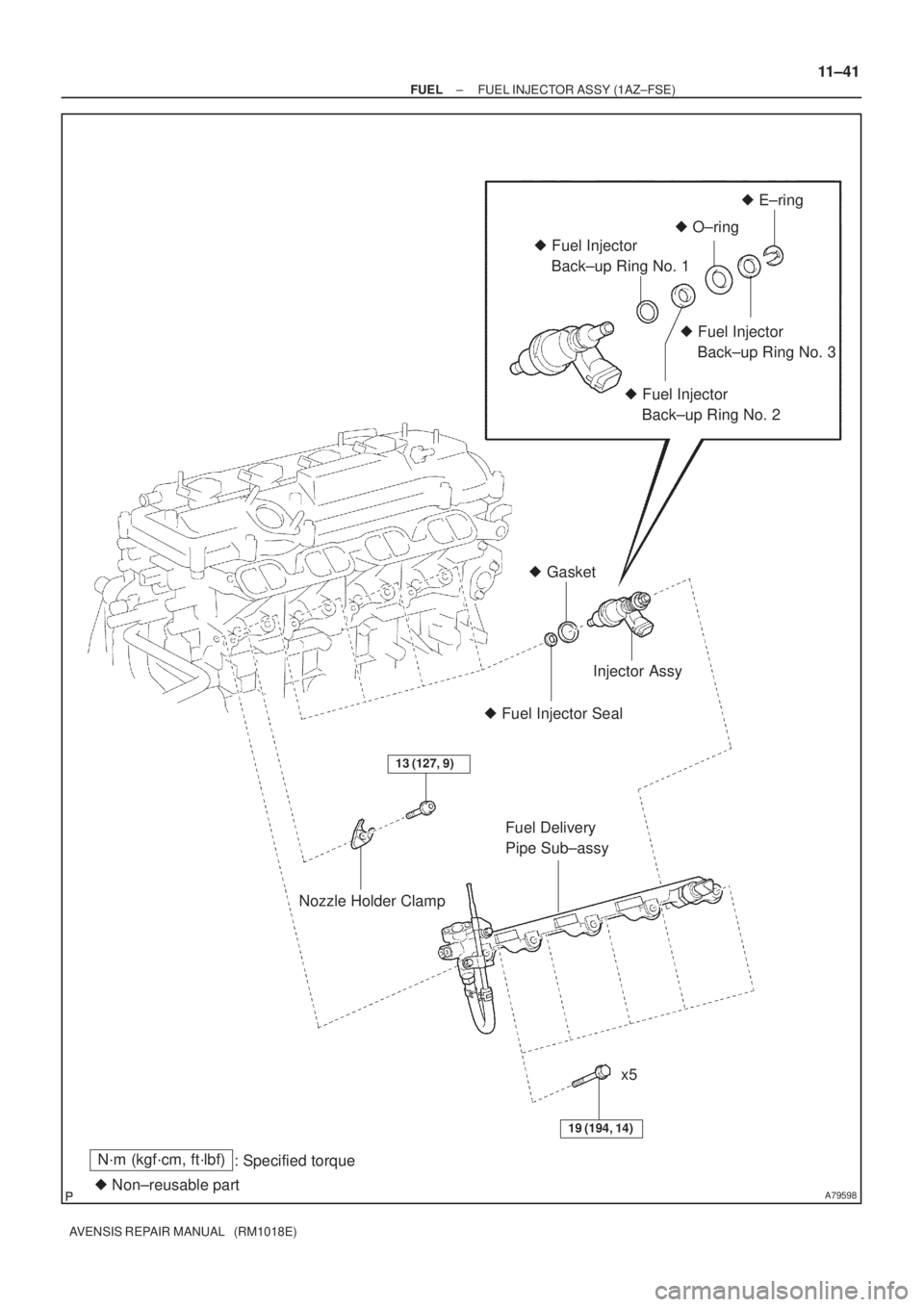
A79598
N´m (kgf´cm, ft´lbf)
: Specified torque
� Non±reusable part� Fuel Injector Seal� Gasket
13 (127, 9)
19 (194, 14)
� O±ring� E±ring
� Fuel Injector
Back±up Ring No. 3
� Fuel Injector
Back±up Ring No. 2 � Fuel Injector
Back±up Ring No. 1
Injector Assy
Fuel Delivery
Pipe Sub±assy
Nozzle Holder Clamp
x5
± FUELFUEL INJECTOR ASSY (1AZ±FSE)
11±41
AVENSIS REPAIR MANUAL (RM1018E)
Page 1882 of 5135

AVENSIS REPAIR MANUAL (RM1018E)
INSPECTION
1. INSPECT FUEL INJECTOR ASSY
NOTICE:
This inspection aims at inspecting the fu")
110V1±01
A16628A32859
B10599
Ohmmeter 11±36
± FUELFUEL SYSTEM (1AZ±FSE)
AVENSIS REPAIR MANUAL (RM1018E)
INSPECTION
1. INSPECT FUEL INJECTOR ASSY
NOTICE:
This inspection aims at inspecting the fuel injectors for open or short, because the fuel injectors of
this vehicle are high±pressure type and do not allow to inspect fuel injection volume.
(a) Inspect injector resistance
(1) Using an ohmmeter, measure the resistance between the terminals.
Resistance: 2.55 to 2.85�at 20�C (68�F)
If the resistance is not as specified, replace the injector.
2. INSPECT FUEL PUMP
(a) Insect fuel pump resistance.
(1) Using an ohmmeter, measure the resistance be-
tween the terminals.
Resistance: 0.2 to 3.0 � at 20�C (68�F)
(b) Inspect fuel pump operation
(1) Apply battery voltage to both the terminals. Check
that the pump operates.
NOTICE:
�These tests must be done quickly (within 10 seconds)
to prevent damage to the pump.
�Keep fuel pump as far away from the battery as pos-
sible.
�Always do the switching at the battery side.
3. INSPECT FUEL PUMP (HIGH PRESSURE)
(a) Remove the engine cover.
(b) Disconnect the fuel pump connector.
(c) Using an ohmmeter, measure the resistance between the
terminals.
Resistance: 1.19 to 1.39 � at 20�C (68�F)
If the resistance is not as specified, replace the fuel pump.
(d) Reconnect the connector.
(e) Reinstall the engine cover.
Page 1883 of 5135

11±33
AVENSIS REPAIR MANUAL (RM1018E)
ON±VEHICLE INSPECTION
1.CHECK FUEL PRESSURE
(a)Disch")
110V0±01
Fuel Tube Connector
A50710
A60083
Fuel Pipe
Clamp No.1
AA
B12941
±
FUEL FUEL SYSTEM(1AZ±FSE)
11±33
AVENSIS REPAIR MANUAL (RM1018E)
ON±VEHICLE INSPECTION
1.CHECK FUEL PRESSURE
(a)Discharge the pressure in the fuel system and take pre-
cautions for possible fuel spillage. (See page 11±30)
(b) Check that the battery voltage is above 12 V.
(c) Disconnect the negative (±) battery cable.
(d) Pull out the connecter from a new fuel tube.
HINT:
Part No. 23901±28160
(e) Disconnect the fuel tube clamp from the fuel tube connec- tor.
(f) Disconnect the fuel tube connector from the fuel pipe while pinching part A with fingers as shown in the illustra-
tion.
CAUTION:
�Do not disconnect the fuel tube connector (quick
type) until after you have discharged the fuel system
pressure and taken appropriate steps to prevent fuel
spillage.
�There may be remained pressure in the fuel lines after
discharging the pressure.
Take precautions to prevent fuel from spraying on
you or your clothing or inside the engine compart-
ment.

AVENSIS REPAIR MANUAL (RM1018E)
26.INSTALL THROTTLE BODY ASSY (See page 10±44)
27.INSTALL AIR CLEANER CAP SUB±ASSY (See page 10±44)
28.ADD ENGINE COOLA")