Page 1854 of 5135

SST (T joint)SST
SST
(Hose)
B12975
11±6
± FUELFUEL SYSTEM (1ZZ±FE/3ZZ±FE)
AVENSIS REPAIR MANUAL (RM1018E)
(g) Install SST (pressure gauge) and a fue")
No.1 Fuel Pipe
Fuel Tube Connector
SST
(Clip)
SST (T joint)SST
SST
(Hose)
B12975
11±6
± FUELFUEL SYSTEM (1ZZ±FE/3ZZ±FE)
AVENSIS REPAIR MANUAL (RM1018E)
(g) Install SST (pressure gauge) and a fuel tube connector
using SST as shown in the illustration.
SST 09268±41047(95336±08070),09268±45014
(09268±41250, 09268±41200, 09268±41220)
(h) Wipe up any gasoline.
(i) Reconnect the negative (±) battery cable.
(j) Connect the hand±hand tester to the DLC3.
(k) Measure the fuel pressure.
Fuel pressure:
304 to 343 kPa (3.1 to 3.5 kgf/cm
2, 44 to 50 psi)
If pressure is high, replace the fuel pressure regulator.
If pressure is low, check the fuel hoses connections, the fuel
pump, the fuel filter and the fuel pressure regulator.
(l) Disconnect the hand±held tester from the DLC3.
(m) Start the engine.
(n) Measure the fuel pressure at idle.
Fuel pressure:
304 to 343 kPa (3.1 to 3.5 kgf/cm
2, 44 to 50 psi)
(o) Stop the engine.
(p) Check that the fuel pressure remains as specified for 5
minutes after the engine has stopped.
Fuel pressure:147 kPa (1.5 kgf/cm
2, 21 psi) or more
If pressure is not as specified, check the fuel pump, the pres-
sure regulator and/or the injectors.
(q) After checking the fuel pressure, disconnect the negative
(±) battery cable and carefully remove SST and the fuel
tube connector to prevent gasoline from splashing.
(r) Reconnect the No. 1 fuel pipe (fuel tube connector).
CAUTION:
After taking the precautions, connect the fuel tube con-
necter (quick type).
2. CHECK FUEL PUMP OPERATION AND FUEL LEAK
(a) When using the hand±held tester
(1) Connect the hand±held tester to the DLC3.
(2) Turn the ignition switch ON and the hand±held tes-
ter main switch ON.
NOTICE:
Do not start the engine.
(3) Select the active test mode on the hand±held tester.
(4) Perform the active test. Check that the fuel pump
operates and check for fuel leaks.
Page 1855 of 5135
A75342
Battery4
5
± FUELFUEL SYSTEM (1ZZ±FE/3ZZ±FE)
11±7
AVENSIS REPAIR MANUAL (RM1018E)
(b) When not using the hand±held tester
(1) Connect the positive (+) lead form the battery to ter-
minal 4 of the connector and connect the negative
(±) lead to terminal 5.
(2) Check that the pump operates.
Page 1856 of 5135

11±1
AVENSIS REPAIR MANUAL (RM1018E)
FUEL SYSTEM(1ZZ±FE/3ZZ±FE)
PRECAUTION
1.PRECAUTION
(a)Be")
110UT±01
A75341
Fuel
Pump
Connector
B00679
Vinyl or Plastic Bag
±
FUEL FUEL SYSTEM(1ZZ±FE/3ZZ±FE)
11±1
AVENSIS REPAIR MANUAL (RM1018E)
FUEL SYSTEM(1ZZ±FE/3ZZ±FE)
PRECAUTION
1.PRECAUTION
(a)Before working on fuel system, disconnect negative (±) battery cable.
(b)Do not smoke or work near fire when handling the fuel system.
(c)Keep gasoline away from rubber or leather parts.
2.DISCHARGE FUEL SYSTEM PRESSURE
CAUTION:
�Do not disconnect any part of the fuel system until
you have discharged the fuel system pressure.
�Even after discharging the fuel pressure, place a
shop rag over fittings as you separate them to reduce
risk of fuel spray on yourself or in the engine compart-
ment.
(a)Disconnect the fuel pump connector.
(b)Start the engine. After the engine has stopped, turn the ignition switch OFF.
(c)Disconnect the negative (±) battery cable.
(d)Connect the fuel pump connector.
3.FUEL SYSTEM
(a)When disconnecting the high fuel pressure line, a large amount of gasoline will spill out, so observe these proce-
dures.
(1)Discharge the pressure in the fuel system. (See step 2)
(2) Disconnect the fuel pump tube. (See page 11±93)
(3) Drain the fuel that remained inside the fuel pump tube.
(4) Cover the disconnected fuel pump tubes with a vinyl or a plastic bag to prevent damage and dirt.
(5) Place a tray under the vehicle or point of disconnec-
tion to catch any fuel that may spill.
Page 1857 of 5135

O±ring
Delivery Pipe InjectorCORRECT
WRONG
B10707
A75345
Delivery Pipe
InsulatorGrommetO±ring
Insulator
Delivery Pipe
O±ring
1ZZ±FE
3ZZ±FE
O±ring
Retainer Pipe
Nylon Tube
Housing
A50709
A75344
Fuel Pipe Clamp No.2
11±2
± FUELFUEL SYSTEM (1ZZ±FE/3ZZ±FE)
AVENSIS REPAIR MANUAL (RM1018E)
(b) Observe the following precautions when removing and
installing fuel injectors.
NOTICE:
Never reuse the O±ring.
(1) When installing a new O±ring on the injector, be
careful not to damage the injector.
(2) Coat the new O±ring with grease or gasoline before
installing. Never use engine oil, gear oil or brake oil.
(c) Install the injector to the delivery pipe and cylinder head
as shown in the illustration. Before installing the injector,
be sure to apply grease or gasoline on the place where
the delivery pipe contacts the O±ring of the injector.
(d) Observe these precautions when disconnecting the fuel
delivery pipe.
HINT:
The structure of the metallic connector is as shown in the il-
lustration on the left.
(1) Remove the fuel pipe clamp No.2.
(2) Find the metallic connector of the fuel tube assem-
bly, slide it towards the vehicle rear and hold it as
it is.
Page 1858 of 5135

Insert
A50705
A60083
Fuel Pipe
Clamp No.1
A
A
B12941
B12944
± FUELFUEL SYSTEM (1ZZ±FE/3ZZ±FE)
11±3
AVENSIS REPAIR MANUAL (RM1018E)
(3) Assemble SST to the")
A60818
SST
SST
Retainer
(at 4 places)
Insert
A50705
A60083
Fuel Pipe
Clamp No.1
A
A
B12941
B12944
± FUELFUEL SYSTEM (1ZZ±FE/3ZZ±FE)
11±3
AVENSIS REPAIR MANUAL (RM1018E)
(3) Assemble SST to the connection of fuel pipe as
shown in the illustration.
SST 09268±21010
(4) Turn SST, align the retainers inside the connector
with SST chamfered parts and insert SST into the
connector.
(5) Slide SST and the connector together towards the
fuel tube assembly.
(e) Observe these following precautions when disconnecting
the fuel tube connector (quick type).
(1) Remove the fuel pipe clamp No.1.
(2) Check that there is no dirt or mud on the pipe and
around the connector before disconnecting them.
Clean them if necessary.
(3) Disconnect the connector from the hose while
pinching part A with fingers as shown in the illustra-
tion.
(4) When the connector and the pipe are stuck, push
and pull the connector to release and pull the con-
nector out from the pipe carefully.
(5) Inspect that there is no dirt or mud on the sealing
surface of the disconnected pipe. Clean it away if
necessary.
Page 1859 of 5135
A82344
Vinyl Bag or plastic Bag
B16534Push
B16535Pull
11±4
±
FUEL FUEL SYSTEM(1ZZ±FE/3ZZ±FE)
AVENSIS REPAIR MANUAL (RM1018E)
(6)To prevent the disconnected pipe and connector from being damaged and foreign objects from being
introduced, cover them with a vinyl or plastic bag.
(f)Observe these precautions when connecting the fuel tube connectors (Quick Type):
(1)Check that there is no damage or foreign objects in
the connected part of the pipe.
(2)Match the axis of the connector with the axis of the pipe, and push into the connector until the connec-
tor makes a ºclickº sound. If the connection is tight,
apply little amount of fresh engine oil on the tip of the
pipe.
(3)After having finished the connection, check if the
pipe and the connector are securely connected by
pulling on them.
(4)Check for fuel leaks.
4.CHECK FOR FUEL LEAKS
(a)Check that there are no fuel leaks after doing maintenance anywhere on t\
he fuel system. (See page 11±5)
Page 1861 of 5135
100FR±01
A79186
±
ENGINE CONTROL SYSTEM ECM
10±65
AVENSIS REPAIR MANUAL (RM1018E)
ECM
REPLACEMENT
HINT:
1CD±FTV Engine Type:
Each injector assembly has a characteristic fuel injecting behavior. The ECM stores compensation codes
which are used to optimize fuel injection for the injectors. When replacing t\
he ECM, the compensation codes
must be set to the new ECM.
1.REMOVE GLOVE COMPARTMENT DOOR ASSY (See page 71±11)
2.REMOVE ECM
(a)Disconnect the 4 ECM connectors (1ZZ±FE, 3ZZ±FE,1AZ±FE, 1CD±FTV).
(b)Disconnect the 5 ECM connectors (1AZ±FSE).
(c)Disconnect the wire harness clamp.
(d)Remove the bolt and screw, then remove the ECM.
(e)Remove the 2 screws and the ECM bracket No. 1 from the ECM.
(f)Remove the 2 screws and the ECM bracket No. 2 from the ECM.
3.INSTALL ECM Torque: 5.5 N �m (56 kgf �cm, 49 in. �lbf)
4.INSTALL GLOVE COMPARTMENT DOOR ASSY (See page 71±11)
5.REGISTRATION OF INJECTOR COMPENSATION CODE (1CD±FTV ENGINE TYPE) (See page 05±528)
Page 1867 of 5135
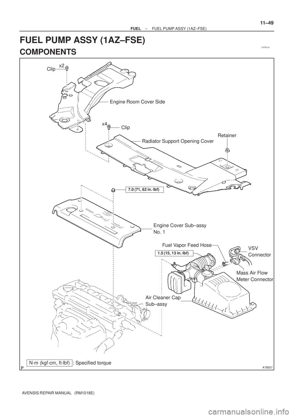
110TA±01
A78507
Mass Air Flow
Meter Connector
N´m (kgf´cm, ft´lbf) : Specified torqueEngine Cover Sub±assy
No. 1
7.0 (71, 62 in.�lbf)
Air Cleaner Cap
Sub±assyVSV
Connector Fuel Vapor Feed Hose
Clip
Engine Room Cover Side
Radiator Support Opening Cover
Clip
Retainer
x2
x4
1.5 (15, 13 in.�lbf)
± FUELFUEL PUMP ASSY (1AZ±FSE)
11±49
AVENSIS REPAIR MANUAL (RM1018E)
FUEL PUMP ASSY (1AZ±FSE)
COMPONENTS

11±7
AVENSIS REPAIR MANUAL (RM1018E)
(b) When not using the hand±held tester
(1) Connect the positive (+) lead form the battery to ter-
mina")

AVENSIS REPAIR MANUAL (RM1018E)
(6)To prevent the disconnected pipe and connector from being damaged")

ECM
REPLACEMENT
HINT:
1CD±FTV Engine Type:
Each injector assembly has a characteristic fuel injecting behavior.")