Page 1786 of 5135
100FG±01
A77870
Mass Air Flow
Meter Connector
N´m (kgf´cm, ft´lbf) : Specified torqueEngine Cover Sub±assy
No. 1
7.0 (71, 62 in.�lbf)
Fuel Vapor Feed Hose
No. 2
Air Cleaner Cap
Sub±assyVSV
Connector Fuel Vapor Feed Hose
Clip
Engine Room Cover Side
Radiator Support Opening Cover
Clip
Retainer
x2
x4 10±24
± ENGINE CONTROL SYSTEMTHROTTLE BODY ASSY (1AZ±FE)
AVENSIS REPAIR MANUAL (RM1018E)
THROTTLE BODY ASSY (1AZ±FE)
COMPONENTS
Page 1787 of 5135
A77871� Non±reusable part
N´m (kgf´cm, ft´lbf) : Specified torqueISC Valve
� ISC Valve Gasket
Fuel Vapor Feed HoseThrottle Position Sensor
Accelerator Control Cable
Assy
� Throttle Body Gasket
Water By±pass Hose No. 2Water By±pass HoseFuel Tube Sub±assy Fuel Pipe Support Throttle Position Sensor
Connector ISC Valve Connector
13 (129, 9)30 (306, 22)
Throttle Body Assy
± ENGINE CONTROL SYSTEMTHROTTLE BODY ASSY (1AZ±FE)
10±25
AVENSIS REPAIR MANUAL (RM1018E)
Page 1797 of 5135
100FD±01
A78454
N´m (kgf´cm, ft´lbf) : Specified torqueClip
Cylinder Head Cover No.2
Fuel
Vapor Feed Hose No.1
VSV
Connector
Mass Air Flow
Meter Connector Accelerator Control
Cable Assy
Fuel Vapor Feed Hose
No.3 Engine Room Cover Side
Radiator Support Opening Cover
Clip
Retainer
7.0 (71, 62 in.´lbf)
Clip
1.5 (15, 13 in.´lbf)
13 (129, 9)
Air Cleaner Cap
Sub±assy
x2
x4
± ENGINE CONTROL SYSTEMTHROTTLE BODY ASSY (3ZZ±FE)
10±13
AVENSIS REPAIR MANUAL (RM1018E)
THROTTLE BODY ASSY (3ZZ±FE)
COMPONENTS
Page 1800 of 5135

A78460
(a)
(b)(c)
(c)
(d)
(e)
(f)
(g)
(h)
Air Cleaner clamp
A78461
A78462
(a)
(b)
(c)
A78463
(d)
(e)
(M/T) 10±10
± ENGINE CONTROL SYSTEMTHROTTLE BODY ASSY (1ZZ±FE)
AVENSIS REPAIR MANUAL (RM1018E)
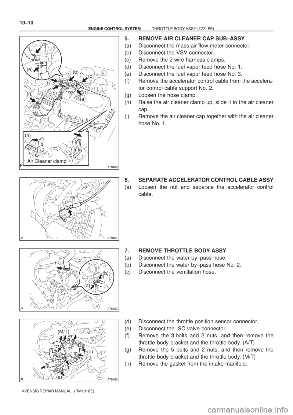
5. REMOVE AIR CLEANER CAP SUB±ASSY
(a) Disconnect the mass air flow meter connector.
(b) Disconnect the VSV connector.
(c) Remove the 2 wire harness clamps.
(d) Disconnect the fuel vapor feed hose No. 1.
(e) Disconnect the fuel vapor feed hose No. 3.
(f) Remove the accelerator control cable from the accelera-
tor control cable support No. 2.
(g) Loosen the hose clamp.
(h) Raise the air cleaner clamp up, slide it to the air cleaner
cap.
(i) Remove the air cleaner cap together with the air cleaner
hose No. 1.
6. SEPARATE ACCELERATOR CONTROL CABLE ASSY
(a) Loosen the nut and separate the accelerator control
cable.
7. REMOVE THROTTLE BODY ASSY
(a) Disconnect the water by±pass hose.
(b) Disconnect the water by±pass hose No. 2.
(c) Disconnect the ventilation hose.
(d) Disconnect the throttle position sensor connector.
(e) Disconnect the ISC valve connector.
(f) Remove the 3 bolts and 2 nuts, and then remove the
throttle body bracket and the throttle body. (A/T)
(g) Remove the 5 bolts and 2 nuts, and then remove the
throttle body bracket and the throttle body. (M/T)
(h) Remove the gasket from the intake manifold.
Page 1803 of 5135
100FB±01
A78454
N´m (kgf´cm, ft´lbf) : Specified torqueClip
Cylinder Head Cover No.2
Fuel
Vapor Feed Hose No.1
VSV
Connector
Mass Air Flow
Meter Connector Accelerator Control
Cable Assy
Fuel Vapor Feed Hose
No.3 Engine Room Cover Side
Radiator Support Opening Cover
Clip
Retainer
7.0 (71, 62 in.´lbf)
Clip
1.5 (15, 13 in.´lbf)
13 (129, 9)
Air Cleaner Cap
Sub±assy
x2
x4
± ENGINE CONTROL SYSTEMTHROTTLE BODY ASSY (1ZZ±FE)
10±7
AVENSIS REPAIR MANUAL (RM1018E)
THROTTLE BODY ASSY (1ZZ±FE)
COMPONENTS
Page 1810 of 5135

������������
30
20
10
5
3
02040 0.11
0.3
0.2 0.52
60 80 100 ±20
(±4) (104) (140) (176)(32) (68) (212)
Z17274
Ohmmeter
Acceptable
Temperature �C (�F)
Resistance k�
THF E2
A30331
30
20
10
�
�
�
�
0.5
0.3
0.2
0.1
±20�
20 4060
80 100
F14741(±4) (104) (140) (176)(32) (68) (212)
A56276
Temperature �C (�F)
Resistance k�
± ENGINE CONTROL SYSTEMECD SYSTEM (1CD±FTV)
10±57
AVENSIS REPAIR MANUAL (RM1018E)
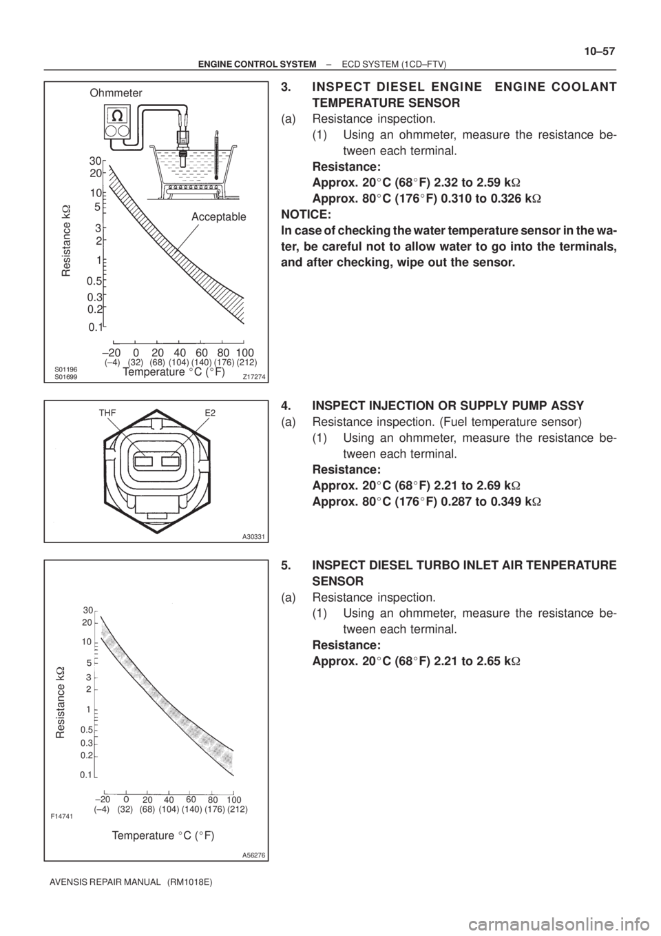
3. INSPECT DIESEL ENGINE ENGINE COOLANT
TEMPERATURE SENSOR
(a) Resistance inspection.
(1) Using an ohmmeter, measure the resistance be-
tween each terminal.
Resistance:
Approx. 20�C (68�F) 2.32 to 2.59 k�
Approx. 80�C (176�F) 0.310 to 0.326 k�
NOTICE:
In case of checking the water temperature sensor in the wa-
ter, be careful not to allow water to go into the terminals,
and after checking, wipe out the sensor.
4. INSPECT INJECTION OR SUPPLY PUMP ASSY
(a) Resistance inspection. (Fuel temperature sensor)
(1) Using an ohmmeter, measure the resistance be-
tween each terminal.
Resistance:
Approx. 20�C (68�F) 2.21 to 2.69 k�
Approx. 80�C (176�F) 0.287 to 0.349 k�
5. INSPECT DIESEL TURBO INLET AIR TENPERATURE
SENSOR
(a) Resistance inspection.
(1) Using an ohmmeter, measure the resistance be-
tween each terminal.
Resistance:
Approx. 20�C (68�F) 2.21 to 2.65 k�
Page 1815 of 5135

100FA±01
A79596
A78436
10�
10 � Upper
Engine
Front
10±52
±
ENGINE CONTROL SYSTEM KNOCK SENSOR(1AZ±FSE)
AVENSIS REPAIR MANUAL (RM1018E)
REPLACEMENT
1.DISCHARGE FUEL SYSTEM PRESSURE (See page 11±30)
2.REMOVE RADIATOR SUPPORT OPENING COVER (See page 18±16)
3.REMOVE ENGINE ROOM COVER SIDE (See page 18±17)
4.REMOVE ENGINE COVER SUB±ASSY NO.1 (See page 10±44)
5.DRAIN ENGINE COOLANT (See page 16±31)
6.REMOVE AIR CLEANER CAP SUB±ASSY (See page 10±44)
7.REMOVE THROTTLE BODY ASSY (See page 10±44)
8.REMOVE CHARCOAL CANISTER ASSY
9.REMOVE ENGINE COVER BRACKET (See page 11±52)
10.REMOVE FUEL PUMP ASSY (See page 11±52)
11.REMOVE INTAKE MANIFOLD (See page 11±42)
12.REMOVE SURGE TANK STAY NO.1 (See page 11±42)
13.REMOVE INTAKE MANIFOLD INSULATOR NO.2 (See page 11±42) 14.REMOVE KNOCK SENSOR
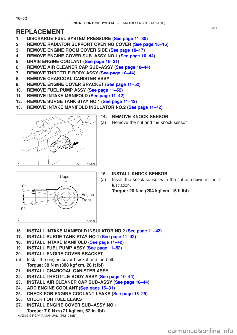
(a)Remove the nut and the knock sensor.
15.INSTALL KNOCK SENSOR
(a)Install the knock sensor with the nut as shown in the il-lustration.
Torque: 20 N �m (204 kgf �cm, 15 ft �lbf)
16.INSTALL INTAKE MANIFOLD INSULATOR NO.2 (See page 11±42)
17.INSTALL SURGE TANK STAY NO.1 (See page 11±42)
18.INSTALL INTAKE MANIFOLD (See page 11±42)
19.INSTALL FUEL PUMP ASSY (See page 11±52)
20. INSTALL ENGINE COVER BRACKET
(a) Install the engine cover bracket and the bolt. Torque: 38 N �m (388 kgf �cm, 28 ft �lbf)
21. INSTALL CHARCOAL CANISTER ASSY
22.INSTALL THROTTLE BODY ASSY (See page 10±44)
23.INSTALL AIR CLEANER CAP SUB±ASSY (See page 10±44)
24.ADD ENGINE COOLANT (See page 16±31)
25.CHECK FOR ENGINE COOLANT LEAKS (See page 16±25)
26. CHECK FOR FUEL LEAKS
27. INSTALL ENGINE COVER SUB±ASSY NO.1
Torque: 7.0 N �m (71 kgf �cm, 62 in. �lbf)
Page 1817 of 5135
100F9±01
A78507
Mass Air Flow
Meter Connector
N´m (kgf´cm, ft´lbf) : Specified torqueEngine Cover Sub±assy
No. 1
7.0 (71, 62 in.�lbf)
Air Cleaner Cap
Sub±assyVSV
Connector Fuel Vapor Feed Hose
Clip
Engine Room Cover Side
Radiator Support Opening Cover
Clip
Retainer
x2
x4
1.5 (15, 13 in.�lbf)
± ENGINE CONTROL SYSTEMKNOCK SENSOR (1AZ±FSE)
10±47
AVENSIS REPAIR MANUAL (RM1018E)
KNOCK SENSOR (1AZ±FSE)
COMPONENTS