Page 766 of 5135

05±672
±
DIAGNOSTICS ECD SYSTEM(1CD±FTV)
AVENSIS REPAIR MANUAL (RM1018E)
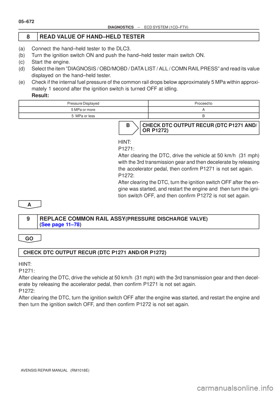
8READ VALUE OF HAND±HELD TESTER
(a)Connect the hand±held tester to the DLC3.
(b)Turn the ignition switch ON and push the hand±held tester main switch \
ON.
(c)Start the engine.
(d)Select the item ºDIAGNOSIS / OBD/MOBD / DATA LIST / ALL / COMN RAIL PRESSº and read its value displayed on the hand±held tester.
(e)Check if the internal fuel pressure of the common rail drops below approximat\
ely 5 MPa within approxi- mately 1 second after the ignition switch is turned OFF at idling.
Result:
Pressure DisplayedProceed to
5 MPa or moreA
5 MPa or lessB
BCHECK DTC OUTPUT RECUR (DTC P1271 AND/ OR P1272)
HINT:
P1271:
After clearing the DTC, drive the vehicle at 50 km/h (31 mph)
with the 3rd transmission gear and then decelerate by releasing
the accelerator pedal, then confirm P1271 is not set again.
P1272:
After clearing the DTC, turn the ignition switch OFF after the en-
gine was started, and restart the engine and then turn the igni-
tion switch OFF, and then confirm P1272 is not set again.
A
9REPLACE COMMON RAIL ASSY(PRESSURE DISCHARGE VALVE)
(See page 11±78)
GO
CHECK DTC OUTPUT RECUR (DTC P1271 AND/OR P1272)
HINT:
P1271:
After clearing the DTC, drive the vehicle at 50 km/h (31 mph) with the 3rd\
transmission gear and then decel-
erate by releasing the accelerator pedal, then confirm P1271 is not set again\
.
P1272:
After clearing the DTC, turn the ignition switch OFF after the engine was sta\
rted, and restart the engine and
then turn the ignition switch OFF, and then confirm P1272 is not set again.
Page 767 of 5135
A80997
S6
Suction Control ValveECM
E132
PCV+
2 1
LG LG±R
PCV± E131
± DIAGNOSTICSECD SYSTEM (1CD±FTV)
05±655
AVENSIS REPAIR MANUAL (RM1018E)
DTC P0627 FUEL PUMP CONTROL CIRCUIT / OPEN
CIRCUIT DESCRIPTION
DTC No.DTC Detection ConditionTrouble Area
P0627Open or short in suction control valve circuit for more than 0.5
sec. (1 trip detection logic).�Open or short in suction control valve circuit
�Suction control valve
�ECM
WIRING DIAGRAM
INSPECTION PROCEDURE
HINT:
Read freeze frame data using ��� ��������� ��
�� . Freeze frame data records the engine conditions when
a malfunction is detected. When troubleshooting, it is useful for determining whether the vehicle was running
or stopped, the engine was warmed up or not, etc. at the time of the malfunction.
05CPZ±01
Page 775 of 5135
A81010
B±Y
12
E10
2 Engine Room R/B No. 1
IE37
BATT
Battery BB
33
FL MAIN1
1A
1 Engine Room R/B No. 3
EFI
IO17
B±YECM
(LHD) (RHD)
± DIAGNOSTICSECD SYSTEM (1CD±FTV)
05±647
AVENSIS REPAIR MANUAL (RM1018E)
DTC P0560 SYSTEM VOLTAGE
CIRCUIT DESCRIPTION
While the ignition switch is OFF, the battery positive voltage is supplied to terminal BATT of the ECM for the
DTCs memory and air±fuel ratio adaptive control value memory, etc.
DTC No.DTC Detection ConditionTrouble Area
P0560Open in back±up power source circuit (1 trip detection logic).�Open in back±up power source circuit
�ECM
HINT:
If DTC P0560 appears, the ECM does not store other DTC.
WIRING DIAGRAM
INSPECTION PROCEDURE
HINT:
Read freeze frame data using ��� ��������� ��
�� . Freeze frame data records the engine conditions when
a malfunction is detected. When troubleshooting, it is useful for determining whether the vehicle was running
or stopped, the engine was warmed up or not, etc. at the time of the malfunction.
05CPX±01
Page 1186 of 5135
I35410
BB WEngine Room R/B No.3Engine Room R/B No.1,
Engine Room J/B No.1Power Heater ECU
3 3 1A 1
12 PWR HTR
P15
+
FL MAIN
Battery
ECW±B W±BJ2
J/C
AAP11
± 1
± DIAGNOSTICSCOMBUSTION TYPE POWER HEATER SYSTEM
05±1171
AVENSIS REPAIR MANUAL (RM1018E)
ECU POWER SOURCE CIRCUIT
CIRCUIT DESCRIPTION
This is power source for the power heater ECU and power heater fuel pump.
WIRING DIAGRAM
05C80±01
Page 1188 of 5135
05C7Z±01
05±1170
±
DIAGNOSTICS COMBUSTION TYPE POWER HEATER SYSTEM
AVENSIS REPAIR MANUAL (RM1018E)
PROBLEM SYMPTOMS TABLE
If the normal code is displayed during DTC check although the problem still occurs, check the circuits for
each problem symptom in the order given in the table below, and proceed to the relevant troubleshooting.
SymptomSuspect AreaSee page
The combustion type power heater does not operate
1. ECU power source circuit
2. Power heater switch circuit
3. Power heater fuel pump circuit
4. Power heater alternator circuit05±1171
05±1173
05±1176
05±1179
Page 1191 of 5135

05C7W±01
05±1166
± DIAGNOSTICSCOMBUSTION TYPE POWER HEATER SYSTEM
AVENSIS REPAIR MANUAL (RM1018E)
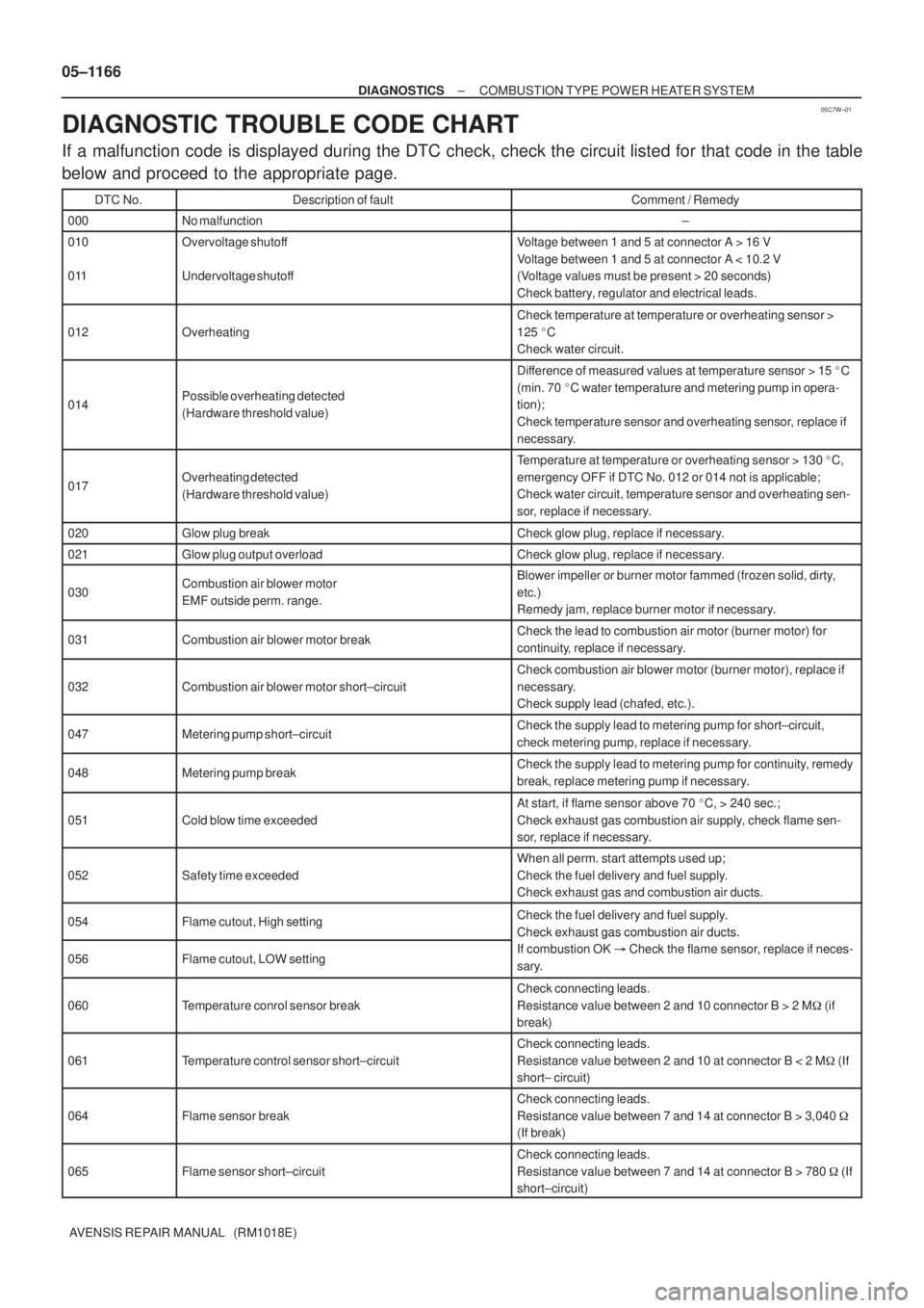
DIAGNOSTIC TROUBLE CODE CHART
If a malfunction code is displayed during the DTC check, check the circuit listed for that code in the table
below and proceed to the appropriate page.
DTC No.Description of faultComment / Remedy
000No malfunction±
010
011Overvoltage shutoff
Undervoltage shutoffVoltage between 1 and 5 at connector A > 16 V
Voltage between 1 and 5 at connector A < 10.2 V
(Voltage values must be present > 20 seconds)
Check battery, regulator and electrical leads.
012Overheating
Check temperature at temperature or overheating sensor >
125 �C
Check water circuit.
014Possible overheating detected
(Hardware threshold value)
Difference of measured values at temperature sensor > 15 �C
(min. 70 �C water temperature and metering pump in opera-
tion);
Check temperature sensor and overheating sensor, replace if
necessary.
017Overheating detected
(Hardware threshold value)
Temperature at temperature or overheating sensor > 130 �C,
emergency OFF if DTC No. 012 or 014 not is applicable;
Check water circuit, temperature sensor and overheating sen-
sor, replace if necessary.
020Glow plug breakCheck glow plug, replace if necessary.
021Glow plug output overloadCheck glow plug, replace if necessary.
030Combustion air blower motor
EMF outside perm. range.Blower impeller or burner motor fammed (frozen solid, dirty,
etc.)
Remedy jam, replace burner motor if necessary.
031Combustion air blower motor breakCheck the lead to combustion air motor (burner motor) for
continuity, replace if necessary.
032Combustion air blower motor short±circuit
Check combustion air blower motor (burner motor), replace if
necessary.
Check supply lead (chafed, etc.).
047Metering pump short±circuitCheck the supply lead to metering pump for short±circuit,
check metering pump, replace if necessary.
048Metering pump breakCheck the supply lead to metering pump for continuity, remedy
break, replace metering pump if necessary.
051Cold blow time exceeded
At start, if flame sensor above 70 �C, > 240 sec.;
Check exhaust gas combustion air supply, check flame sen-
sor, replace if necessary.
052Safety time exceeded
When all perm. start attempts used up;
Check the fuel delivery and fuel supply.
Check exhaust gas and combustion air ducts.
054Flame cutout, High settingCheck the fuel delivery and fuel supply.
Check exhaust gas combustion air ducts.
056Flame cutout, LOW setting
Check exhaust gas combustion air ducts.
If combustion OK � Check the flame sensor, replace if neces-
sary.
060Temperature conrol sensor break
Check connecting leads.
Resistance value between 2 and 10 connector B > 2 M� (if
break)
061Temperature control sensor short±circuit
Check connecting leads.
Resistance value between 2 and 10 at connector B < 2 M� (If
short± circuit)
064Flame sensor break
Check connecting leads.
Resistance value between 7 and 14 at connector B > 3,040 �
(If break)
065Flame sensor short±circuit
Check connecting leads.
Resistance value between 7 and 14 at connector B > 780 � (If
short±circuit)
Page 1244 of 5135
I35412
F17
Fuel Pump
M
21L
W±B
ECP12
F/P Power Heater ECU 05±1176
± DIAGNOSTICSCOMBUSTION TYPE POWER HEATER SYSTEM
AVENSIS REPAIR MANUAL (RM1018E)
POWER HEATER FUEL PUMP CIRCUIT
CIRCUIT DESCRIPTION
When the power heater switch is turned on, the fuel pump receives the drive voltage from the power heater
ECU, causing the combustion type power heater to operate.
WIRING DIAGRAM
05C82±01
Page 1245 of 5135
I37732
1 23 4
5 67 8
F/P
P1
I37734
12 F17
I37734
12F17
±
DIAGNOSTICS COMBUSTION TYPE POWER HEATER SYSTEM
05±1177
AVENSIS REPAIR MANUAL (RM1018E)
1CHECK WIRE HARNESS(POWER HEATER ECU ± BODY GROUND)
(a)Check for short circuit in harness and connector between
terminal F/P of power heater ECU and body ground
(See page 01±32).
NG REPAIR OR REPLACE WIRE HARNESS
OK
2 CHECK WIRE HARNESS(POWER HEATER ECU ± POWER HEATER FUEL PUMP)
(a) Check for an open or short circuit in harness and connec- tor betwen terminal 1 of power heater ECU and power
heater fuel pump (See page 01±32).
NG REPAIR OR REPLACE WIRE HARNESS
OK
3 CHECK WIRE HARNESS(POWER HEATER FUEL PUMP ± BODY GROUND)
(a) Check for an open circuit in harness and connector be- tween terminal 2 of power heater fuel pump and body
ground
(See page 01±32).
NG REPAIR OR REPLACE WIRE HARNESS
OK