Page 1246 of 5135
I36139
F17
05±1178
± DIAGNOSTICSCOMBUSTION TYPE POWER HEATER SYSTEM
AVENSIS REPAIR MANUAL (RM1018E)
4 INSPECT POWER HEATER FUEL PUMP
(a) Connect the positive (+) lead from the battery to terminal
1 and negative (±) to terminal 2 with the power heater
turned on and check the pressure of the hose by hand.
Standard: The pressure is applied to the hose.
NG REPAIR OR REPLACE POWER HEATER FUEL
PUMP
OK
PROCEED TO NEXT CIRCUIT INSPECTION SHOWN IN PROBLEM SYMPTOMS TABLE
Page 1247 of 5135
I36132
Center J/BP5
Power Heater SWPower Heater ECU
CB1
CK12
R±W G±Y G±Y
IE612
P13
SW
W±B
R±W36IG IN
2 E
Driver Side J/B
B±L
DN
DH5 1 IG1 Relay HTR
DC
DA9 6
DH1W±B
AM1
I13
Ignition SW
1 IG1 AM1 3G±R
Engine Room R/B No.3
ALT
ED11
B±L W
33
21
B
FL MAIN
Battery
IJ IKA
J15
J/C 53
12
G±Y
± DIAGNOSTICSCOMBUSTION TYPE POWER HEATER SYSTEM
05±1173
AVENSIS REPAIR MANUAL (RM1018E)
POWER HEATER SWITCH CIRCUIT
CIRCUIT DESCRIPTION
When the power heter switch is turned on, the power heater ECU sends the drive signal to the fuel pump,
causing the combustion type power heater to operate.
WIRING DIAGRAM
05C81±01
Page 1425 of 5135

05±1404
± DIAGNOSTICSAUDIO SYSTEM
AVENSIS REPAIR MANUAL (RM1018E)
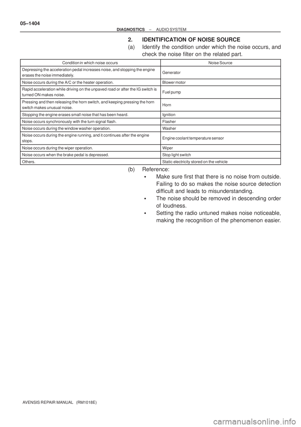
2. IDENTIFICATION OF NOISE SOURCE
(a) Identify the condition under which the noise occurs, and
check the noise filter on the related part.
Condition in which noise occursNoise Source
Depressing the acceleration pedal increases noise, and stopping the engine
erases the noise immediately.Generator
Noise occurs during the A/C or the heater operation.Blower motor
Rapid acceleration while driving on the unpaved road or after the IG switch is
turned ON makes noise.Fuel pump
Pressing and then releasing the horn switch, and keeping pressing the horn
switch makes unusual noise.Horn
Stopping the engine erases small noise that has been heard.Ignition
Noise occurs synchronously with the turn signal flash.Flasher
Noise occurs during the window washer operation.Washer
Noise occurs during the engine running, and it continues after the engine
stops.Engine coolant temperature sensor
Noise occurs during the wiper operation.Wiper
Noise occurs when the brake pedal is depressed.Stop light switch
Others.Static electricity stored on the vehicle
(b) Reference:
�Make sure first that there is no noise from outside.
Failing to do so makes the noise source detection
difficult and leads to misunderstanding.
�The noise should be removed in descending order
of loudness.
�Setting the radio untuned makes noise noticeable,
making the recognition of the phenomenon easier.
Page 1475 of 5135

± DIAGNOSTICSAUDIO SYSTEM
05±1419
AVENSIS REPAIR MANUAL (RM1018E)
NOISE OCCURS
INSPECTION PROCEDURE
1 CHECK OF SPEAKER INSTALLATION
(a) Check the speaker installation condition.
(1) Check that each speaker is securely installed.
Standard: Malfunction disappears.
HINT:
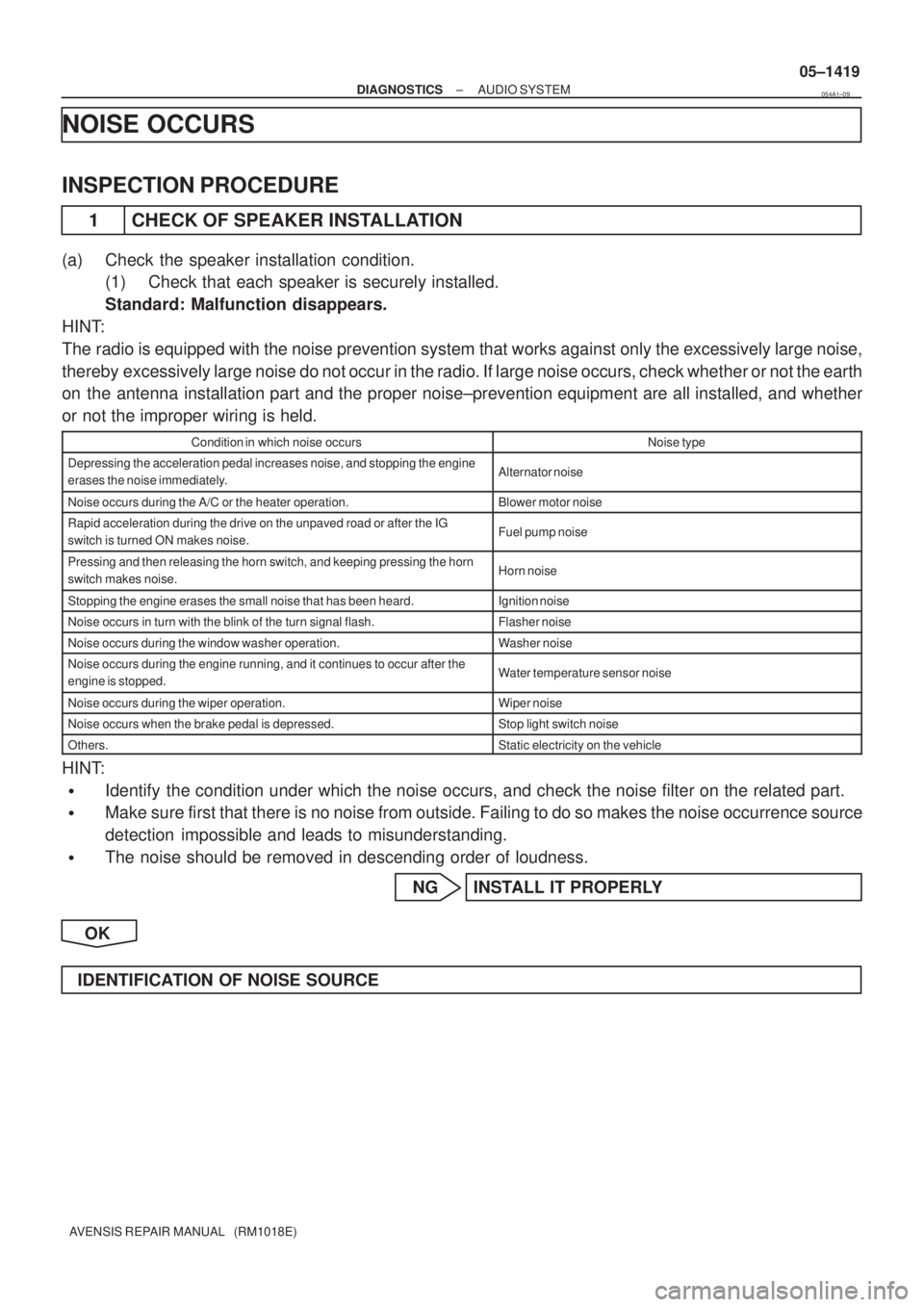
The radio is equipped with the noise prevention system that works against only the excessively large noise,
thereby excessively large noise do not occur in the radio. If large noise occurs, check whether or not the earth
on the antenna installation part and the proper noise±prevention equipment are all installed, and whether
or not the improper wiring is held.
Condition in which noise occursNoise type
Depressing the acceleration pedal increases noise, and stopping the engine
erases the noise immediately.Alternator noise
Noise occurs during the A/C or the heater operation.Blower motor noise
Rapid acceleration during the drive on the unpaved road or after the IG
switch is turned ON makes noise.Fuel pump noise
Pressing and then releasing the horn switch, and keeping pressing the horn
switch makes noise.Horn noise
Stopping the engine erases the small noise that has been heard.Ignition noise
Noise occurs in turn with the blink of the turn signal flash.Flasher noise
Noise occurs during the window washer operation.Washer noise
Noise occurs during the engine running, and it continues to occur after the
engine is stopped.Water temperature sensor noise
Noise occurs during the wiper operation.Wiper noise
Noise occurs when the brake pedal is depressed.Stop light switch noise
Others.Static electricity on the vehicle
HINT:
�Identify the condition under which the noise occurs, and check the noise filter on the related part.
�Make sure first that there is no noise from outside. Failing to do so makes the noise occurrence source
detection impossible and leads to misunderstanding.
�The noise should be removed in descending order of loudness.
NG INSTALL IT PROPERLY
OK
IDENTIFICATION OF NOISE SOURCE
054A1±09
Page 1526 of 5135
056QC±04
±
DIAGNOSTICS COMBINATION METER
05±1509
AVENSIS REPAIR MANUAL (RM1018E)
PROBLEM SYMPTOMS TABLE
Chart No.SymptomSee page
1Malfunction in speedometer05±1510
2Malfunction in tachometer05±1513
3Malfunction in water temperature receiver gauge05±1515
4Malfunction in fuel receiver gauge05±1517
5Entire combination meter does not operate05±1519
6Seat belt warning lamp for driver's seat does not operate05±1522
7Seat belt warning lamp for front passenger's seat does not flash05±1524
8The ambient temperature does not display05±1527
9Warning buzzer does not sound05±1530
Page 1528 of 5135

± DIAGNOSTICSCOMBINATION METER
05±1507
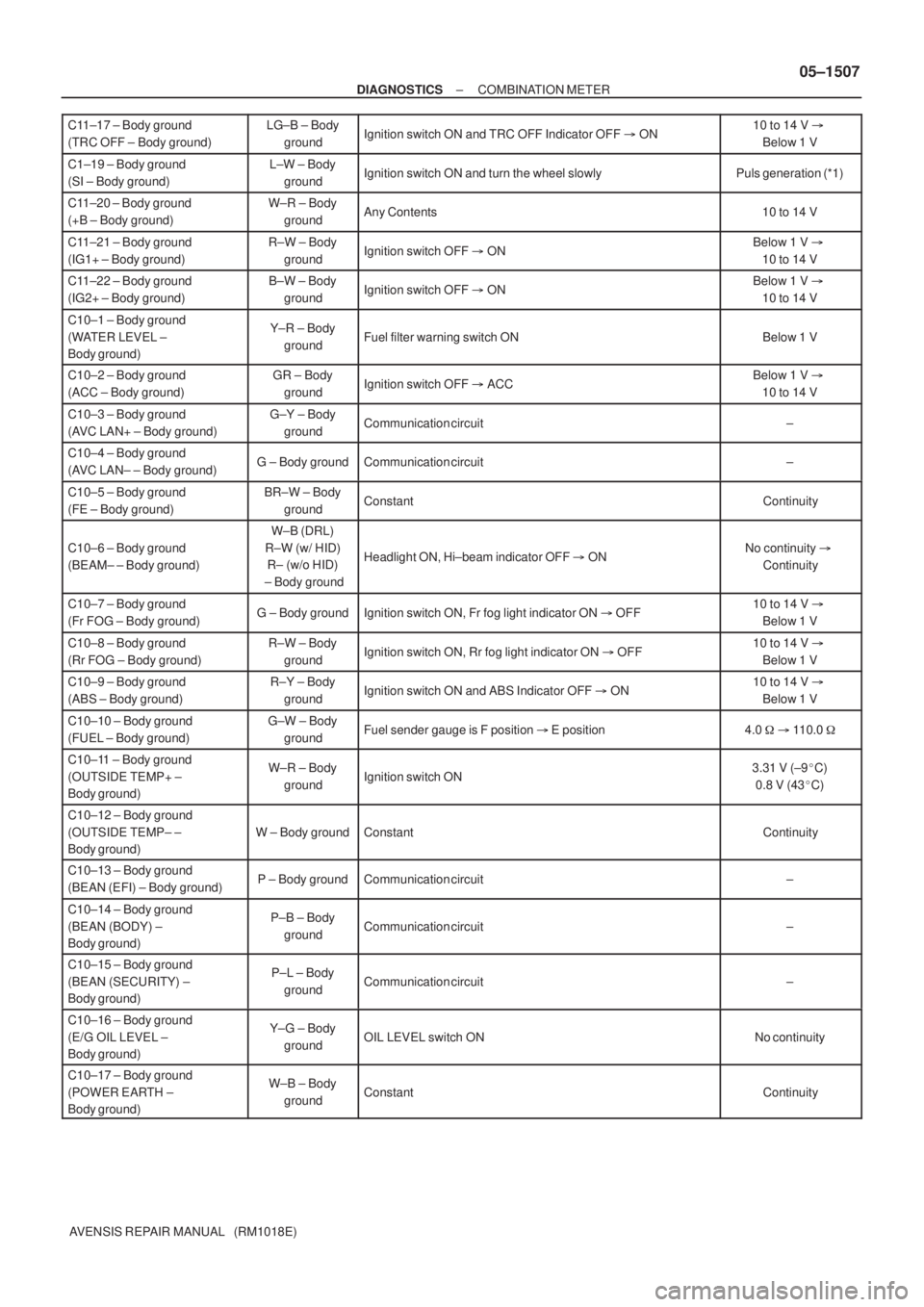
AVENSIS REPAIR MANUAL (RM1018E) C11±17 ± Body ground
(TRC OFF ± Body ground)
LG±B ± Body
groundIgnition switch ON and TRC OFF Indicator OFF � ON10 to 14 V �
Below 1 V
C1±19 ± Body ground
(SI ± Body ground)L±W ± Body
groundIgnition switch ON and turn the wheel slowlyPuls generation (*1)
C11±20 ± Body ground
(+B ± Body ground)W±R ± Body
groundAny Contents10 to 14 V
C11±21 ± Body ground
(IG1+ ± Body ground)R±W ± Body
groundIgnition switch OFF � ONBelow 1 V �
10 to 14 V
C11±22 ± Body ground
(IG2+ ± Body ground)B±W ± Body
groundIgnition switch OFF � ONBelow 1 V �
10 to 14 V
C10±1 ± Body ground
(WATER LEVEL ±
Body ground)Y±R ± Body
groundFuel filter warning switch ONBelow 1 V
C10±2 ± Body ground
(ACC ± Body ground)GR ± Body
groundIgnition switch OFF � ACCBelow 1 V �
10 to 14 V
C10±3 ± Body ground
(AVC LAN+ ± Body ground)G±Y ± Body
groundCommunication circuit±
C10±4 ± Body ground
(AVC LAN± ± Body ground)G ± Body groundCommunication circuit±
C10±5 ± Body ground
(FE ± Body ground)BR±W ± Body
groundConstantContinuity
C10±6 ± Body ground
(BEAM± ± Body ground)
W±B (DRL)
R±W (w/ HID)
R± (w/o HID)
± Body ground
Headlight ON, Hi±beam indicator OFF � ONNo continuity �
Continuity
C10±7 ± Body ground
(Fr FOG ± Body ground)G ± Body groundIgnition switch ON, Fr fog light indicator ON � OFF10 to 14 V �
Below 1 V
C10±8 ± Body ground
(Rr FOG ± Body ground)R±W ± Body
groundIgnition switch ON, Rr fog light indicator ON � OFF10 to 14 V �
Below 1 V
C10±9 ± Body ground
(ABS ± Body ground)R±Y ± Body
groundIgnition switch ON and ABS Indicator OFF � ON10 to 14 V �
Below 1 V
C10±10 ± Body ground
(FUEL ± Body ground)G±W ± Body
groundFuel sender gauge is F position � E position4.0 � � 110.0 �
C10±11 ± Body ground
(OUTSIDE TEMP+ ±
Body ground)W±R ± Body
groundIgnition switch ON3.31 V (±9�C)
0.8 V (43�C)
C10±12 ± Body ground
(OUTSIDE TEMP± ±
Body ground)
W ± Body groundConstantContinuity
C10±13 ± Body ground
(BEAN (EFI) ± Body ground)P ± Body groundCommunication circuit±
C10±14 ± Body ground
(BEAN (BODY) ±
Body ground)P±B ± Body
groundCommunication circuit±
C10±15 ± Body ground
(BEAN (SECURITY) ±
Body ground)P±L ± Body
groundCommunication circuit±
C10±16 ± Body ground
(E/G OIL LEVEL ±
Body ground)Y±G ± Body
groundOIL LEVEL switch ONNo continuity
C10±17 ± Body ground
(POWER EARTH ±
Body ground)W±B ± Body
groundConstantContinuity
Page 1530 of 5135
056QA±03
I34623
Park/Neutral Start Switch
Front Door Courtesy Switch
Front Door Courtesy Switch
Rear Door Courtesy Switch
Back Door
Courtesy Switch
Fuel Sender Gauge Assy
Engine Room No.1 J/B, R/B
Engine Room
No.4 J/B, R/B 05±1500
± DIAGNOSTICSCOMBINATION METER
AVENSIS REPAIR MANUAL (RM1018E)
LOCATION
Page 1533 of 5135
I34626
C11±14 (ILL+)
C11±1 (TURN L)
C11±13 (TURN R) C11±12 (BEAM+)
TURN±L
TURN±R TAIL IND
BEAM±
AVC±LAN
I/F
DOOR
LIGHTS
OUTSIDE TEMP
ODO/TRIP
S
T
F
W
A/T SHIFT
CLOCK
CPU POWER
SUPPLY
C11±18 (4P OUT)
C10±2 (ACC)
C11±20 (+B) C10±6 (BEAM±)
C10±3 (AVC LAN+)
C10±5 (FE) C10±4 (AVC LAN±)
C10±13 (BEAN (EFI))
C10±15 (BEAN (SECURITY))
C10±14 (BEAN (BODY)) C10±17 (POWER EARTH)
C10±12 (OUTSIDE TEMP±)
C10±11 (OUTSIDE TEMP+)
C10±10 (FUEL)
C10±16 (E/G OIL LEVEL)*1
C10±1 (WATER LEVEL)*1
C11±5 (SIGNAL EARTH)
C11±19 (SI)
C11±3 (TACHO)CPU BEAN I/F
± DIAGNOSTICSCOMBINATION METER
05±1503
AVENSIS REPAIR MANUAL (RM1018E)