Page 1884 of 5135
No.1 Fuel Pipe
Fuel Tube Connector
SST
(Clip)
SST (T joint)SST
SST
(Hose)
B12975
11±34
± FUELFUEL SYSTEM (1AZ±FSE)
AVENSIS REPAIR MANUAL (RM1018E)
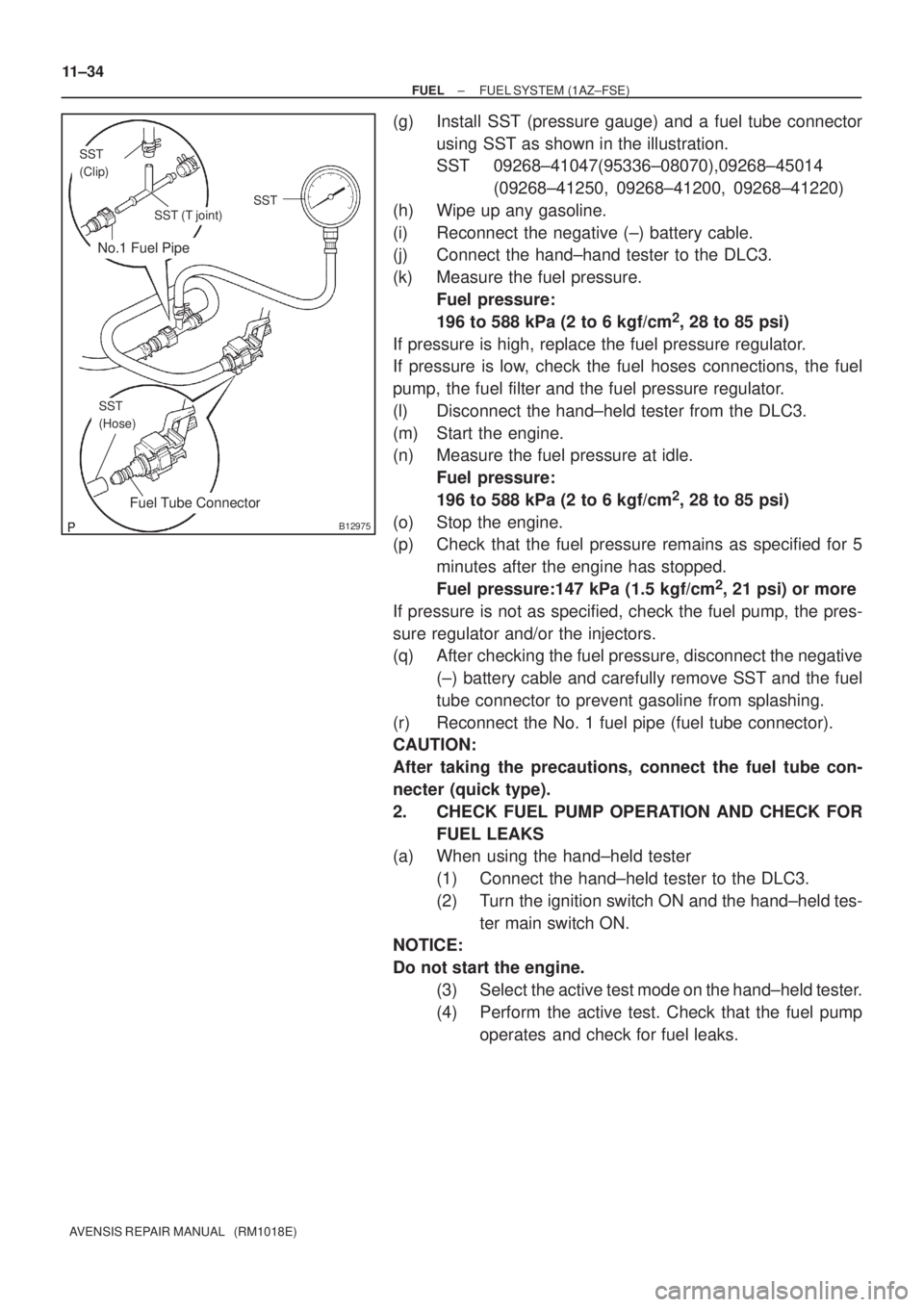
(g) Install SST (pressure gauge) and a fuel tube connector
using SST as shown in the illustration.
SST 09268±41047(95336±08070),09268±45014
(09268±41250, 09268±41200, 09268±41220)
(h) Wipe up any gasoline.
(i) Reconnect the negative (±) battery cable.
(j) Connect the hand±hand tester to the DLC3.
(k) Measure the fuel pressure.
Fuel pressure:
196 to 588 kPa (2 to 6 kgf/cm
2, 28 to 85 psi)
If pressure is high, replace the fuel pressure regulator.
If pressure is low, check the fuel hoses connections, the fuel
pump, the fuel filter and the fuel pressure regulator.
(l) Disconnect the hand±held tester from the DLC3.
(m) Start the engine.
(n) Measure the fuel pressure at idle.
Fuel pressure:
196 to 588 kPa (2 to 6 kgf/cm
2, 28 to 85 psi)
(o) Stop the engine.
(p) Check that the fuel pressure remains as specified for 5
minutes after the engine has stopped.
Fuel pressure:147 kPa (1.5 kgf/cm
2, 21 psi) or more
If pressure is not as specified, check the fuel pump, the pres-
sure regulator and/or the injectors.
(q) After checking the fuel pressure, disconnect the negative
(±) battery cable and carefully remove SST and the fuel
tube connector to prevent gasoline from splashing.
(r) Reconnect the No. 1 fuel pipe (fuel tube connector).
CAUTION:
After taking the precautions, connect the fuel tube con-
necter (quick type).
2. CHECK FUEL PUMP OPERATION AND CHECK FOR
FUEL LEAKS
(a) When using the hand±held tester
(1) Connect the hand±held tester to the DLC3.
(2) Turn the ignition switch ON and the hand±held tes-
ter main switch ON.
NOTICE:
Do not start the engine.
(3) Select the active test mode on the hand±held tester.
(4) Perform the active test. Check that the fuel pump
operates and check for fuel leaks.
Page 1885 of 5135
A75340
Battery4
5
������B12608
A76859
Hand±held Tester
± FUELFUEL SYSTEM (1AZ±FSE)
11±35
AVENSIS REPAIR MANUAL (RM1018E)
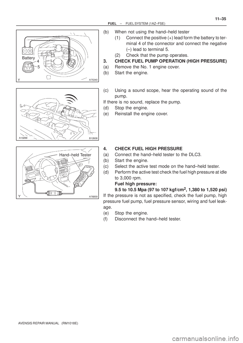
(b) When not using the hand±held tester
(1) Connect the positive (+) lead form the battery to ter-
minal 4 of the connector and connect the negative
(±) lead to terminal 5.
(2) Check that the pump operates.
3. CHECK FUEL PUMP OPERATION (HIGH PRESSURE)
(a) Remove the No. 1 engine cover.
(b) Start the engine.
(c) Using a sound scope, hear the operating sound of the
pump.
If there is no sound, replace the pump.
(d) Stop the engine.
(e) Reinstall the engine cover.
4. CHECK FUEL HIGH PRESSURE
(a) Connect the hand±held tester to the DLC3.
(b) Start the engine.
(c) Select the active test mode on the hand±held tester.
(d) Perform the active test check the fuel high pressure at idle
to 3,000 rpm.
Fuel high pressure:
9.5 to 10.5 Mpa (97 to 107 kgf/cm
2, 1,380 to 1,520 psi)
If the pressure is not as specified, check the fuel pump, high
pressure fuel pump, fuel pressure sensor, wiring and fuel leak-
age.
(e) Stop the engine.
(f) Disconnect the hand±held tester.
Page 1886 of 5135
110UZ±01
A75339
Fuel
Pump
Connector
B00679
Vinyl or Plastic Bag
11±30
±
FUEL FUEL SYSTEM(1AZ±FSE)
AVENSIS REPAIR MANUAL (RM1018E)
FUEL SYSTEM(1AZ±FSE)
PRECAUTION
1.PRECAUTION
(a)Before working on fuel system, disconnect negative (±) battery cable.
(b)Do not smoke or work near fire when handling the fuel system.
(c)Keep gasoline away from rubber or leather parts. 2.DISCHARGE FUEL SYSTEM PRESSURE
CAUTION:
�Do not disconnect any part of the fuel system until
you have discharged the fuel system pressure.
�Even after discharging the fuel pressure, place a
shop rag over fittings as you separate them to reduce
risk of fuel spray on yourself or in the engine compart-
ment.
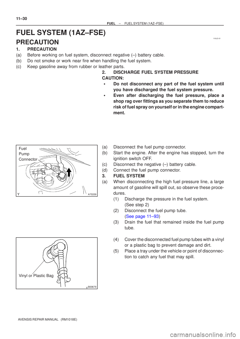
(a)Disconnect the fuel pump connector.
(b)Start the engine. After the engine has stopped, turn the ignition switch OFF.
(c)Disconnect the negative (±) battery cable.
(d)Connect the fuel pump connector.
3.FUEL SYSTEM
(a)When disconnecting the high fuel pressure line, a large amount of gasoline will spill out, so observe these proce-
dures.
(1)Discharge the pressure in the fuel system. (See step 2)
(2) Disconnect the fuel pump tube. (See page 11±93)
(3) Drain the fuel that remained inside the fuel pump
tube.
(4) Cover the disconnected fuel pump tubes with a vinyl or a plastic bag to prevent damage and dirt.
(5) Place a tray under the vehicle or point of disconnec- tion to catch any fuel that may spill.
Page 1887 of 5135
A60083
Fuel Pipe
Clamp No.1
A
A
B12941
B12944
A82344
Vinyl Bag or plastic Bag
± FUELFUEL SYSTEM (1AZ±FSE)
11±31
AVENSIS REPAIR MANUAL (RM1018E)
(b) Observe the following precautions when removing and
installing fuel injectors.
NOTICE:
Never reuse the O±ring.
(1) When installing a new O±ring to the injector, be
careful not to damage the injector.
(2) Coat the new O±ring with grease or gasoline before
installing. Never use engine oil, gear oil or brake oil.
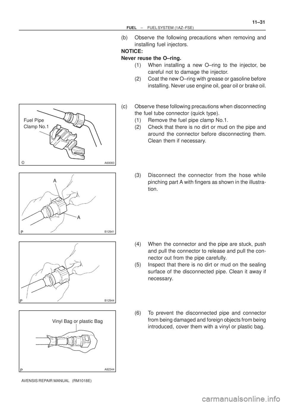
(c) Observe these following precautions when disconnecting
the fuel tube connector (quick type).
(1) Remove the fuel pipe clamp No.1.
(2) Check that there is no dirt or mud on the pipe and
around the connector before disconnecting them.
Clean them if necessary.
(3) Disconnect the connector from the hose while
pinching part A with fingers as shown in the illustra-
tion.
(4) When the connector and the pipe are stuck, push
and pull the connector to release and pull the con-
nector out from the pipe carefully.
(5) Inspect that there is no dirt or mud on the sealing
surface of the disconnected pipe. Clean it away if
necessary.
(6) To prevent the disconnected pipe and connector
from being damaged and foreign objects from being
introduced, cover them with a vinyl or plastic bag.
Page 1888 of 5135
B16534Push
B16535Pull
11±32
±
FUEL FUEL SYSTEM(1AZ±FSE)
AVENSIS REPAIR MANUAL (RM1018E)
(d)Observe these precautions when connecting the fuel tube connectors (Quick Type):
(1)Check that there is no damage or foreign objects inthe connected part of the pipe.
(2)Match the axis of the connector with the axis of the pipe, and push into the connector until the connec-
tor makes a ºclickº sound. If the connection is tight,
apply little amount of fresh engine oil on the tip of the
pipe.
(3)After having finished the connection, check if the pipe and the connector are securely connected by
pulling on them.
(4)Check for fuel leaks.
4.CHECK FOR FUEL LEAKS
(a)Check that there are no fuel leaks after doing maintenance anywhere on t\
he fuel system. (See page 11±33)
Page 1889 of 5135
110U2±01
A77915
±
FUEL FUEL PRESSURE PULSATION DAMPER
ASSY(1AZ±FE)11±29
AVENSIS REPAIR MANUAL (RM1018E)
FUEL PRESSURE PULSATION DAMPER ASSY(1AZ±FE)
REPLACEMENT
1.DISCHARGE FUEL SYSTEM PRESSURE (See page 11±15)
2.REMOVE ENGINE COVER SUB±ASSY NO.1 (See page 10±26)
3.REMOVE AIR CLEANER CAP SUB±ASSY (See page 10±26)
4.DISCONNECT FUEL TUBE SUB±ASSY (See page 11±26)
SST09268±21010
5.REMOVE FUEL PRESSURE PULSATION DAMPERASSY
(a)Remove the 2 bolts, and then remove the fuel pressure pulsation damper.
6.INSTALL FUEL PRESSURE PULSATION DAMPER ASSY
(a)Apply a light coat of spindle oil or gasoline to a new O±ring, and instal\
l it to the fuel pressure pulsation damper.
(b)Install the fuel pressure pulsation damper with the 2 bolts. Torque: 9.0 N �m (92 kgf �cm, 80 in. �lbf)
7.CONNECT FUEL TUBE SUB±ASSY (See page 11±26)
8. INSTALL AIR CLEANER CAP SUB±ASSY
9.CHECK FOR FUEL LEAKS (See page 11±19)
10.INSTALL ENGINE COVER SUB±ASSY NO.1 (See page 10±26)
Page 1890 of 5135
110U1±01
A77908
Retainer
(at 4 places)
Insert
SST
Turn
Fuel Pipe
Clamp
A76220
O±ring
Nylon Tube HousingPipe
Retainer
A77909
11±26
±
FUEL FUEL INJECTOR ASSY(1AZ±FE)
AVENSIS REPAIR MANUAL (RM1018E)
REPLACEMENT
1.DISCHARGE FUEL SYSTEM PRESSURE (See page 11±15)
2.REMOVE ENGINE COVER SUB±ASSY NO.1 (See page 10±26)
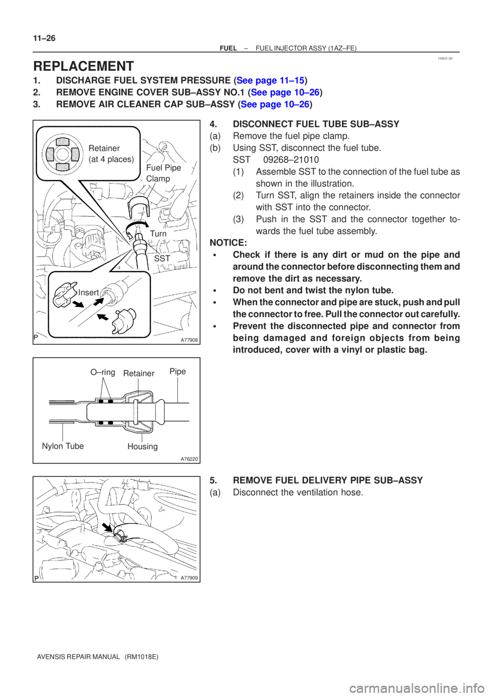
3.REMOVE AIR CLEANER CAP SUB±ASSY (See page 10±26) 4. DISCONNECT FUEL TUBE SUB±ASSY
(a) Remove the fuel pipe clamp.
(b) Using SST, disconnect the fuel tube.SST 09268±21010
(1) Assemble SST to the connection of the fuel tube asshown in the illustration.
(2) Turn SST, align the retainers inside the connector
with SST into the connector.
(3) Push in the SST and the connector together to- wards the fuel tube assembly.
NOTICE:
�Check if there is any dirt or mud on the pipe and
around the connector before disconnecting them and
remove the dirt as necessary.
�Do not bent and twist the nylon tube.
�When the connector and pipe are stuck, push and pull
the connector to free. Pull the connector out carefully.
�Prevent the disconnected pipe and connector from
being damaged and foreign objects from being
introduced, cover with a vinyl or plastic bag.
5. REMOVE FUEL DELIVERY PIPE SUB±ASSY
(a) Disconnect the ventilation hose.
Page 1891 of 5135
A77910
(b)
(b)(c)
(c)
(c)
(c)
A78437
A77911
Delivery Pipe
No. 1 Spacer
Insulator
A77912
A78481
New O±ring
± FUELFUEL INJECTOR ASSY (1AZ±FE)
11±27
AVENSIS REPAIR MANUAL (RM1018E)
(b) Remove the 2 wire harness clamps.
(c) Disconnect the 4 fuel injector connectors.
(d) Remove the 2 bolts, and then remove the fuel delivery
pipe together with the 4 fuel injectors.
NOTICE:
Be careful not to drop the fuel injectors when removing the
delivery pipe.
(e) Remove the 2 delivery pipe No. 1 spacers and the 4 insu-
lators from the cylinder head.
6. REMOVE FUEL INJECTOR ASSY
(a) Pull out the 4 fuel injectors.
7. INSTALL FUEL INJECTOR ASSY
(a) Apply a light coat of spindle oil or gasoline to new O±rings
and install them to each fuel injector.