Page 1924 of 5135

11±64
±
FUEL INJECTOR ASSY(1CD±FTV)
AVENSIS REPAIR MANUAL (RM1018E)
20.INSTALL NOZZLE HOLDER SEAL
(a)Install new 4 nozzle holder seals.
21.INSTALL TIMING BELT NO.2 C")
A79147
SST
30 cm
(11.81 in.)
11±64
±
FUEL INJECTOR ASSY(1CD±FTV)
AVENSIS REPAIR MANUAL (RM1018E)
20.INSTALL NOZZLE HOLDER SEAL
(a)Install new 4 nozzle holder seals.
21.INSTALL TIMING BELT NO.2 COVER(See page 14±307) 22. INSTALL INJECTION PIPE SUB±ASSY NO.1
NOTICE:
�In case of having the injectors replaced, must replace
the injection pipes, too.
�When assembling the pipes, perform the operation
with the engine cold under room temperature.
(a) Remove the vinyl or the plastic bag from the injector and
vinyl tape from the common rail.
(b) Temporarily install the injection pipe.
(c) Using SST, tighten the nut of the injection pipe to the com- mon rail.
SST 09023±12700
Torque:
42 N�m (428 kgf �cm, 31 ft �lbf) for a used pipe using SST
46 N �m (469 kgf �cm, 34 ft �lbf) for a used pipe not using
SST
31 N �m (316 kgf �cm, 23 ft �lbf) for a new pipe using SST
34 N �m (347 kgf �cm, 25 ft �lbf) for a new pipe not using
SST
HINT:
�Use a torque wrench with a fulcrum length of 30 cm
(11.81 in.)
�Check if the used pipe has deflection or is installed prop-
erly after injection pipe is reassembled. If there is deflec-
tion or if it can not be installed properly, replace the used
pipe with a new pipe.
(d) Using SST, tighten the nut of the injection pipe to the injec- tor.
SST 09023±12700
Torque:
42 N�m (428 kgf �cm, 31 ft �lbf) for a used pipe using SST
46 N �m (469 kgf �cm, 34 ft �lbf) for a used pipe not using
SST
31 N �m (316 kgf �cm, 23 ft �lbf) for a new pipe using SST
34 N �m (347 kgf �cm, 25 ft �lbf) for a new pipe not using
SST
HINT:
�Use a torque wrench with a fulcrum length of 30 cm
(11.81 in.)
�Check if the used pipe has deflection or is installed prop-
erly after injection pipe is reassembled. If there is deflec-
tion or if it can not be installed properly, replace the used
pipe with a new pipe.
(e) Install the 2 upper injection pipe clamps with the 2 nuts. Torque: 5.0 N �m (51 kgf �cm, 44 in. �lbf)
Page 1925 of 5135

11±65
AVENSIS REPAIR MANUAL (RM1018E)
23.INSTALL INJECTION PIPE SUB±ASSY NO.2
SST09023±12700
HINT:
Perform the same procedures as injection pipe No. 1.
24.INSTALL")
±
FUEL INJECTOR ASSY(1CD±FTV)
11±65
AVENSIS REPAIR MANUAL (RM1018E)
23.INSTALL INJECTION PIPE SUB±ASSY NO.2
SST09023±12700
HINT:
Perform the same procedures as injection pipe No. 1.
24.INSTALL INJECTION PIPE SUB±ASSY NO.3
SST09023±12700
HINT:
Perform the same procedures as injection pipe No. 1.
25.INSTALL INJECTION PIPE SUB±ASSY NO.4
SST09023±12700
HINT:
Perform the same procedures as injection pipe No. 1.
26.INSTALL AIR TUBE NO.1 (See page 14±270)
27. INSTALL AIR CLEANER ASSY Torque: 7.0 N �m (71 kgf �cm, 62 in. �lbf)
28. INSTALL ENGINE COVER NO.1
Torque: 8.0 N �m (82 kgf �cm, 71 in. �lbf)
29. INSTALL VACUUM RESERVOIR SUB±ASSY Torque: 8.3 N �m (85 kgf �cm, 74 in. �lbf)
30. CHECK FOR FUEL LEAKS
NOTICE:
Under ACTIVE TEST mode, fuel pressure increases. Take precautions to prevent fuel from spraying
on you or inside the engine compartment.
HINT:
During ACTIVE TEST mode, engine speed goes high and combustion noise bec\
omes loud.
(a) Check that there are no fuel leaks from any part of the fuel system at t\
he engine stops.
HINT:
If fuel leakage could be found on specific parts, replace them with new \
parts.
(b) While cranking or when starting the engine, check that there is no leaks from\
any part of the fuel sys-
tem.
HINT:
If fuel leakage could be found on specific parts, replace them with new pa\
rts.
(c) Disconnect the fuel hose from the common rail.
(d) While cranking the engine, check fuel leaks from the return pipe.
HINT:
If there is fuel leakage, replace the common rail.
(e) Connect the hand±held tester to the DLC3.
(f) Start the engine and push the hand±held tester main switch ON.
(g) Select the FUEL LEAK test of ACTIVE TEST mode on the hand±held tester\
.
(h) If you do not have the hand±held tester, depress the accelerator pedal quickly and fully to increase the engine speed at maximum and keep it for 2 seconds. Repeat this opera\
tion several times.
(i) Check that there are no leaks from any part of the fuel system.
NOTICE:
If the leakage from the return pipe is less than 10 cc (0.6 cu in.) in\
a minute, it is acceptable.
HINT:
If fuel leakage could be found on specific parts, replace them with new \
parts.
(j) Reconnect the fuel hose to the common rail.
Page 1926 of 5135
110U7±01
A79434
Radiator Support Opening Cover
Engine Cover No. 1
Vacuum Reservoir Sub±assy
Union To Connector Tube Hose
Air Cleaner Cap w/ Hose
Air Cleaner Element
Air Cleaner Case
N´m (kgf´cm, ft´lbf)
: Specified torque
8.0 (82, 71 in.�lbf)
8.3 (85, 73 in.�lbf)
7.0 (71, 62 in.�lbf)
Clip
Retainer
25 (255, 18)
Air Tube No. 1
25 (255, 18)
11±58
± FUELINJECTOR ASSY (1CD±FTV)
AVENSIS REPAIR MANUAL (RM1018E)
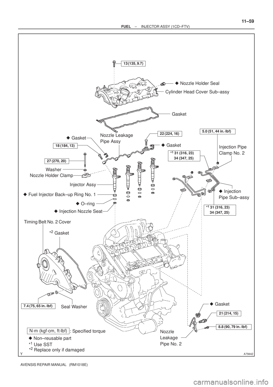
INJECTOR ASSY (1CD±FTV)
COMPONENTS
Page 1927 of 5135
A79442
Timing Belt No. 2 Cover
Seal Washer *
2 Gasket
Injection Pipe
Clamp No. 2
� Injection
Pipe Sub±assy
13 (135, 9.7)
Cylinder Head Cover Sub±assy
Gasket
� Nozzle Holder Seal
� Gasket
� O±ring � Fuel Injector Back±up Ring No. 1
� Injection Nozzle Seat Washer
Nozzle Holder ClampNozzle Leakage
Pipe Assy
Injector Assy
N´m (kgf´cm, ft´lbf)
: Specified torque
� Non±reusable part
7.4 (75, 65 in.´lbf)
*1 31 (316, 23)
34 (347, 25)
� Gasket
22 (224, 16)
18 (184, 13)
27 (270, 20)
Nozzle
Leakage
Pipe No. 2
*1 Use SST
*2 Replace only if damaged
*1 31 (316, 23)
34 (347, 25)
5.0 (51, 44 in.´lbf)
� Gasket
21 (214, 15)
8.8 (90, 79 in.´lbf)
± FUELINJECTOR ASSY (1CD±FTV)
11±59
AVENSIS REPAIR MANUAL (RM1018E)
Page 1928 of 5135

AVENSIS REPAIR MANUAL (RM1018E)
FUEL SY")
110CX±02
A75346
A79038
E2S PR2 VCS
VCPR E2
Fuel pressure sensor
A79039Pressure discharge valve
A62162
Vacuum Switch Body
11±56
± FUELFUEL SYSTEM (1CD±FTV)
AVENSIS REPAIR MANUAL (RM1018E)
FUEL SYSTEM (1CD±FTV)
INSPECTION
1. INJECTION OR SUPPLY PUMP ASSY
(a) Resistance inspection.
(1) Using an ohmmeter, measure the resistance be-
tween the terminals.
Resistance: 1.5 to 2.3 � at 20�C (68�F)
2. INJECTOR ASSY
(a) Resistance inspection.
(1) Using an ohmmeter, measure the resistance between the terminals.
Resistance: 0.85 to 1.05 � at 20�C (68�F)
3. COMMON RAIL ASSY
(a) Resistance inspection. (Fuel pressure sensor)
(1) Using an ohmmeter, measure the resistance be-
tween terminals 5 (PR) and 4 (E2).
Resistance: 16.4 k�or less
(2) Using an ohmmeter, measure the resistance be-
tween terminals 2 (PR2) and 3 (E2S).
Resistance: 16.4 k�or less
(3) Using an ohmmeter, measure the resistance be-
tween terminals 6 (VC) and 5 (PR).
Resistance: 3 k�or less
(4) Using an ohmmeter, measure the resistance be-
tween terminals 1 (VCS) and 2 (PR2).
Resistance: 3 k�or less
(b) Resistance inspection. (Pressure discharge valve)
(1) Using an ohmmeter, measure the resistance be-
tween terminals.
Resistance: 0.85 to 1.05 � at 20�C (68�F)
4. FUEL HEATER ASSY
(a) Resistance inspection.
(1) Apply a vacuum of 34.7 � 5.3 kPa (260 � 40
mmHg, 10.24 � 1.57 in Hg) to the vacuum switch
port.
(2) Using an ohmmeter, measure the resistance be-
tween terminal 2 and switch body.
Resistance: 0.5 to 20 � at 20�C (68�F)
Page 1929 of 5135
± FUELFUEL SYSTEM (1CD±FTV)
11±57
AVENSIS REPAIR MANUAL (RM1018E)
5. LEVEL WARNING SWITCH
(a) Continuity inspection.
(1) Using an ohmmeter, check that there is continuity between terminals.
Specified condition:
There is continuity when raising a float.
There is no continuity when letting a float down.
6. FUEL TEMPERATURE SENSOR
(a) Resistance inspection.
(1) Using an ohmmeter, measure the resistance between the terminals.
Resistance:
Approx. 20�C (68�F) 2.21 to 2.69 �
Approx. 80�C (176�F) 0.287 to 0.349 �
Page 1930 of 5135

AVENSIS REPAIR MANUAL (RM1018E)
REPLACEMENT
1.DISCHARGE FUEL SYSTEM PRESSURE (See page 11±30)
2.REMOVE RADIATOR SUP")
110TB±01
A79569
A79570
SST
A79571
A79572
11±52
±
FUEL FUEL PUMP ASSY(1AZ±FSE)
AVENSIS REPAIR MANUAL (RM1018E)
REPLACEMENT
1.DISCHARGE FUEL SYSTEM PRESSURE (See page 11±30)
2.REMOVE RADIATOR SUPPORT OPENING COVER (See page 18±16)
3.REMOVE ENGINE COVER SUB±ASSY NO.1 (See page 10±44)
4.REMOVE AIR CLEANER CAP SUB±ASSY (See page 10±44) 5.REMOVE ENGINE COVER BRACKET
(a)Remove the bolt and the engine cover bracket.
6.REMOVE FUEL PRESSURE PULSATION DAMPERASSY
(a)Disconnect the fuel tube sub±assy. (See page 11±30)
(b) Using SST, remove the fuel pressure pulsation damper assy, the fuel tube sub±assy and the 2 gasket.
SST 09617±24011
7. REMOVE FUEL PIPE SUB±ASSY NO.1
(a) Remove the fuel hose.
(b) Clamp the union bolt on the fuel pump assy with a 21 mm wrench and remove the fuel pipe sub±assy No. 1 from the
fuel pump assy using a 19 mm union±nut wrench.
NOTICE:
Do not loosen the union bolt on the fuel pump assy. If it be-
come loose, replace the fuel pump assy with new fuel
pump assy.
Page 1931 of 5135

11±53
AVENSIS REPAIR MANUAL (RM1018E)
(c) Remove the 2 bolts first, then remove the fuel pipe sub±
assy No. 1 from the fuel delivery pipe sub�")
A79573
A79574
A79834
± FUELFUEL PUMP ASSY (1AZ±FSE)
11±53
AVENSIS REPAIR MANUAL (RM1018E)
(c) Remove the 2 bolts first, then remove the fuel pipe sub±
assy No. 1 from the fuel delivery pipe sub±assy.
NOTICE:
Be careful not to damage both the sealing surfaces of the
fuel delivery pipe and the fuel pump when removing the
fuel pipe No.1.
8. REMOVE FUEL PUMP ASSY
(a) Disconnect the fuel pump assy connector.
(b) Remove the 2 nuts and the fuel pump assy.
(c) Remove the fuel pump insulator.
9. INSTALL FUEL PUMP ASSY
(a) Turn the crankshaft and set the camshaft to the position
where the oil port of the camshaft can be seen from the
fuel pump mounting hole.
(b) From the fuel pump mounting hole of the cylinder head,
pour 35 to 45cc (2.14 to 2.75 cu in) engine oil into the cyl-
inder head.
(c) For more smooth rotation, apply engine oil on the cam
lobe which can be seen from the fuel pump mounting hole
using fingers.
(d) Set a new fuel pump insulator and fuel pump assy with the
2 nuts.
Torque: 25 N�m (255 kgf�cm, 18 ft�lbf)


11±57
AVENSIS REPAIR MANUAL (RM1018E)
5. LEVEL WARNING SWITCH
(a) Continuity inspection.
(1) Using an ohmmeter, check that there is continuity between terminals.
Speci")