Page 1997 of 5135

AVENSIS REPAIR MANUAL (RM1018E)
(b)Install a new gasket and the manifold converter, and tem- porarily tighten bolt")
������������A80106
A
A
B
B
A79163
13±16
±
INTAKE TURBOCHARGER SUB±ASSY(1CD±FTV)
AVENSIS REPAIR MANUAL (RM1018E)
(b)Install a new gasket and the manifold converter, and tem- porarily tighten bolts A and bolts B while pushing the up-
per portion of the converter toward the turbocharger.
Torque: 8.0 N �m (82 kgf �cm, 71 in. �lbf)
(c)Tighten the 3 nuts. Torque: 25 N �m (255 kgf �cm, 18 ft �lbf)
(d)Tighten bolts A.
Torque: 61 N �m (622 kgf �cm, 45 ft �lbf)
(e)Tighten bolts B. Torque: 61 N �m (622 kgf �cm, 45 ft �lbf)
31.INSTALL MANIFOLD STAY NO.2
(a)Install the manifold stay No. 2, and temporarily tighten the bolt.
(b)Temporarily tighten the nut while pushing the manifold stay No. 2 toward the cylinder head.
Torque: 8.0 N �m (82 kgf �cm, 71 in. �lbf)
HINT:
No clearance between the stay and the cylinder head should be
confirmed.
(c)Tighten the bolt. Torque: 56 N �m (571 kgf �cm, 41 ft �lbf)
(d)Tighten the nut. Torque: 56 N �m (571 kgf �cm, 41 ft �lbf)
32.INSTALL EXHAUST MANIFOLD HEAT INSULATOR NO.2
Torque: 12 N �m (122 kgf �cm, 8.9 ft �lbf)
33.INSTALL TURBO INSULATOR NO.1 Torque: 20 N �m (204 kgf �cm, 15 ft �lbf)
34.INSTALL TURBO INSULATOR NO.2
Torque: 20 N �m (204 kgf �cm, 15 ft �lbf)
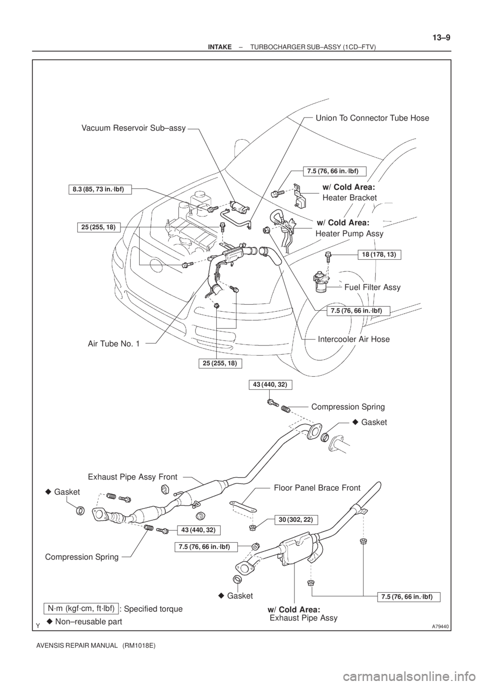
35.INSTALL EXHAUST PIPE ASSY (W/ COLD AREA) Torque: 7.5 N �m (76 kgf �cm, 66 in. �lbf)
36.INSTALL EXHAUST PIPE ASSY FRONT(See page 15±10)
37.INSTALL FLOOR PANEL BRACE FRONT(See page 15±10)
38. INSTALL HEATER BRACKET (W/ COLD AREA) Torque: 7.5 N �m (76 kgf �cm, 66 in. �lbf)
39. INSTALL HEATER PUMP ASSY (W/ COLD AREA) Torque: 7.5 N �m (76 kgf �cm, 66 in. �lbf)
40.INSTALL FUEL FILTER ASSY(See page 11±82)
Page 1998 of 5135
A64328
2 to 7 mm0 to 2 mm
A78274
Upward90�
Clamp
Bolt
±
INTAKE TURBOCHARGER SUB±ASSY(1CD±FTV)
13±17
AVENSIS REPAIR MANUAL (RM1018E)
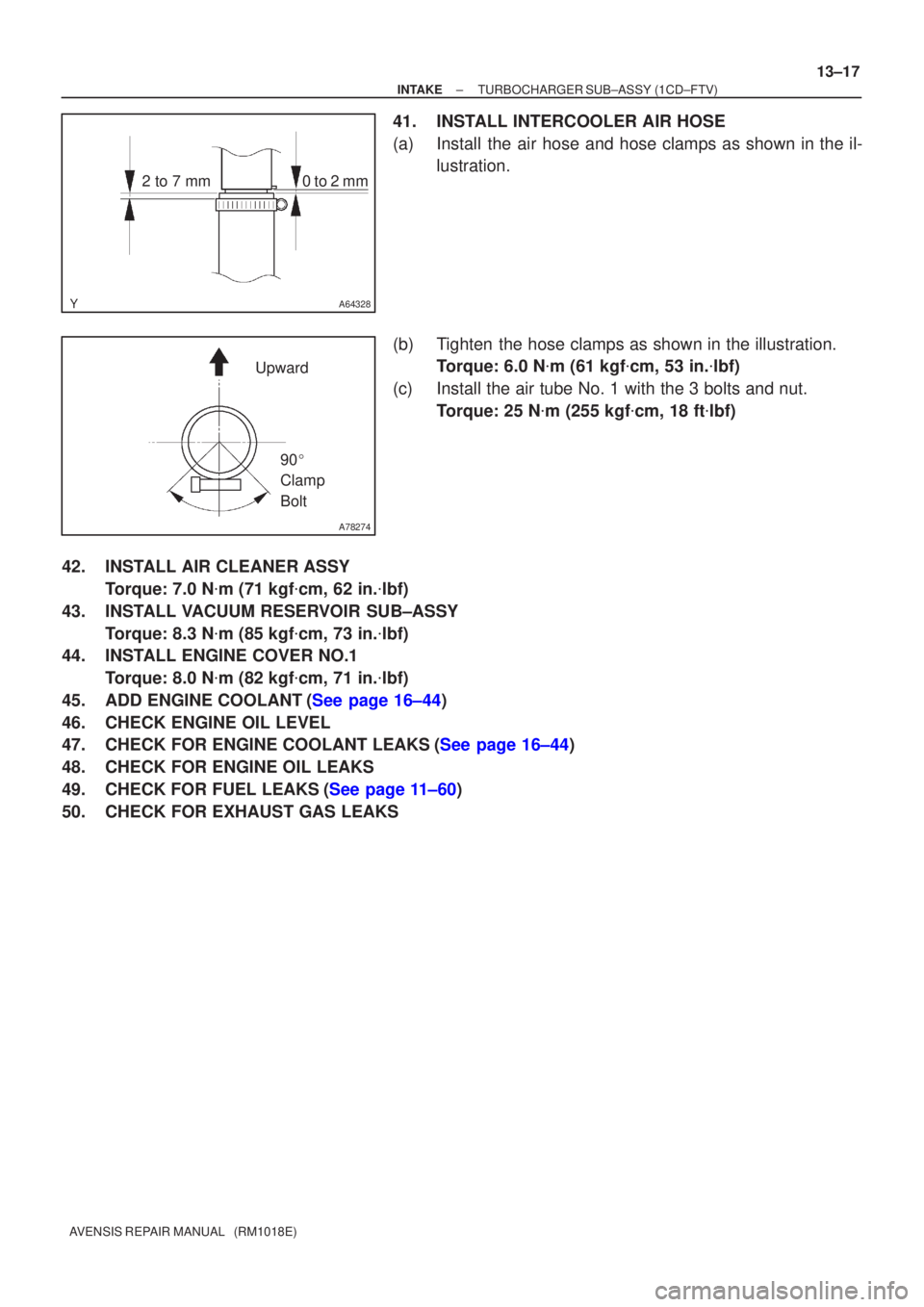
41.INSTALL INTERCOOLER AIR HOSE
(a)Install the air hose and hose clamps as shown in the il-
lustration.
(b)Tighten the hose clamps as shown in the illustration. Torque: 6.0 N �m (61 kgf �cm, 53 in. �lbf)
(c)Install the air tube No. 1 with the 3 bolts and nut. Torque: 25 N �m (255 kgf �cm, 18 ft �lbf)
42.INSTALL AIR CLEANER ASSY Torque: 7.0 N �m (71 kgf �cm, 62 in. �lbf)
43.INSTALL VACUUM RESERVOIR SUB±ASSY Torque: 8.3 N �m (85 kgf �cm, 73 in. �lbf)
44.INSTALL ENGINE COVER NO.1
Torque: 8.0 N �m (82 kgf �cm, 71 in. �lbf)
45.ADD ENGINE COOLANT(See page 16±44)
46. CHECK ENGINE OIL LEVEL
47.CHECK FOR ENGINE COOLANT LEAKS(See page 16±44)
48. CHECK FOR ENGINE OIL LEAKS
49.CHECK FOR FUEL LEAKS(See page 11±60)
50. CHECK FOR EXHAUST GAS LEAKS
Page 2000 of 5135
A79440
Union To Connector Tube Hose
Fuel Filter Assy Vacuum Reservoir Sub±assy
43 (440, 32)
43 (440, 32)
� Gasket
� GasketCompression Spring
Floor Panel Brace Front Exhaust Pipe Assy Front
Compression Spring
N´m (kgf´cm, ft´lbf)
: Specified torque
� Non±reusable part
Intercooler Air Hose
� Gasket
7.5 (76, 66 in.�lbf)
Exhaust Pipe Assy
30 (302, 22)
7.5 (76, 66 in.�lbf)
Heater Bracket
Heater Pump Assy25 (255, 18)
25 (255, 18)
7.5 (76, 66 in.�lbf)
18 (178, 13)
7.5 (76, 66 in.�lbf)
w/ Cold Area:
w/ Cold Area:
w/ Cold Area:
8.3 (85, 73 in.�lbf)
Air Tube No. 1
± INTAKETURBOCHARGER SUB±ASSY (1CD±FTV)
13±9
AVENSIS REPAIR MANUAL (RM1018E)
Page 2005 of 5135

13±3
AVENSIS REPAIR MANUAL (RM1018E)
TURBO CHARGER SYSTEM (1CD±FTV)
PRECAUTION
1. MAINTENANCE PRECAUTION
(a) Do not stop the")
1302Y±03
A77119
A77120
A77121
± INTAKETURBO CHARGER SYSTEM (1CD±FTV)
13±3
AVENSIS REPAIR MANUAL (RM1018E)
TURBO CHARGER SYSTEM (1CD±FTV)
PRECAUTION
1. MAINTENANCE PRECAUTION
(a) Do not stop the engine immediately after pulling a trailer,
or after driving at a high speed, or uphill drive. Let the en-
gine Idle for 20 to 120 seconds before turn the ignition
switch OFF (According as the driving condition, the idling
time varies).
(b) Avoid quick acceleration or quickly accelerating the en-
gine RPM immediately after the starting a cold engine.
(c) If the turbocharger is found to be defective, it must be re-
placed. Also, inspect a source of the trouble including
conditions of the turbocharger that having been used. Re-
pair or replace the followings as necessary:
(1) Engine oil (Level and quality)
(2) Oil lines leading to the turbocharger
(d) Pay due attention when removing and reinstalling the
turbocharger assembly. Do not drop, or do not give shock,
or do not grasp easily±deformed assembly parts such as
the actuator or push rod in removal and reinstallation.
(e) Before removal, cover both the intake and exhaust ports
and the oil inlet to prevent dirt or foreign objects from be-
ing introduced.
(f) If replacing the turbocharger, check for deposits in the oil
pipe. If necessary, replace the oil pipe too.
(g) Thoroughly remove old gasket sticking to the lubrication
oil pipe flange and the turbocharger oil flange.
(h) If replacing the bolt(s) or nut(s), must use Toyota genuine
parts to prevent breakage or deformation.
(i) If replacing the turbocharger, put 20 cm
3 (1.2 cu in.) of
fresh oil into the turbocharger oil inlet hole and turn the tur-
bine wheel by hand to spread oil to the bearing.
(j) If overhauling or replacing the engine, cut the fuel supply
after reassembly and crank the engine for 30 seconds to
feed oil throughout the engine then run the engine at idle
for 60 seconds.
Page 2043 of 5135
141CG±01
A784575 Claws
A78458
A78505
A78515
±
ENGINE MECHANICAL PARTIAL ENGINE ASSY (1ZZ±FE/3ZZ±FE)
14±27
AVENSIS REPAIR MANUAL (RM1018E)
REPLACEMENT
1.DISCHARGE FUEL SYSTEM PRESSURE (See page 11±1)
2. REMOVE RADIATOR SUPPORT OPENING COVER
(a) Remove the retainer and the 4 clips.
(b) Unfasten the 5 claws, and remove the radiator supportopening cover.
3. REMOVE ENGINE ROOM COVER SIDE
(a) Remove the 2 clips and the engine room cover side.
4. REMOVE FRONT WHEELS
5. REMOVE ENGINE UNDER COVER SUB±ASSY NO.1
(a) Remove the 5 clips, 2 screws, bolt and detach the engine under cover.
6. REMOVE ENGINE UNDER COVER LH
(a) Remove the 6 screws and 5 clips, then detach the engine under cover.
Page 2045 of 5135

14±29
AVENSIS REPAIR MANUAL (RM1018E)
20. REMOVE RADIATOR ASSY
(a) Remove the 2 bolts and the")
A76724
A76714
A78461
1ZZ±FE
A78497
3ZZ±FE
±
ENGINE MECHANICAL PARTIAL ENGINE ASSY (1ZZ±FE/3ZZ±FE)
14±29
AVENSIS REPAIR MANUAL (RM1018E)
20. REMOVE RADIATOR ASSY
(a) Remove the 2 bolts and the relay block.
(b) Disconnect the connector and the 2 harness clamps.
(c) Remove the 2 bolts, the 2 radiator support upper and the
radiator.
21. REMOVE BATTERY
22. REMOVE BATTERY TRAY
23. REMOVE BATTERY CARRIER
(a) Remove the 4 bolts, the battery carrier and the bracket.
24.REMOVE EFI FUEL PIPE CLAMP(See page 11±11)
25. DISCONNECT FUEL TUBE SUB±ASSY (See page 11±11)
26. SEPARATE ACCELERATOR CONTROL CABLE ASSY
(a) Loosen the nut and separate the accelerator control cable.
27. DISCONNECT UNION TO CONNECTOR TUBE HOSE
(a) Disconnect the union to connector tube hose.
28. DISCONNECT HEATER INLET WATER HOSE
(a) Disconnect the heater inlet water hose from the heater core inlet tube.
29. DISCONNECT HEATER OUTLET WATER HOSE
(a) Disconnect the heater outlet water hose from the heater core outlet tube\
.
30. DISCONNECT OIL COOLER INLET HOSE (A/T TRANSAXLE)
(a) Disconnect the oil cooler inlet hose from the automatic transaxle.
31. DISCONNECT OIL COOLER OUTLET HOSE (A/T TRANSAXLE)
(a) Disconnect the oil cooler outlet hose from the automatic transaxle.
Page 2050 of 5135
A76713
A64023
A79363
A64026
14±34
±
ENGINE MECHANICAL PARTIAL ENGINE ASSY (1ZZ±FE/3ZZ±FE)
AVENSIS REPAIR MANUAL (RM1018E)
(b) Remove the 2 nuts which are used to secure the engine wire.
(c) Remove the 4 bolts and the 4 ignition coils.
69. REMOVE FUEL DELIVERY PIPE SUB±ASSY (See page 11±11)
70. REMOVE INTAKE MANIFOLD
(a) Disconnect the 2 water hoses from the throttle body.
(b) Disconnect the ventilation hose and the ventilation hose No. 2 from the cylinder head cover.
(c) Disconnect the vacuum hose from the water by±pass
pipe No. 1.
(d) Remove the 4 bolts, 2 nuts and 2 wire brackets,then re- move the intake manifold and the throttle body assembly.
(e) Remove the gasket from the intake manifold and the
throttle body assembly.
71. REMOVE OIL LEVEL GAGE SUB±ASSY
(a) Remove the oil level gage from the oil level gage guide.
72. REMOVE OIL LEVEL GAGE GUIDE
(a) Disconnect the crank shaft position sensor cramp.
(b) Remove the bolt and the oil level gage guide.
Page 2056 of 5135

AVENSIS REPAIR MANUAL (RM1018E)
107. INSTALL WATER INLET
(a) Install the water inlet with the 2 n")
A64028
A64027
A64026
A79363
A64023
14±40
±
ENGINE MECHANICAL PARTIAL ENGINE ASSY (1ZZ±FE/3ZZ±FE)
AVENSIS REPAIR MANUAL (RM1018E)
107. INSTALL WATER INLET
(a) Install the water inlet with the 2 nuts. Torque: 11 N �m (112 kgf �cm, 8 ft �lbf)
108. INSTALL WATER BY±PASS PIPE NO.1
(a) Install a new gasket and water by±pass pipe with the 2 nuts and 2 bolts.
Torque: 9.0 N �m (92 kgf �cm, 80 in. �lbf)
109. INSTALL OIL LEVEL GAGE GUIDE
(a) Apply a light coat of engine oil a new O±ring and install it to the oil level gage guide.
(b) Install the oil level gage guide with the bolt. Torque: 13 N �m (133 kgf �cm, 10 ft �lbf)
110. INSTALL INTAKE MANIFOLD
(a) Install a new gasket to the intake manifold.
(b) Install the intake manifold and 2 clamp brackets with the 2 nuts and 4 bolts.
Torque: 30 N �m (306 kgf �cm, 22 ft �lbf)
111. INSTALL FUEL DELIVERY PIPE SUB±ASSY (See page 11±11)
112. INSTALL IGNITION COIL ASSY
(a) Install the 4 ignition coils with the 4 bolts. Torque: 9.0 N �m (92 kgf �cm, 80 in. �lbf)

14±27
AVENSIS REPAIR MANUAL (RM1018E)
REPLACEMENT
1.DISCHARGE FUEL SYSTEM PRESSURE (See page")

AVENSIS REPAIR MANUAL (RM1018E)
(b) Remove the 2 nuts which are used to secure the engine wire.
(c) Remo")