Page 1786 of 5135
100FG±01
A77870
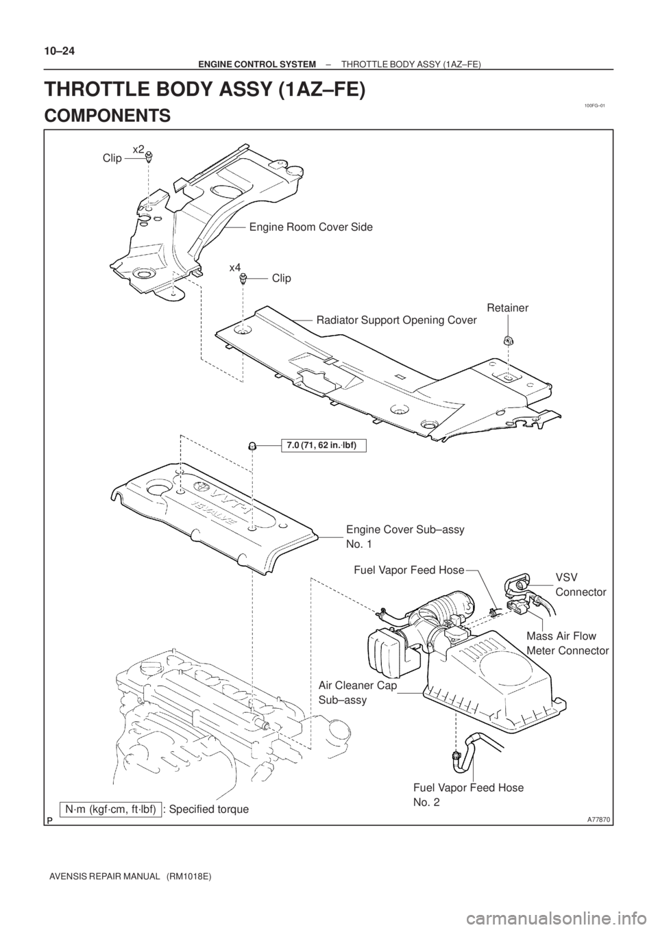
Mass Air Flow
Meter Connector
N´m (kgf´cm, ft´lbf) : Specified torqueEngine Cover Sub±assy
No. 1
7.0 (71, 62 in.�lbf)
Fuel Vapor Feed Hose
No. 2
Air Cleaner Cap
Sub±assyVSV
Connector Fuel Vapor Feed Hose
Clip
Engine Room Cover Side
Radiator Support Opening Cover
Clip
Retainer
x2
x4 10±24
± ENGINE CONTROL SYSTEMTHROTTLE BODY ASSY (1AZ±FE)
AVENSIS REPAIR MANUAL (RM1018E)
THROTTLE BODY ASSY (1AZ±FE)
COMPONENTS
Page 1795 of 5135

(b)
(c)
A78499
(d)
(e)
A78500
±
ENGINE CONTROL SYSTEM THROTTLE BODY ASSY(3ZZ±FE)
10±15
AVENSIS REPAIR MANUAL (RM1018E)
Removal & Installation and Disassembly & Reassem")
100FE±01
A78497
A78498
(a)
(b)
(c)
A78499
(d)
(e)
A78500
±
ENGINE CONTROL SYSTEM THROTTLE BODY ASSY(3ZZ±FE)
10±15
AVENSIS REPAIR MANUAL (RM1018E)
Removal & Installation and Disassembly & Reassembly
1.REMOVE RADIATOR SUPPORT OPENING COVER (See page 10±9)
2.REMOVE ENGINE ROOM COVER SIDE (See page 10±9)
3.DRAIN ENGINE COOLANT (See page 16±7)
4.REMOVE CYLINDER HEAD COVER NO.2 (See page 10±9)
5.REMOVE AIR CLEANER CAP SUB±ASSY (See page 10±9)
6. SEPARATE ACCELERATOR CONTROL CABLE ASSY
(a) Loosen the nut and separate the accelerator controlcable.
7. REMOVE THROTTLE BODY ASSY
(a) Disconnect the ventilation hose.
(b) Disconnect the water by±pass hose.
(c) Disconnect the water by±pass hose No. 2.
(d) Disconnect the throttle position sensor.
(e) Disconnect the ISC valve connector.
(f) Remove the bolt and 2 nuts, and then remove the acceler- ator control bracket and the throttle body.
(g) Remove the gasket from the intake manifold.
8. REMOVE ISC VALVE
(a) Remove the 4 screws, and then remove the ISC valve.
(b) Remove the gasket from the throttle body.
Page 1796 of 5135

Rotation
Center of
Throttle Link
11�
10±16
±
ENGINE CONTROL SYSTEM THROTTLE BODY ASSY(3ZZ±FE)
AVENSIS REPAIR MANUAL (RM1018E)
9.REMOVE THRO")
A78501
A78503
30� to 45 �
A78469
66.3 mm
(2.610 in.)
Rotation
Center of
Throttle Link
11�
10±16
±
ENGINE CONTROL SYSTEM THROTTLE BODY ASSY(3ZZ±FE)
AVENSIS REPAIR MANUAL (RM1018E)
9.REMOVE THROTTLE POSITION SENSOR
(a)Remove the 2 screws, and then remove the throttle posi- tion sensor.
10.INSTALL THROTTLE POSITION SENSOR
(a)Make sure that the throttle valve is fully closed.
(b)With the throttle position sensor rotated 30 � to 45 � coun-
terclockwise about the fully closed position of the throttle
valve, install the throttle position sensor to the throttle
body.
(c)Rotate the throttle position sensor clockwise and secure it with the 2 screws.
Torque: 2.0 N �m (20 kgf �cm, 18 in. �lbf)
11.INSTALL ISC VALVE
(a)Install a new gasket to the throttle body.
(b)Install the ISC valve with the 4 screws.
Torque: 3.7 N �m (38 kgf �cm, 33 in. �lbf)
12.INSTALL THROTTLE BODY ASSY
(a)Install a new gasket to the intake manifold.
(b)Install the throttle body and the accelerator control brack- et with the bolt and 2 nuts.
Torque: 30 N �m (306 kgf �cm, 22 ft �lbf)
13.INSTALL ACCELERATOR CONTROL CABLE ASSY
(a)Install the accelerator control cable as shown in the il- lustration.
Torque: 13 N �m (129 kgf �cm, 9 ft �lbf)
14.INSTALL AIR CLEANER CAP SUB±ASSY (See page 10±9)
15.INSTALL CYLINDER HEAD COVER NO.2 (See page 10±9)
16.ADD ENGINE COOLANT (See page 16±7)
17.CHECK FOR ENGINE COOLANT LEAKS (See page 16±1)
18. INSTALL ENGINE ROOM COVER SIDE
19. INSTALL RADIATOR SUPPORT OPENING COVER
Page 1797 of 5135
100FD±01
A78454
N´m (kgf´cm, ft´lbf) : Specified torqueClip
Cylinder Head Cover No.2
Fuel
Vapor Feed Hose No.1
VSV
Connector
Mass Air Flow
Meter Connector Accelerator Control
Cable Assy
Fuel Vapor Feed Hose
No.3 Engine Room Cover Side
Radiator Support Opening Cover
Clip
Retainer
7.0 (71, 62 in.´lbf)
Clip
1.5 (15, 13 in.´lbf)
13 (129, 9)
Air Cleaner Cap
Sub±assy
x2
x4
± ENGINE CONTROL SYSTEMTHROTTLE BODY ASSY (3ZZ±FE)
10±13
AVENSIS REPAIR MANUAL (RM1018E)
THROTTLE BODY ASSY (3ZZ±FE)
COMPONENTS
Page 1799 of 5135
100FC±01
A784575 Claws
A78458
A78459
±
ENGINE CONTROL SYSTEM THROTTLE BODY ASSY(1ZZ±FE)
10±9
AVENSIS REPAIR MANUAL (RM1018E)
Removal & Installation and Disassembly & Reassembly
1.REMOVE RADIATOR SUPPORT OPENING COVER
(a)Remove the retainer and 4 clips.
(b)Unfasten the 5 claws and remove the radiator support
opening cover.
2.REMOVE ENGINE ROOM COVER SIDE
(a)Remove the 2 clips, and then remove the engine room cover side.
3.DRAIN ENGINE COOLANT (See page 16±7)
4. REMOVE CYLINDER HEAD COVER NO.2
(a) Remove the 2 nuts and 2 clips, and then remove the cylin- der head cover No. 2.
Page 1802 of 5135

(c)
A78468
65.1 mm
(2.563 in.)
Rotation
Center of
Throttle Link
18�
10±12
±
ENGINE CONTROL SYSTEM THROTTLE BODY ASSY(1ZZ±FE)
AVENSIS REPAIR MANUAL (RM1018E)
14.INSTALL")
A78463
A
A
A
A
BB
A
(d)
(c)
A78468
65.1 mm
(2.563 in.)
Rotation
Center of
Throttle Link
18�
10±12
±
ENGINE CONTROL SYSTEM THROTTLE BODY ASSY(1ZZ±FE)
AVENSIS REPAIR MANUAL (RM1018E)
14.INSTALL THROTTLE BODY ASSY
(a)Install a new gasket to the intake manifold.
(b)Install the throttle body and the throttle body bracket with the 3 bolts and 2 nuts. (A/T)
Torque:
30 N�m (306 kgf �cm, 22 ft �lbf) for bolt and nut A
(c)Install the throttle body and the throttle body bracket with
the 5 bolts and 2 nuts. (M/T)
Torque:
30 N�m (306 kgf �cm, 22 ft �lbf) for bolt and nut A
13 N �m (133 kgf �cm, 10 ft �lbf) for bolt B
(d)Connect the ISC valve connector.
(e)Connect the throttle position sensor connector.
(f)Connect the ventilation hose.
(g)Connect the water by±pass hose No. 2.
(h)Connect the water by±pass hose.
15.INSTALL ACCELERATOR CONTROL CABLE ASSY
(a)Install the accelerator control cable as shown in the il-
lustration.
Torque: 13 N �m (129 kgf �cm, 9 ft �lbf)
16.INSTALL AIR CLEANER CAP SUB±ASSY Torque: 1.5 N �m (15 kgf �cm, 13 in. �lbf)
17.INSTALL CYLINDER HEAD COVER NO.2 Torque: 7.0 N �m (71 kgf �cm, 62 in. �lbf)
18.ADD ENGINE COOLANT (See page 16±7)
19.CHECK FOR ENGINE COOLANT LEAKS (See page 16±1)
20. INSTALL ENGINE ROOM COVER SIDE
21. INSTALL RADIATOR SUPPORT OPENING COVER
Page 1803 of 5135
100FB±01
A78454
N´m (kgf´cm, ft´lbf) : Specified torqueClip
Cylinder Head Cover No.2
Fuel
Vapor Feed Hose No.1
VSV
Connector
Mass Air Flow
Meter Connector Accelerator Control
Cable Assy
Fuel Vapor Feed Hose
No.3 Engine Room Cover Side
Radiator Support Opening Cover
Clip
Retainer
7.0 (71, 62 in.´lbf)
Clip
1.5 (15, 13 in.´lbf)
13 (129, 9)
Air Cleaner Cap
Sub±assy
x2
x4
± ENGINE CONTROL SYSTEMTHROTTLE BODY ASSY (1ZZ±FE)
10±7
AVENSIS REPAIR MANUAL (RM1018E)
THROTTLE BODY ASSY (1ZZ±FE)
COMPONENTS
Page 1815 of 5135

AVENSIS REPAIR MANUAL (RM1018E)
REPLACEMENT
1.DISCHARGE FUEL SYSTEM PRESSURE (See page 11�")
100FA±01
A79596
A78436
10�
10 � Upper
Engine
Front
10±52
±
ENGINE CONTROL SYSTEM KNOCK SENSOR(1AZ±FSE)
AVENSIS REPAIR MANUAL (RM1018E)
REPLACEMENT
1.DISCHARGE FUEL SYSTEM PRESSURE (See page 11±30)
2.REMOVE RADIATOR SUPPORT OPENING COVER (See page 18±16)
3.REMOVE ENGINE ROOM COVER SIDE (See page 18±17)
4.REMOVE ENGINE COVER SUB±ASSY NO.1 (See page 10±44)
5.DRAIN ENGINE COOLANT (See page 16±31)
6.REMOVE AIR CLEANER CAP SUB±ASSY (See page 10±44)
7.REMOVE THROTTLE BODY ASSY (See page 10±44)
8.REMOVE CHARCOAL CANISTER ASSY
9.REMOVE ENGINE COVER BRACKET (See page 11±52)
10.REMOVE FUEL PUMP ASSY (See page 11±52)
11.REMOVE INTAKE MANIFOLD (See page 11±42)
12.REMOVE SURGE TANK STAY NO.1 (See page 11±42)
13.REMOVE INTAKE MANIFOLD INSULATOR NO.2 (See page 11±42) 14.REMOVE KNOCK SENSOR
(a)Remove the nut and the knock sensor.
15.INSTALL KNOCK SENSOR
(a)Install the knock sensor with the nut as shown in the il-lustration.
Torque: 20 N �m (204 kgf �cm, 15 ft �lbf)
16.INSTALL INTAKE MANIFOLD INSULATOR NO.2 (See page 11±42)
17.INSTALL SURGE TANK STAY NO.1 (See page 11±42)
18.INSTALL INTAKE MANIFOLD (See page 11±42)
19.INSTALL FUEL PUMP ASSY (See page 11±52)
20. INSTALL ENGINE COVER BRACKET
(a) Install the engine cover bracket and the bolt. Torque: 38 N �m (388 kgf �cm, 28 ft �lbf)
21. INSTALL CHARCOAL CANISTER ASSY
22.INSTALL THROTTLE BODY ASSY (See page 10±44)
23.INSTALL AIR CLEANER CAP SUB±ASSY (See page 10±44)
24.ADD ENGINE COOLANT (See page 16±31)
25.CHECK FOR ENGINE COOLANT LEAKS (See page 16±25)
26. CHECK FOR FUEL LEAKS
27. INSTALL ENGINE COVER SUB±ASSY NO.1
Torque: 7.0 N �m (71 kgf �cm, 62 in. �lbf)
 : Specified torqueClip
Cylinder Head Cover No.2
Fuel
Vapor Feed Hose No.1
VSV
Connector
Mass Air Flow
Meter Connector Accelerator Control
Cable Assy
Fuel V")

10±9
AVENSIS REPAIR MANUAL (RM1018E)
Removal & Installation and Disassembly & Reassembly
1.REMOVE RADIATOR")
 : Specified torqueClip
Cylinder Head Cover No.2
Fuel
Vapor Feed Hose No.1
VSV
Connector
Mass Air Flow
Meter Connector Accelerator Control
Cable Assy
Fuel V")