Page 1972 of 5135
141CE±01
A78459
A76713
A64023
A65078
14±6
±
ENGINE MECHANICAL VALVE CLEARANCE(1ZZ±FE/3ZZ±FE)
AVENSIS REPAIR MANUAL (RM1018E)
VALVE CLEARANCE(1ZZ±FE/3ZZ±FE)
ADJUSTMENT
1.REMOVE RADIATOR SUPPORT OPENING COVER(See page 14±27)
2.REMOVE ENGINE ROOM COVER SIDE(See page 14±27) 3. REMOVE CYLINDER HEAD COVER NO.2
(a) Remove the 2 nuts and 2 clips and detach cylinder headcover No.2.
4. DISCONNECT IGNITION COIL ASSY
(a) Remove the 5 clamps from the 5 clamp brackets.
(b) Disconnect the 4 ignition coil connectors.
(c) Remove the 2 nuts which are used to secure the engine wire.
(d) Remove the 4 bolts and the 4 ignition coils.
5. DISCONNECT VENTILATION HOSE
(a) Disconnect the ventilation hose from the cylinder head cover.
Page 1985 of 5135
141CD±01
A60622
±
ENGINE MECHANICAL FAN AND GENERATOR V BELT(1ZZ±FE/3ZZ±FE)
14±5
AVENSIS REPAIR MANUAL (RM1018E)
FAN AND GENERATOR V BELT(1ZZ±FE/3ZZ±FE)
REPLACEMENT
1.REMOVE RADIATOR SUPPORT OPENING COVER (See page 14±27)
2.REMOVE ENGINE ROOM COVER SIDE (See page 14±27)
3.REMOVE ENGINE UNDER COVER SUB±ASSY NO.1 (See page 14±27)
4. REMOVE FAN AND GENERATOR V BELT
(a) Turn the V±ribbed belt tensioner clockwise slowly andloosen it. Then, remove the fan and generator V belt and
put back the V±ribbed belt tensioner carefully.
Page 1992 of 5135
1306Z±01
A79155
A80093
A79158
±
INTAKE TURBOCHARGER SUB±ASSY(1CD±FTV)
13±11
AVENSIS REPAIR MANUAL (RM1018E)
REPLACEMENT
1.REMOVE ENGINE UNDER COVER SUB±ASSY NO.1
2.DRAIN ENGINE COOLANT(See page 16±44)
3.REMOVE RADIATOR SUPPORT OPENING COVER
4.REMOVE ENGINE COVER NO.1
(a)Remove the 5 nuts and the engine cover.
5.REMOVE VACUUM RESERVOIR SUB±ASSY
(a)Disconnect the 2 vacuum hoses and the connector.
(b)Remove the 2 bolts and the vacuum reservoir.
6.REMOVE AIR CLEANER ASSY
(a)Disconnect the PCV hose and the connector.
(b)Remove the air cleaner cap with the air cleaner hose.
(c)Remove the air cleaner filter element.
(d)Remove the 3 bolts and the air cleaner case. 7.REMOVE INTERCOOLER AIR HOSE
(a)Remove the 3 bolts and nut, separate the air tube No.1.
(b)Loosen the hose clamp bolts and remove the air hoseNo.1.
8.REMOVE FUEL FILTER ASSY(See page 11±82) 9. SEPARATE HEATER PUMP ASSY (W/ COLD AREA)
(a) Remove the nut and disconnect the connector.
(b) Separate the heater pump.
Page 1999 of 5135
1306Y±01
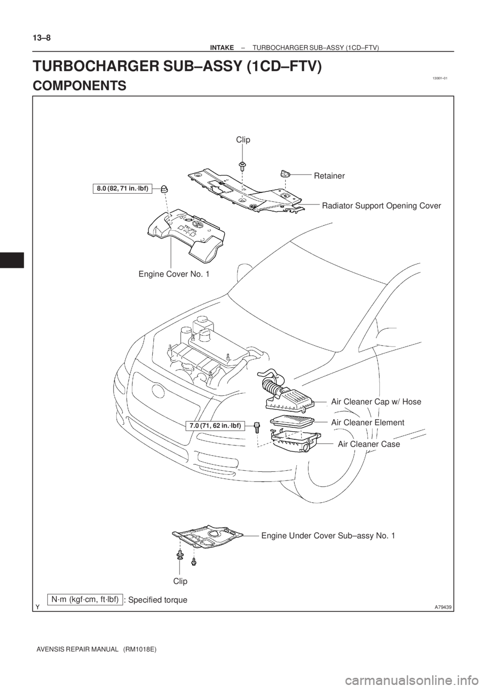
A79439
8.0 (82, 71 in.�lbf)
Engine Cover No. 1Radiator Support Opening Cover
N´m (kgf´cm, ft´lbf)
: Specified torque
7.0 (71, 62 in.�lbf)
Air Cleaner Cap w/ Hose
Air Cleaner Element
Air Cleaner Case
Engine Under Cover Sub±assy No. 1
Clip
Retainer
Clip
13±8
± INTAKETURBOCHARGER SUB±ASSY (1CD±FTV)
AVENSIS REPAIR MANUAL (RM1018E)
TURBOCHARGER SUB±ASSY (1CD±FTV)
COMPONENTS
Page 2012 of 5135
141CK±01
A78459
A76713
A64023
A65078
14±64
±
ENGINE MECHANICAL CAMSHAFT(1ZZ±FE/3ZZ±FE)
AVENSIS REPAIR MANUAL (RM1018E)
REPLACEMENT
1.REMOVE RADIATOR SUPPORT OPENING COVER (See page 14±27)
2.REMOVE ENGINE UNDER COVER RH (See page 14±27) 3. REMOVE CYLINDER HEAD COVER NO.2
(a) Remove and the 2 screw and 2 clips and detach the en-gine under cover No.2.
4. DISCONNECT COIL, IGNITION
(a) Remove the 5 clamps from the 5 clamp brackets.
(b) Disconnect the 4 ignition coil connectors.
(c) Remove the 2 nuts which are used to secure the engine wire.
(d) Remove the 4 bolts and the 4 ignition coils.
5. DISCONNECT VENTILATION HOSE
(a) Disconnect the ventilation hose from the cylinder head cover.
Page 2024 of 5135
141CJ±01
A79321
Clip
Engine Room Side Cover RH
Retainer Clip
Radiator Cover Assy
Clip
Engine Under Cover RH
Engine Under Cover No. 1
Clip
14±60
± ENGINE MECHANICALCAMSHAFT (1ZZ±FE/3ZZ±FE)
AVENSIS REPAIR MANUAL (RM1018E)
CAMSHAFT (1ZZ±FE/3ZZ±FE)
COMPONENTS
Page 2028 of 5135

14±49
AVENSIS REPAIR MANUAL (RM1018E)
REPLACEMENT
1.REMOVE RADIATOR SUPPORT OPENING COVER (See page 14±2")
141CI±01
A78459
A60622
A79324
A76713
±
ENGINE MECHANICAL CHAIN SUB±ASSY(1ZZ±FE/3ZZ±FE)
14±49
AVENSIS REPAIR MANUAL (RM1018E)
REPLACEMENT
1.REMOVE RADIATOR SUPPORT OPENING COVER (See page 14±27)
2.REMOVE ENGINE ROOM COVER SIDE (See page 14±27)
3.REMOVE FRONT WHEEL RH
4.REMOVE ENGINE UNDER COVER SUB±ASSY NO.1 (See page 14±27)
5.REMOVE ENGINE UNDER COVER RH (See page 14±27)
6.DRAIN ENGINE COOLANT (See page 16±7)
7.REMOVE CYLINDER HEAD COVER NO.2
(a)Remove the 2 nuts and 2 clips and detach the cylinderhead cover No.2.
8.REMOVE FAN AND GENERATOR V BELT
(a)Turn the V±ribbed belt tensioner clockwise slowly and loosen it. Then, remove the fan and generator V belt and
put back the V±ribbed belt tensioner carefully.
9.REMOVE V±RIBBED IDLER ASSY NO.1
(a)Remove the nut, bolt, tube and idler.
10.REMOVE GENERATOR ASSY (See page 19±7)
11. REMOVE IGNITION COIL ASSY
(a) Remove the 5 clamps from the 5 clamp brackets.
(b) Disconnect the 4 ignition coil connectors.
(c) Remove the 2 nuts which are used to secure the engine wire.
Page 2039 of 5135
141CH±01
A79321
Clip
Engine Room Side Cover RH
Retainer Clip
Radiator Cover Assy
Clip
Engine Under Cover RH
Engine Under Cover No. 1
Clip
± ENGINE MECHANICALCHAIN SUB±ASSY (1ZZ±FE/3ZZ±FE)
14±45
AVENSIS REPAIR MANUAL (RM1018E)
CHAIN SUB±ASSY (1ZZ±FE/3ZZ±FE)
COMPONENTS

AVENSIS REPAIR MANUAL (RM1018E)
VALVE CLEARANCE(1ZZ±FE/3ZZ±FE)
ADJUSTMENT
1.REMOVE RADIATOR SUPPOR")

14±5
AVENSIS REPAIR MANUAL (RM1018E)
FAN AND GENERATOR V BELT(1ZZ±FE/3ZZ±FE)
REPLACEMENT
1.REMOVE RADIATOR SUPPORT")

13±11
AVENSIS REPAIR MANUAL (RM1018E)
REPLACEMENT
1.REMOVE ENGINE UNDER COVER SUB±ASSY NO.1
2.DRAIN ENGINE COOLANT(See pag")

AVENSIS REPAIR MANUAL (RM1018E)
REPLACEMENT
1.REMOVE RADIATOR SUPPORT OPENING COVER (See page 14±27)
2.RE")

AVENSIS")

14±45")