Page 2106 of 5135

141CN±01
A60622
A01045
A64005
A62837SST
14±96±
ENGINE MECHANICAL TIMING CHAIN OR BELT COVER OIL
SEAL(1ZZ±FE/3ZZ±FE)
AVENSIS REPAIR MANUAL (RM1018E)
TIMING GEAR COVER OIL SEAL(1ZZ±FE/3ZZ±FE)
REPLACEMENT
1.REMOVE FRONT WHEEL RH (See page 14±27)
2.REMOVE ENGINE UNDER COVER SUB±ASSY NO.1 (See page 14±27)
3.REMOVE ENGINE UNDER COVER RH (See page 14±27)
4.REMOVE RADIATOR SUPPORT OPENING COVER (See page 14±27)
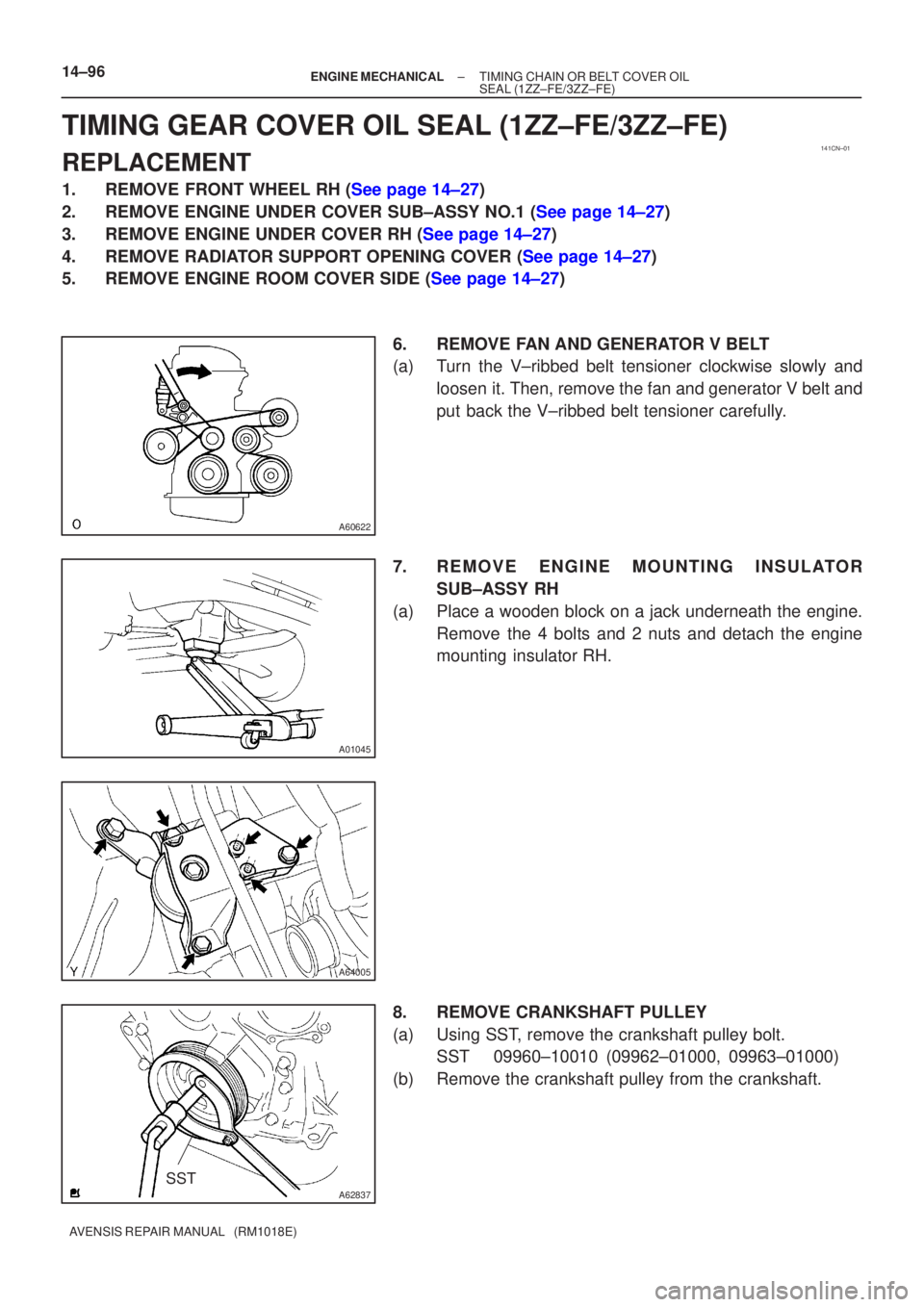
5.REMOVE ENGINE ROOM COVER SIDE (See page 14±27) 6. REMOVE FAN AND GENERATOR V BELT
(a) Turn the V±ribbed belt tensioner clockwise slowly andloosen it. Then, remove the fan and generator V belt and
put back the V±ribbed belt tensioner carefully.
7. REMOVE ENGINE MOUNTING INSULATOR SUB±ASSY RH
(a) Place a wooden block on a jack underneath the engine. Remove the 4 bolts and 2 nuts and detach the engine
mounting insulator RH.
8. REMOVE CRANKSHAFT PULLEY
(a) Using SST, remove the crankshaft pulley bolt. SST 09960±10010 (09962±01000, 09963±01000)
(b) Remove the crankshaft pulley from the crankshaft.
Page 2108 of 5135

141CM±01
A78459
A78461
1ZZ±FE
A78497
3ZZ±FE
±
ENGINE MECHANICAL CYLINDER HEAD GASKET(1ZZ±FE/3ZZ±FE)
14±81
AVENSIS REPAIR MANUAL (RM1018E)
REPLACEMENT
1.DISCHARGE FUEL SYSTEM PRESSURE(See page 11±1)
2.REMOVE RADIATOR SUPPORT OPENING COVER (See page 14±27)
3.REMOVE ENGINE ROOM COVER SIDE (See page 14±27)
4.REMOVE FRONT WHEEL RH
5.REMOVE ENGINE UNDER COVER SUB±ASSY NO.1 (See page 14±27)
6.REMOVE ENGINE UNDER COVER RH (See page 14±27)
7.DRAIN ENGINE COOLANT(See page 16±7)
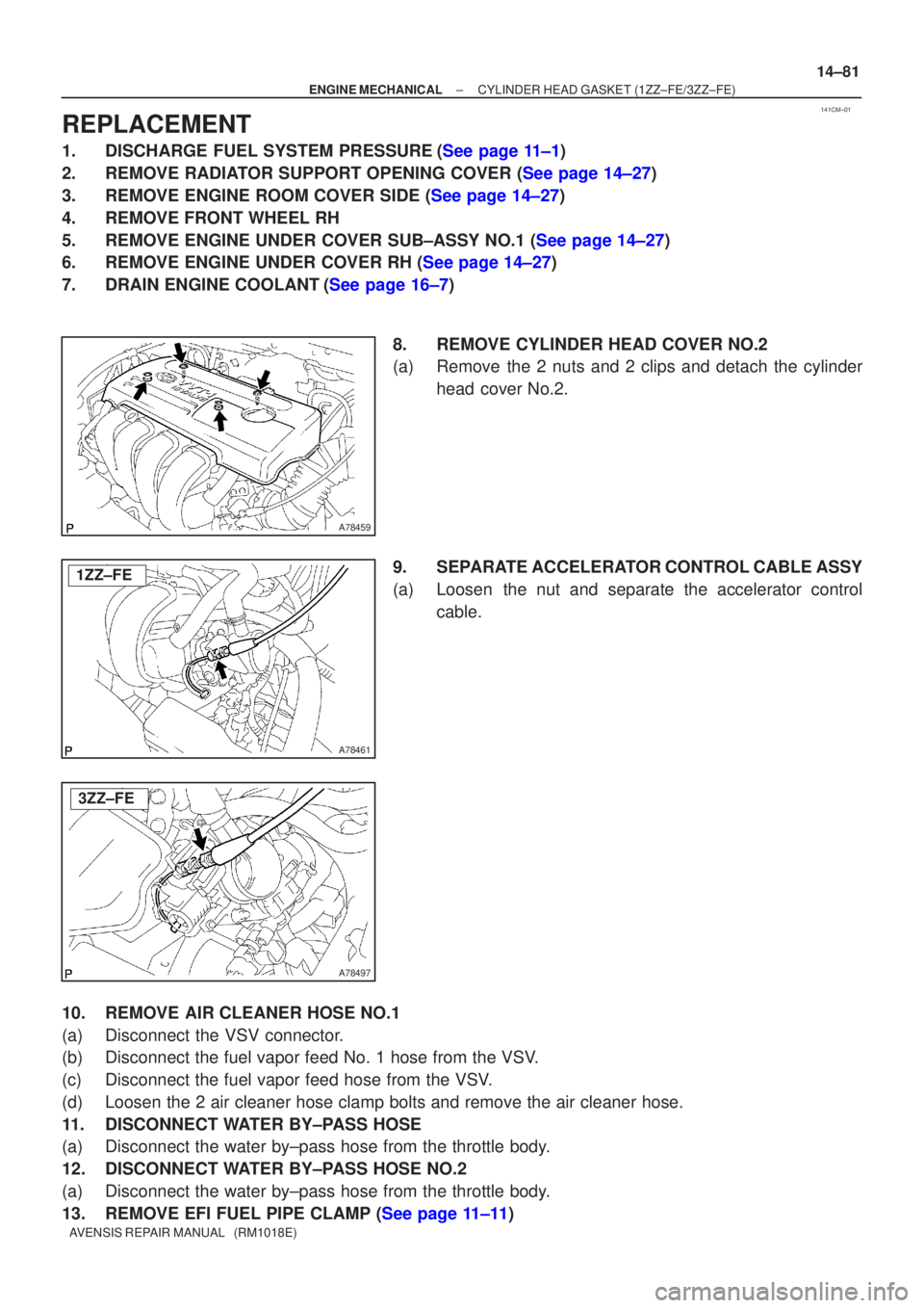
8.REMOVE CYLINDER HEAD COVER NO.2
(a)Remove the 2 nuts and 2 clips and detach the cylinderhead cover No.2.
9.SEPARATE ACCELERATOR CONTROL CABLE ASSY
(a)Loosen the nut and separate the accelerator control cable.
10.REMOVE AIR CLEANER HOSE NO.1
(a)Disconnect the VSV connector.
(b)Disconnect the fuel vapor feed No. 1 hose from the VSV.
(c)Disconnect the fuel vapor feed hose from the VSV.
(d)Loosen the 2 air cleaner hose clamp bolts and remove the air cleaner hos\
e.
11.DISCONNECT WATER BY±PASS HOSE
(a)Disconnect the water by±pass hose from the throttle body.
12.DISCONNECT WATER BY±PASS HOSE NO.2
(a)Disconnect the water by±pass hose from the throttle body.
13.REMOVE EFI FUEL PIPE CLAMP (See page 11±11)
Page 2109 of 5135

A60622
A79324
A76713
A64023
14±82
±
ENGINE MECHANICAL CYLINDER HEAD GASKET(1ZZ±FE/3ZZ±FE)
AVENSIS REPAIR MANUAL (RM1018E)
14.DISCONNECT FUEL TUBE SUB±ASSY (See page 11±11) SST09268±21010
15.DISCONNECT UNION TO CONNECTOR TUBE HOSE
(a)Disconnect the union to connector tube hose from the hose to hose tube.
16.DISCONNECT RADIATOR HOSE INLET
(a)Disconnect radiator hose inlet from the cylinder head.
17.DISCONNECT HEATER INLET WATER HOSE
(a)Disconnect the heater inlet water hose from the cylinder head.
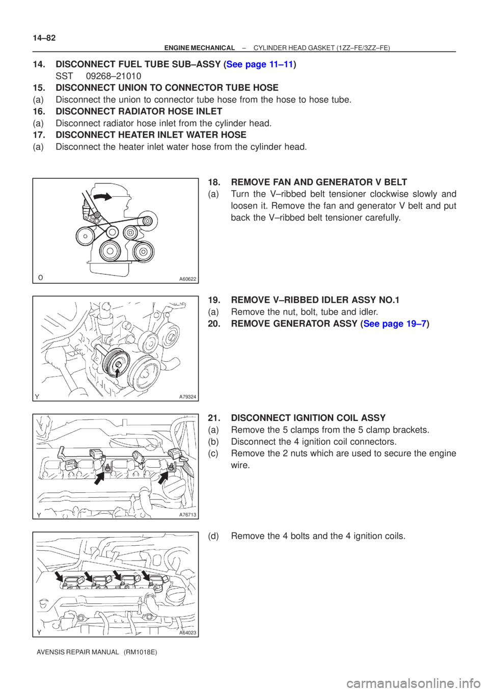
18.REMOVE FAN AND GENERATOR V BELT
(a)Turn the V±ribbed belt tensioner clockwise slowly andloosen it. Remove the fan and generator V belt and put
back the V±ribbed belt tensioner carefully.
19.REMOVE V±RIBBED IDLER ASSY NO.1
(a)Remove the nut, bolt, tube and idler.
20.REMOVE GENERATOR ASSY (See page 19±7)
21. DISCONNECT IGNITION COIL ASSY
(a) Remove the 5 clamps from the 5 clamp brackets.
(b) Disconnect the 4 ignition coil connectors.
(c) Remove the 2 nuts which are used to secure the engine wire.
(d) Remove the 4 bolts and the 4 ignition coils.
Page 2123 of 5135
141CL±01
A79321
Clip
Engine Room Side Cover RH
Retainer Clip
Radiator Cover Assy
Clip
Engine Under Cover RH
Engine Under Cover No. 1
Clip
14±76
± ENGINE MECHANICALCYLINDER HEAD GASKET (1ZZ±FE/3ZZ±FE)
AVENSIS REPAIR MANUAL (RM1018E)
CYLINDER HEAD GASKET (1ZZ±FE/3ZZ±FE)
COMPONENTS
Page 2124 of 5135
A76711
Fan and Generator V Belt
Generator Assy Terminal Cap
No. 1
Cylinder Head Cover No. 2 Clip
Fuel Pipe Clamp
Fuel Tube Sub±assy
Water By±pass Hose
Water By±pass Hose No. 2
Accelerator Control
Cable Assy
Heater Inlet Water Hose
Radiator Hose Inlet
Air Cleaner Hose No. 1
� GasketExhaust pipe Assy Front
Compression Spring43 (440, 32)
43 (440, 32)Compression Spring
� Non±reusable part
N´m (kgf´cm, ft´lbf) : Specified torque
V±ribbed idler Assy No. 1
Tube
54 (551, 40)
9.8 (100, 7)
25 (255, 18)
39 (400, 29)
7.0 (71, 62 in.�lbf)
52 (530, 38)
52 (530, 38)
Union to Connector Tube Hose
Fuel Vapor Feed Hose No.1
Fuel Vapor Feed Hose No.3
Vacuum Hose Assy
Engine
Mounting
Insulator RH
VSV Connector
Mass Air Flow Meter Connector
± ENGINE MECHANICALCYLINDER HEAD GASKET (1ZZ±FE/3ZZ±FE)
14±77
AVENSIS REPAIR MANUAL (RM1018E)
Page 2133 of 5135
141BH±01
A77281
A13697
SST
SST
A77381
SST
14±178
±
ENGINE MECHANICAL TIMING GEAR CASE OR TIMING CHAIN CASE OIL
SEAL(1AZ±FE)
AVENSIS REPAIR MANUAL (RM1018E)
TIMING GEAR CASE OR TIMING CHAIN CASE OIL
SEAL(1AZ±FE)
REPLACEMENT
1.REMOVE FRONT WHEEL RH
2.REMOVE RADIATOR SUPPORT OPENING COVER
3.REMOVE ENGINE ROOM COVER SIDE
4.REMOVE ENGINE UNDER COVER RH 5.REMOVE ENGINE COVER SUB±ASSY NO.1
(a)Remove the 2 nuts and the engine cover No. 1.
6.REMOVE FAN AND GENERATOR V BELT (See page 14±105) SST 09249±63010
7. REMOVE CRANKSHAFT PULLEY
(a) Using SST, loosen the pulley bolt.SST 09213±54015 (91651±60855), 09330±00021,
(b) Using SST, remove the crankshaft pulley. SST 09950±50013 (09951±05010, 09952±05010, 09953±05020, 09954±05021)
Page 2135 of 5135
141BK±01
A77281
A77283
A77284
± ENGINE MECHANICALCAMSHAFT (1AZ±FE)
14±171
AVENSIS REPAIR MANUAL (RM1018E)
REPLACEMENT
1. REMOVE RADIATOR SUPPORT OPENING COVER
2. REMOVE ENGINE ROOM COVER SIDE
3. REMOVE ENGINE UNDER COVER RH
4. REMOVE ENGINE COVER SUB±ASSY NO.1
(a) Remove the 2 nuts and the engine cover No. 1.
5. REMOVE IGNITION COIL ASSY
(a) Remove 4 bolts and the ignition coils.
6. REMOVE CYLINDER HEAD COVER SUB±ASSY
(a) Disconnect the 2 PCV hoses from the cylinder head cov-
er.
(b) Remove the 8 bolts and 2 nuts, and then remove the cylin-
der head cover and gasket.
7. SET NO. 1 CYLINDER TO TDC/COMPRESSION
(a) Turn the crankshaft pulley, and align its timing notch with
timing mark 0 of the timing chain cover.
Page 2142 of 5135
141BG±01
A77322
7.0 (71.62, in.�lbf)
7.0 (71.62, in.�lbf)
Engine Room
Cover Side
Radiator Support
Opening CoverEngine Cover Sub±assy No. 1
Engine Under Cover RH
N´m (kgf´cm, ft´lbf)
: Specified torque 14±168
± ENGINE MECHANICALCAMSHAFT (1AZ±FE)
AVENSIS REPAIR MANUAL (RM1018E)
CAMSHAFT (1AZ±FE)
COMPONENTS