Page 1908 of 5135
110UB±01
A79437
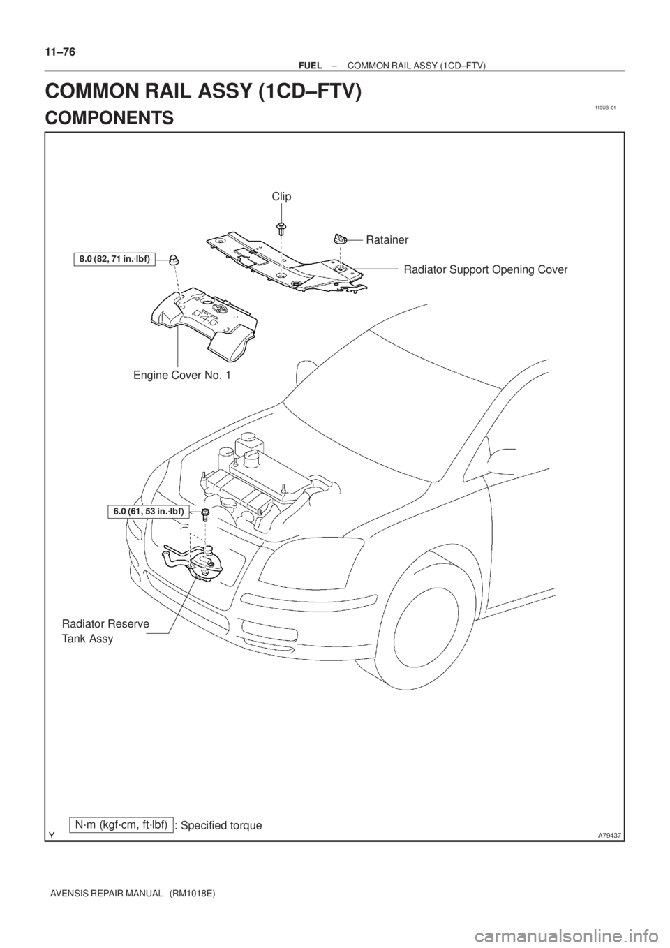
8.0 (82, 71 in.�lbf)
Engine Cover No. 1Radiator Support Opening Cover
N´m (kgf´cm, ft´lbf)
: Specified torque
6.0 (61, 53 in.�lbf)
Radiator Reserve
Tank Assy
Clip
Ratainer
11±76
± FUELCOMMON RAIL ASSY (1CD±FTV)
AVENSIS REPAIR MANUAL (RM1018E)
COMMON RAIL ASSY (1CD±FTV)
COMPONENTS
Page 1910 of 5135

11±69
AVENSIS REPAIR MANUAL (RM1018E)
REPLACEMENT
1.REMOVE FRONT WHEEL RH
2.DRAIN ENGINE COOLANT(See page 16±44)
3.REMOVE ENGINE UN")
110UA±01
A15950
±
FUEL INJECTION OR SUPPLY PUMP ASSY(1CD±FTV)
11±69
AVENSIS REPAIR MANUAL (RM1018E)
REPLACEMENT
1.REMOVE FRONT WHEEL RH
2.DRAIN ENGINE COOLANT(See page 16±44)
3.REMOVE ENGINE UNDER COVER SUB±ASSY NO.1
4.REMOVE ENGINE UNDER COVER RH
5.REMOVE RADIATOR SUPPORT OPENING COVER
6.REMOVE ENGINE ROOM COVER SIDE
7.REMOVE AIR CLEANER ASSY (See page 11±60)
8.REMOVE ENGINE COVER NO.1
(a)Remove the 5 nuts and the engine cover.
9.REMOVE RADIATOR RESERVE TANK ASSY(See page 16±50)
10.DISCONNECT RADIATOR HOSE OUTLET
(a)Disconnect the radiator hose outlet from the water inlet.
11.REMOVE V (COOLER COMPRESSOR TO CRANKSHAFT PULLEY) BELT NO.1
(See page 14±269)
12.REMOVE GENERATOR V BELT (See page 14±269)
13.REMOVE INJECTOR DRIVER
(a)Remove the 2 nuts which are used to secure the injector driver.
(b)Disconnect the injector driver connector and the harness clamp.
(c)Remove the injector driver.
14.REMOVE ENGINE MOUNTING INSULATOR SUB±ASSY RH(See page 14±307)
15.REMOVE CRANKSHAFT PULLEY(See page 14±307)
SST09213±54015 (90105±08076), 09330±00021, 09950±50013 (0995\
1±05010, 09952±05010, 09953±05020, 09954±05031)
16.REMOVE IDLER PULLEY SUB±ASSY
(a)Remove the bolt and washer, then remove the idler pulley.
17.REMOVE TIMING BELT NO.2 COVER(See page 14±307)
18.REMOVE TIMING BELT NO.1 COVER(See page 14±307)
19. REMOVE TIMING BELT GUIDE
20. REMOVE TRANSVERSE ENGINE ENGINE MOUNTING BRACKET
(a) Remove the 6 bolts and the engine mounting bracket.
21.SET NO. 1 CYLINDER TO TDC/COMPRESSION(See page 14±307)
22.REMOVE TIMING CHAIN COVER PLATE(See page 14±307)
23.REMOVE TIMING BELT(See page 14±307)
Page 1916 of 5135

11±75
AVENSIS REPAIR MANUAL (RM1018E)
52.INSTALL TIMING BELT GUIDE(See page 14±307)
53.INSTALL TIMING BELT NO.1 COVER(See page 14±307)
54.INSTALL")
±
FUEL INJECTION OR SUPPLY PUMP ASSY (1CD±FTV)
11±75
AVENSIS REPAIR MANUAL (RM1018E)
52.INSTALL TIMING BELT GUIDE(See page 14±307)
53.INSTALL TIMING BELT NO.1 COVER(See page 14±307)
54.INSTALL TIMING BELT NO.2 COVER(See page 14±307)
55. INSTALL IDLER PULLEY SUB±ASSY
Torque: 40 N �m (408 kgf �cm, 30 ft �lbf)
56.INSTALL CRANKSHAFT PULLEY(See page 14±307) SST 09213±54015 (90105±08076), 09330±00021
57.INSTALL ENGINE MOUNTING INSULATOR SUB±ASSY RH(See page 14±307)
58. INSTALL INJECTOR DRIVER Torque: 5.0 N �m (51 kgf �cm, 44 in. �lbf)
59. ADJUST V (COOLER COMPRESSOR TO CRANKSHAFT PULLEY) BELT NO.1 (See page 14±269)
60.INSTALL RADIATOR RESERVE TANK ASSY(See page 16±50)
61. INSTALL ENGINE COVER NO.1 Torque: 8.0 N �m (82 kgf �cm, 71 in. �lbf)
62.INSTALL AIR CLEANER ASSY (See page 11±60)
63. INSTALL FRONT WHEEL RH
Torque: 103 N �m (1,050 kgf �cm, 76 ft �lbf)
64.ADD ENGINE COOLANT(See page 16±44)
65.CHECK FOR ENGINE COOLANT LEAKS(See page 16±37)
66.CHECK FOR FUEL LEAKS(See page 11±60)
Page 1917 of 5135
110U9±01
A79435
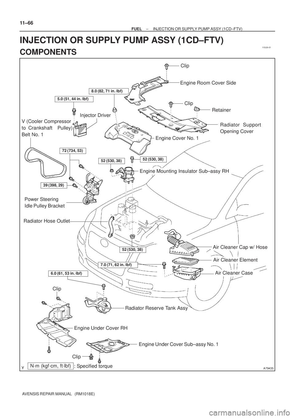
Air Cleaner Cap w/ Hose
Air Cleaner Element
Air Cleaner Case
7.0 (71, 62 in.�lbf)
N´m (kgf´cm, ft´lbf)
: Specified torque
Radiator Hose Outlet
Clip
Engine Room Cover Side
Clip
Retainer
Radiator Support
Opening Cover
8.0 (82, 71 in.�lbf)
5.0 (51, 44 in.�lbf)
V (Cooler Compressor
to Crankshaft Pulley)
Belt No. 1
Injector Driver
72 (734, 53)
52 (530, 38)52 (530, 38)
Engine Cover No. 1
Engine Mounting Insulator Sub±assy RH
39 (398, 29)
Power Steering
Idle Pulley Bracket
52 (530, 38)
Clip
Engine Under Cover RH
Engine Under Cover Sub±assy No. 1
Clip
Radiator Reserve Tank Assy
6.0 (61, 53 in.�lbf)
11±66
± FUELINJECTION OR SUPPLY PUMP ASSY (1CD±FTV)
AVENSIS REPAIR MANUAL (RM1018E)
INJECTION OR SUPPLY PUMP ASSY (1CD±FTV)
COMPONENTS
Page 1920 of 5135

AVENSIS REPAIR MANUAL (RM1018E)
REPLACEMENT
HINT:
Each injector assembly has a characteristic fuel injecting behavior. The ECM stores comp")
110U8±01
A79143
SST
11±60
±
FUEL INJECTOR ASSY(1CD±FTV)
AVENSIS REPAIR MANUAL (RM1018E)
REPLACEMENT
HINT:
Each injector assembly has a characteristic fuel injecting behavior. The ECM stores compensation codes
which are used to optimize fuel injection for the injectors. When replacing t\
he injector assembly, a compensa-
tion code for the new injector assembly must be set to the ECM.
1.REMOVE VACUUM RESERVOIR SUB±ASSY
(a)Disconnect the 2 vacuum hoses and the connector.
(b)Remove the 2 bolts and the vacuum reservoir.
2.REMOVE RADIATOR SUPPORT OPENING COVER
3.REMOVE ENGINE COVER NO.1
(a)Remove the 5 nuts and the engine cover.
4.REMOVE AIR CLEANER ASSY
(a)Disconnect the connector.
(b)Remove the air cleaner cap with the air cleaner hose.
(c)Remove the air cleaner filter element.
(d)Remove the 3 bolts and the air cleaner case.
5.REMOVE AIR TUBE NO.1 (See page 14±270) 6. REMOVE INJECTION PIPE SUB±ASSY NO.1
(a) Remove the 2 nuts and 2 upper infection pipe clampsfrom the intake manifold.
(b) Using SST, remove the injection pipe from the common rail side.
SST 09023±12700
(c) Using SST, remove the injection pipe from the injector side.
SST 09023±12700
(d) After removing the fuel pipe, to prevent dust or foreign ob- jects from being introduced, cover the common rail with
vinyl tape and protect the injector inlet with a vinyl or plas-
tic bag.
7. REMOVE INJECTION PIPE SUB±ASSY NO.2
SST 09023±12700
HINT:
Perform the same procedures as injection pipe No. 1.
8. REMOVE INJECTION PIPE SUB±ASSY NO.3 SST 09023±12700
HINT:
Perform the same procedures as injection pipe No. 1.
9. REMOVE INJECTION PIPE SUB±ASSY NO.4 SST 09023±12700
HINT:
Perform the same procedures as injection pipe No. 1.
10. REMOVE TIMING BELT NO.2 COVER
(a) Remove the 7 bolts and 7 seal washers, then remove the timing belt cover\
.
Page 1926 of 5135
110U7±01
A79434
Radiator Support Opening Cover
Engine Cover No. 1
Vacuum Reservoir Sub±assy
Union To Connector Tube Hose
Air Cleaner Cap w/ Hose
Air Cleaner Element
Air Cleaner Case
N´m (kgf´cm, ft´lbf)
: Specified torque
8.0 (82, 71 in.�lbf)
8.3 (85, 73 in.�lbf)
7.0 (71, 62 in.�lbf)
Clip
Retainer
25 (255, 18)
Air Tube No. 1
25 (255, 18)
11±58
± FUELINJECTOR ASSY (1CD±FTV)
AVENSIS REPAIR MANUAL (RM1018E)
INJECTOR ASSY (1CD±FTV)
COMPONENTS
Page 1930 of 5135

AVENSIS REPAIR MANUAL (RM1018E)
REPLACEMENT
1.DISCHARGE FUEL SYSTEM PRESSURE (See page 11±30)
2.REMOVE RADIATOR SUP")
110TB±01
A79569
A79570
SST
A79571
A79572
11±52
±
FUEL FUEL PUMP ASSY(1AZ±FSE)
AVENSIS REPAIR MANUAL (RM1018E)
REPLACEMENT
1.DISCHARGE FUEL SYSTEM PRESSURE (See page 11±30)
2.REMOVE RADIATOR SUPPORT OPENING COVER (See page 18±16)
3.REMOVE ENGINE COVER SUB±ASSY NO.1 (See page 10±44)
4.REMOVE AIR CLEANER CAP SUB±ASSY (See page 10±44) 5.REMOVE ENGINE COVER BRACKET
(a)Remove the bolt and the engine cover bracket.
6.REMOVE FUEL PRESSURE PULSATION DAMPERASSY
(a)Disconnect the fuel tube sub±assy. (See page 11±30)
(b) Using SST, remove the fuel pressure pulsation damper assy, the fuel tube sub±assy and the 2 gasket.
SST 09617±24011
7. REMOVE FUEL PIPE SUB±ASSY NO.1
(a) Remove the fuel hose.
(b) Clamp the union bolt on the fuel pump assy with a 21 mm wrench and remove the fuel pipe sub±assy No. 1 from the
fuel pump assy using a 19 mm union±nut wrench.
NOTICE:
Do not loosen the union bolt on the fuel pump assy. If it be-
come loose, replace the fuel pump assy with new fuel
pump assy.
Page 1933 of 5135
±
FUEL FUEL PUMP ASSY(1AZ±FSE)
11±55
AVENSIS REPAIR MANUAL (RM1018E)
12.INSTALL ENGINE COVER BRACKET
(a)Install the engine cover bracket with the bolt.
Torque: 38 N �m (388 kgf �cm, 28 ft �lbf)
13.INSTALL AIR CLEANER CAP SUB±ASSY (See page 10±44)
14. CHECK FOR FUEL LEAKS
15. INSTALL ENGINE COVER SUB±ASSY NO.1 Torque: 7.0 N �m (71 kgf �cm, 62 in. �lbf)
16. INSTALL RADIATOR SUPPORT OPENING COVER