Page 1864 of 5135
100FO±01
A80092
B08171
A64328
2 to 7 mm0 to 4 mm
± ENGINE CONTROL SYSTEMINTAKE SHUTTER ASSY (1CD±FTV)
10±61
AVENSIS REPAIR MANUAL (RM1018E)
Removal & Installation and Disassembly & Reassembly
1. REMOVE RADIATOR SUPPORT OPENING COVER
2. REMOVE ENGINE COVER NO.1
(a) Remove the 5 nuts and the engine cover.
3. REMOVE BATTERY
4. REMOVE AIR HOSE NO.4
(a) Loosen the 2 hose clamps.
(b) Remove the 2 bolts and separate the air tube No. 2.
(c) Remove the air hose No. 4.
5. REMOVE INTAKE SHUTTER ASSY
(a) Disconnect the 2 connectors.
(b) Remove the 3 nuts, then remove the intake shutter and
the gasket.
6. INSTALL INTAKE SHUTTER ASSY
(a) Install a new gasket and the intake shutter with the 3 nuts.
Torque: 21 N�m (214 kgf�cm, 15 ft�lbf)
7. INSTALL AIR HOSE NO.4
(a) Install the air hose No. 4 to the air tube No. 2.
(b) Install the air tube No. 2 with the 2 bolts.
Torque: 25 N�m (255 kgf�cm, 18 ft�lbf)
(c) Install the air hose and hose clamp as shown in the il-
lustration.
Page 1866 of 5135
100FN±01
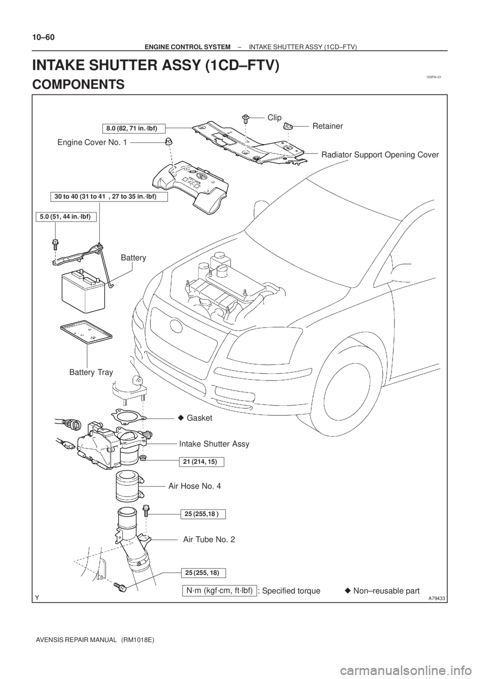
A79433N´m (kgf´cm, ft´lbf)
: Specified torque� Non±reusable part � Gasket
25 (255, 18)
25 (255,18 )
21 (214, 15)
30 to 40 (31 to 41 , 27 to 35 in.�lbf)
5.0 (51, 44 in.�lbf)
8.0 (82, 71 in.�lbf)
Radiator Support Opening Cover Engine Cover No. 1
Battery
Battery Tray
Intake Shutter Assy
Air Hose No. 4
Clip
Retainer
Air Tube No. 2
10±60
± ENGINE CONTROL SYSTEMINTAKE SHUTTER ASSY (1CD±FTV)
AVENSIS REPAIR MANUAL (RM1018E)
INTAKE SHUTTER ASSY (1CD±FTV)
COMPONENTS
Page 1867 of 5135
110TA±01
A78507
Mass Air Flow
Meter Connector
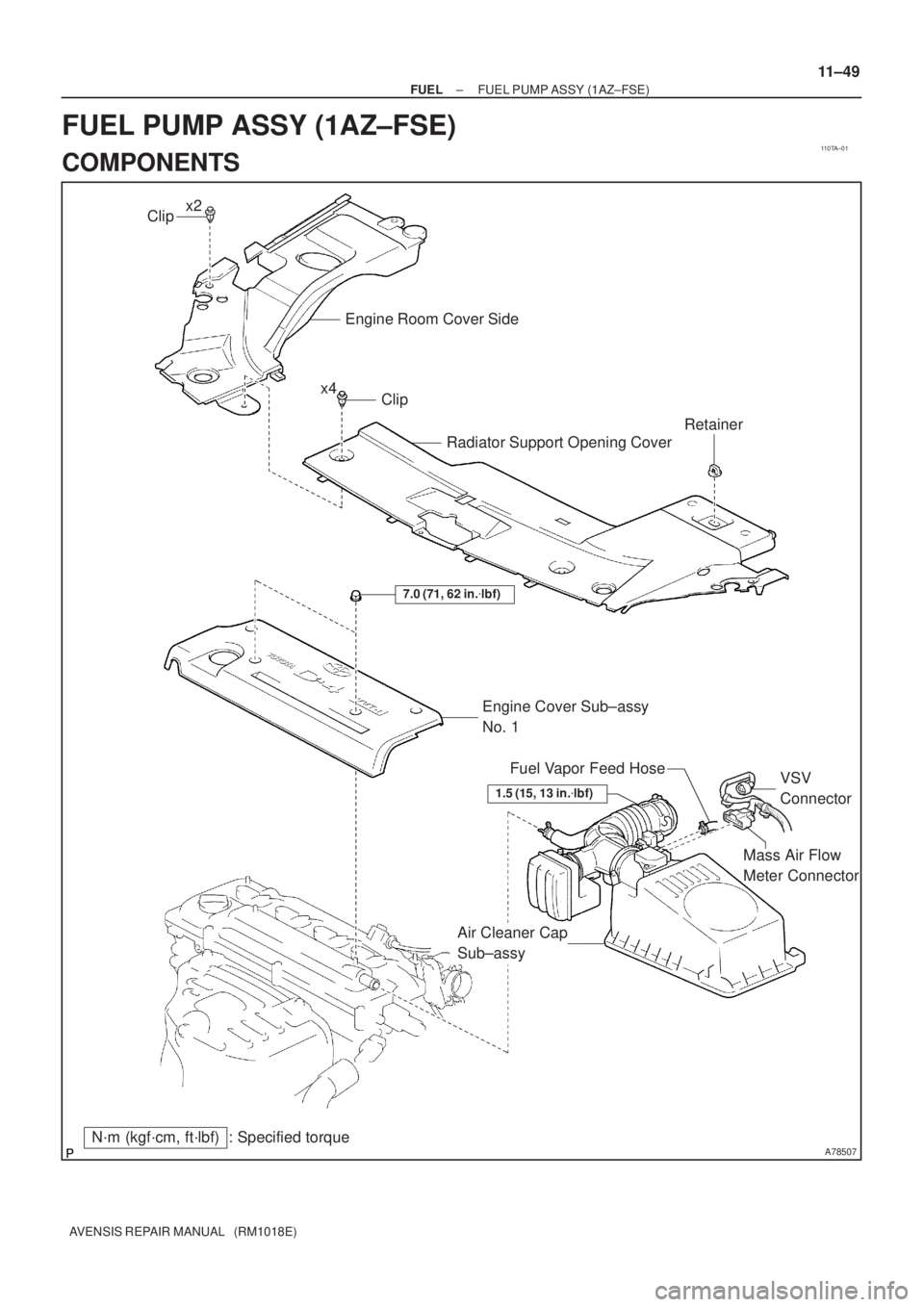
N´m (kgf´cm, ft´lbf) : Specified torqueEngine Cover Sub±assy
No. 1
7.0 (71, 62 in.�lbf)
Air Cleaner Cap
Sub±assyVSV
Connector Fuel Vapor Feed Hose
Clip
Engine Room Cover Side
Radiator Support Opening Cover
Clip
Retainer
x2
x4
1.5 (15, 13 in.�lbf)
± FUELFUEL PUMP ASSY (1AZ±FSE)
11±49
AVENSIS REPAIR MANUAL (RM1018E)
FUEL PUMP ASSY (1AZ±FSE)
COMPONENTS
Page 1870 of 5135
110TD±01
A79578
A79579
A79580
11±42
±
FUEL FUEL INJECTOR ASSY (1AZ±FSE)
AVENSIS REPAIR MANUAL (RM1018E)
REPLACEMENT
1.DISCHARGE FUEL SYSTEM PRESSURE (See page 11±30)
2.REMOVE RADIATOR SUPPORT OPENING COVER (See page 18±16)
3.REMOVE ENGINE ROOM COVER SIDE (See page 18±17)
4.REMOVE ENGINE COVER SUB±ASSY NO.1 (See page 10±44)
5.DRAIN ENGINE COOLANT (See page 16±31)
6.REMOVE AIR CLEANER CAP SUB±ASSY (See page 10±44)
7.REMOVE THROTTLE BODY ASSY (See page 10±44)
8. REMOVE CHARCOAL CANISTER ASSY
9.REMOVE ENGINE COVER BRACKET (See page 11±52)
10.REMOVE FUEL PUMP ASSY(See page 11±52) 11. REMOVE INTAKE MANIFOLD
(a) Remove the ventilation hose No. 1.
(b) Disconnect the 2 vacuum hoses from the VSV.
(c) Disconnect the union to connector tube hose from thebrake booster assy.
(d) Remove the 5 bolts and 2 nuts from the intake manifold.
Page 1876 of 5135
11±48
±
FUEL FUEL INJECTOR ASSY(1AZ±FSE)
AVENSIS REPAIR MANUAL (RM1018E)
26.INSTALL THROTTLE BODY ASSY (See page 10±44)
27.INSTALL AIR CLEANER CAP SUB±ASSY (See page 10±44)
28.ADD ENGINE COOLANT (See page 16±31)
29.CHECK FOR ENGINE COOLANT LEAKS (See page 16±25)
30. CHECK FOR FUEL LEAKS
31. INSTALL ENGINE COVER SUB±ASSY NO.1 Torque: 7.0 N �m (71 kgf �cm, 62 in. �lbf)
32. INSTALL ENGINE ROOM COVER SIDE
33. INSTALL RADIATOR SUPPORT OPENING COVER
Page 1877 of 5135
110TC±01
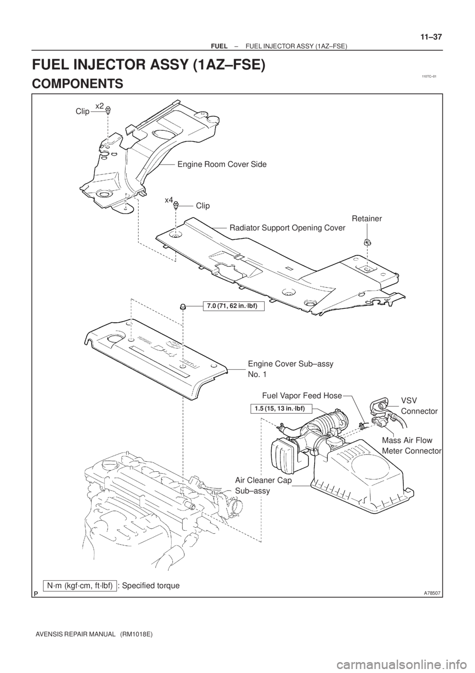
A78507
Mass Air Flow
Meter Connector
N´m (kgf´cm, ft´lbf) : Specified torqueEngine Cover Sub±assy
No. 1
7.0 (71, 62 in.�lbf)
Air Cleaner Cap
Sub±assyVSV
Connector Fuel Vapor Feed Hose
Clip
Engine Room Cover Side
Radiator Support Opening Cover
Clip
Retainer
x2
x4
1.5 (15, 13 in.�lbf)
± FUELFUEL INJECTOR ASSY (1AZ±FSE)
11±37
AVENSIS REPAIR MANUAL (RM1018E)
FUEL INJECTOR ASSY (1AZ±FSE)
COMPONENTS
Page 1904 of 5135

AVENSIS REPAIR MANUAL (RM1018E)
REPLACEMENT
1.DRAIN ENGINE COOLANT(See page 16±44)
2. REMOVE RADIATOR SUPPORT OPENING COVER")
110UC±01
A79148
SST
A79143
SST
11±78
±
FUEL COMMON RAIL ASSY(1CD±FTV)
AVENSIS REPAIR MANUAL (RM1018E)
REPLACEMENT
1.DRAIN ENGINE COOLANT(See page 16±44)
2. REMOVE RADIATOR SUPPORT OPENING COVER
3. REMOVE ENGINE COVER NO.1
(a) Remove the 5 nuts and the engine cover.
4.REMOVE RADIATOR RESERVE TANK ASSY(See page 16±50) 5. REMOVE FUEL INLET PIPE SUB±ASSY
NOTICE:
After removing the fuel inlet pipe, cover the common rail
and the injection pump with vinyl tape to prevent dust from
being introduced.
(a) Using SST, remove the fuel inlet pipe from the commonrail.
SST 09023±12700
(b) Using SST, remove the fuel inlet pipe from the injection pump.
SST 09023±12700
6. REMOVE INJECTION PIPE SUB±ASSY NO.1
(a) Remove the 2 nuts and the 2 upper infection pipe clamps from the intake manifold.
(b) Using SST, remove the injection pipe from the common
rail side.
SST 09023±12700
(c) Using SST, remove the injection pipe from the injector side.
SST 09023±12700
(d) After removing the fuel pipe, to prevent dust or foreign ob- jects from being introduced, cover the common rail with
vinyl tape and protect the injector inlet with a vinyl or plas-
tic bag.
7. REMOVE INJECTION PIPE SUB±ASSY NO.2 SST 09023±12700
HINT:
Perform the same procedures as injection pipe No. 1.
8. REMOVE INJECTION PIPE SUB±ASSY NO.3 SST 09023±12700
HINT:
Perform the same procedures as injection pipe No. 1.
Page 1907 of 5135

SST
±
FUEL COMMON RAIL ASSY(1CD±FTV)
11±81
AVENSIS REPAIR MANUAL (RM1018E)
19.INSTALL FUEL INLET PIPE SUB±ASSY
NOTICE:
�In case of having the common rail replaced, must")
A79149
30 cm
(11.81 in.)
SST
±
FUEL COMMON RAIL ASSY(1CD±FTV)
11±81
AVENSIS REPAIR MANUAL (RM1018E)
19.INSTALL FUEL INLET PIPE SUB±ASSY
NOTICE:
�In case of having the common rail replaced, must re-
place fuel inlet pipe, too.
�When assembling the pipe, perform the operation
with the engine cold under room temperature.
(a)Temporarily install the fuel inlet pipe.
(b)Using SST, tighten the nut of the fuel inlet pipe to the com-
mon rail side.
SST09023±12700
Torque:
42 N�m (428 kgf �cm, 31 ft �lbf) for a used pipe using SST
46 N �m (469 kgf �cm, 34 ft �lbf) for a used pipe not using
SST
31 N �m (316 kgf �cm, 23 ft �lbf) for a new pipe using SST
34 N �m (347 kgf �cm, 25 ft �lbf) for a new pipe not using
SST
HINT:
�Use a torque wrench with a fulcrum length of 30 cm
(11.81 in.)
�Check if the used pipe has deflection or is installed prop-
erly after inlet pipe is reassembled. If there is deflection
or if it can not be installed properly, replace the used pipe
with a new pipe.
(c)Using SST, tighten the nut of the fuel inlet pipe to the injec-
tion pump side.
SST09023±12700
Torque:
42 N�m (428 kgf �cm, 31 ft �lbf) for a used pipe using SST
46 N �m (469 kgf �cm, 34 ft �lbf) for a used pipe not using
SST
31 N �m (316 kgf �cm, 23 ft �lbf) for a new pipe using SST
34 N �m (347 kgf �cm, 25 ft �lbf) for a new pipe not using
SST
HINT:
�Use a torque wrench with a fulcrum length of 30 cm
(11.81 in.)
�Check if the used pipe has deflection or is installed prop-
erly after inlet pipe is reassembled. If there is deflection
or if it can not be installed properly, replace the used pipe
with a new pipe.
20.INSTALL RADIATOR RESERVE TANK ASSY(See page 16±50)
21. INSTALL ENGINE COVER NO.1 Torque: 8.0 N �m (82 kgf �cm, 71 in. �lbf)
22.ADD ENGINE COOLANT(See page 16±44)
23.CHECK FOR ENGINE COOLANT LEAKS(See page 16±37)
24.CHECK FOR FUEL LEAKS(See page 11±60)

10±61
AVENSIS REPAIR MANUAL (RM1018E)
Removal & Installation and Disassembly & Reassembly
1.")

AVENSIS REPAIR MANUAL (RM1018E)
REPLACEMENT
1.DISCHARGE FUEL SYSTEM PRESSURE (See page 11±30)
2.REMOVE RADIATOR SUPPORT O")

AVENSIS REPAIR MANUAL (RM1018E)
26.INSTALL THROTTLE BODY ASSY (See page 10±44)
27.INSTALL AIR CLEANER CAP SUB±ASSY (See page 10±44)
28.ADD ENGINE COOLA")