Page 2232 of 5135
141BJ±01
A77423
SST
± ENGINE MECHANICALFAN AND GENERATOR V BELT (1AZ±FSE)
14±185
AVENSIS REPAIR MANUAL (RM1018E)
FAN AND GENERATOR V BELT (1AZ±FSE)
REPLACEMENT
1. REMOVE RADIATOR SUPPORT OPENING COVER
2. REMOVE ENGINE ROOM COVER SIDE
3. REMOVE ENGINE UNDER COVER RH
4. REMOVE FAN AND GENERATOR V BELT
(a) Using SST, loosen the V±ribbed belt tensioner arm clock-
wise, and remove the fan and generator V belt.
SST 09249±63010
5. INSTALL FAN AND GENERATOR V BELT
(a) Using SST, loosen the V±ribbed belt tensioner arm clockwise, and install the fan and generator V belt.
SST 09249±63010
Page 2233 of 5135
141C3±01
A79198N´m (kgf´cm, ft´lbf)
: Specified torque
5.0 (51, 44 in.�lbf)
19 (194, 14)
3.0 to 4.0 (31 to 41, 27 to 35 in.�lbf)
7.0 (71, 62 in.�lbf)
5.3 (54, 47in.�lbf)
Engine Room Relay Block No. 3
8.0 (82, 71 in.�lbf)
Engine Room Cover Side
Radiator Support Opening Cover
Radiator Support Upper
Radiator Hose Inlet
Engine Cover No. 1
Radiator Hose Outletw/ A/C:
Radiator Assy
Battery
Battery Tray
Engine Under Cover RHEngine Under Cover Sub±assy No. 1
Engine Under Cover LH
Air Cleaner Cap w/ Hose
Air Cleaner Element
Air Cleaner Case
Clip
Clip
Clip
Retainer
Clip
Clip
± ENGINE MECHANICALPARTIAL ENGINE ASSY (1CD±FTV)
14±277
AVENSIS REPAIR MANUAL (RM1018E)
PARTIAL ENGINE ASSY (1CD±FTV)
COMPONENTS
Page 2242 of 5135

141C2±01
A78277
A79143
SST
14±270
±
ENGINE MECHANICAL VALVE CLEARANCE(1CD±FTV)
AVENSIS REPAIR MANUAL (RM1018E)
VALVE CLEARANCE(1CD±FTV)
ADJUSTMENT
NOTICE:
�Before removing the injection pipes, clean them up with a soft brush and compr\
essed air.
�After removing the injection pipe, cover the supply pump, the common rail and the injector
mounting area of the cylinder head cover with vinyl tape to prevent dust from being introduce\
d.
�After removing the cylinder head cover, protect the injector inlet with a vinyl or a plastic bag
to prevent foreign objects from being introduced.
HINT:
Inspect and adjust the valve clearance when the engine is cold.
1.REMOVE RADIATOR SUPPORT OPENING COVER
2.REMOVE FRONT WHEEL RH
3.REMOVE ENGINE UNDER COVER RH
4.DRAIN ENGINE COOLANT (See page 16±44)
5.REMOVE ENGINE COVER NO.1
(a)Remove the 5 nuts and the engine cover.
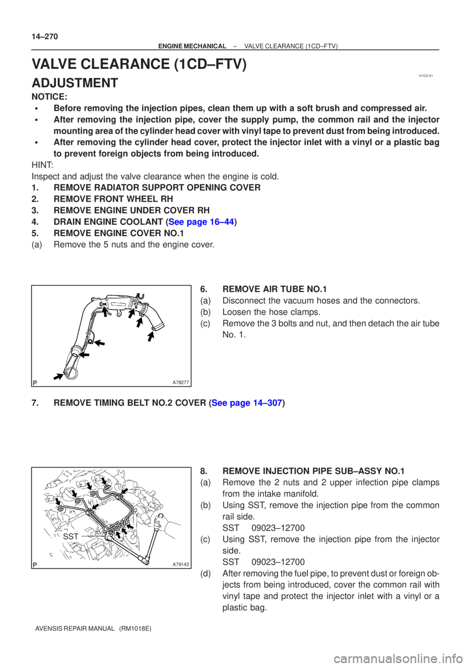
6.REMOVE AIR TUBE NO.1
(a)Disconnect the vacuum hoses and the connectors.
(b)Loosen the hose clamps.
(c)Remove the 3 bolts and nut, and then detach the air tubeNo. 1.
7.REMOVE TIMING BELT NO.2 COVER (See page 14±307) 8. REMOVE INJECTION PIPE SUB±ASSY NO.1
(a) Remove the 2 nuts and 2 upper infection pipe clampsfrom the intake manifold.
(b) Using SST, remove the injection pipe from the common rail side.
SST 09023±12700
(c) Using SST, remove the injection pipe from the injector
side.
SST 09023±12700
(d) After removing the fuel pipe, to prevent dust or foreign ob- jects from being introduced, cover the common rail with
vinyl tape and protect the injector inlet with a vinyl or a
plastic bag.
Page 2249 of 5135
141C1±01
A56434
AB
A56462
A56434
AB
±
ENGINE MECHANICAL DRIVE BELT(1CD±FTV)
14±269
AVENSIS REPAIR MANUAL (RM1018E)
DRIVE BELT(1CD±FTV)
REPLACEMENT
1.REMOVE RADIATOR SUPPORT OPENING COVER
2.REMOVE ENGINE ROOM COVER SIDE
3.REMOVE ENGINE UNDER COVER RH
4.REMOVE V (COOLER CO MPRESSOR TO
CRANKSHAFT PULLEY) BELT NO.1
(a)Loosen nut A and bolt B.
(b)Remove the V±ribbed belt.
5.REMOVE GENERATOR V BELT
(a)Turn the V±ribbed belt tensioner assy clockwise slowly, and remove the V±ribbed belt.
6.ADJUS T V (COOLER CO MPRESSOR TO
CRANKSHAFT PULLEY) BELT NO.1
(a)Install the V±ribbed belt.
(b)Tighten bolt B and adjust the drive belt tension. (See page 14±266)
(c) Tighten nut A. Torque: 38 N �m (390 kgf �cm, 28 ft �lbf)
Page 2254 of 5135
141BR±01
A77339
A13697
SST
SST
A77381
SST
±
ENGINE MECHANICAL TIMING GEAR CASE OR TIMING CHAIN CASE OIL
SEAL(1AZ±FSE)14±263
AVENSIS REPAIR MANUAL (RM1018E)
TIMING GEAR CASE OR TIMING CHAIN CASE OIL
SEAL(1AZ±FSE)
REPLACEMENT
1.REMOVE FRONT WHEEL RH
2.REMOVE RADIATOR SUPPORT OPENING COVER
3.REMOVE ENGINE ROOM COVER SIDE
4.REMOVE ENGINE UNDER COVER RH
5.REMOVE ENGINE COVER SUB±ASSY NO.1
(a)Remove the 2 nuts and the engine cover No. 1.
6.REMOVE FAN AND GENERATOR V BELT (See page 14±185) SST 09249±63010
7. REMOVE CRANKSHAFT PULLEY
(a) Using SST, loosen the pulley bolt.SST 09213±54015 (91651±60855), 09330±00021
(b) Using SST, remove the crankshaft pulley. SST 09950±50013 (09951±05010, 09952±05010, 09953±05020, 09954±05021)
Page 2256 of 5135

141BO±01
A77339
A77292
14±254
±
ENGINE MECHANICAL CYLINDER HEAD GASKET(1AZ±FSE)
AVENSIS REPAIR MANUAL (RM1018E)
REPLACEMENT
1.DISCHARGE FUEL SYSTEM PRESSURE (See page 11±15)
2.REMOVE FRONT WHEEL RH
3.REMOVE RADIATOR SUPPORT OPENING COVER
4.REMOVE ENGINE ROOM COVER SIDE
5.REMOVE ENGINE UNDER COVER RH
6.REMOVE ENGINE UNDER COVER LH
7.DRAIN COOLANT (See page 16±19)
8.DRAIN ENGINE OIL
(a)Install a new gasket and the drain plug after draining engine oil. Torque: 25 N �m (255 kgf �cm,18 ft �lbf)
9.REMOVE ENGINE COVER SUB±ASSY NO.1
(a)Remove the 2 nuts and the engine cover No. 1.
10.REMOVE FUEL PRESSURE PULSATION DAMPER ASSY
11.SEPARATE FUEL TUBE SUB±ASSY (See page 11±33)
12.REMOVE FUEL PIPE SUB±ASSY NO.1 (See page 11±52) SST 09023±12900
13.REMOVE FUEL PUMP ASSY (See page 11±52)
14.REMOVE FAN AND GENERATOR V BELT (See page 14±185) SST 09249±63010
15.REMOVE GENERATOR ASSY (See page 19±20)
16.REMOVE EXHAUST PIPE ASSY FRONT (See page 15±7)
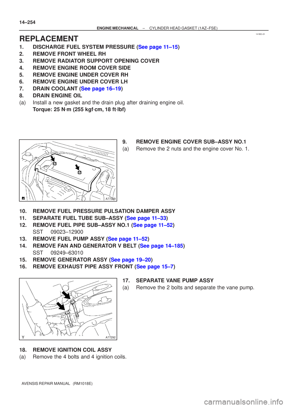
17. SEPARATE VANE PUMP ASSY
(a) Remove the 2 bolts and separate the vane pump.
18. REMOVE IGNITION COIL ASSY
(a) Remove the 4 bolts and 4 ignition coils.
Page 2259 of 5135
A77302
A77353
±
ENGINE MECHANICAL CYLINDER HEAD GASKET(1AZ±FSE)
14±257
AVENSIS REPAIR MANUAL (RM1018E)
(e)Raise a clamp up, and slide it toward the air cleaner cap,
then remove the air cleaner cap from its case.
(f)Remove the air cleaner element.
(g)Remove the 4 bolts and the air cleaner case.
43.DISCONNECT RADIATOR HOSE INLET
44.DISCONNECT UNION TO CONNECTOR TUBE HOSE
45.DISCONNECT HEATER INLET WATER HOSE
46.SEPARATE FUEL TUBE SUB±ASSY
47.SEPARATE ENGINE WIRE
48.REMOVE THROTTLE BODY ASSY (See page 10±44)
49. REMOVE CHARCOAL CANISTER ASSY 50. REMOVE INTAKE MANIFOLD
(a) Remove the 5 bolts and 2 nuts.
(b) Disconnect the 2 vacuum hoses.
(c) Remove the 2 stud bolts.
(d) Remove the intake manifold and insulator.
51. REMOVE INTAKE AIR CONTROL VALVE ASSY
(a) Remove the intake air control valve and gasket.
52. REMOVE MANIFOLD CONVERTER INSULATOR NO.1
(a) Disconnect the oxygen sensor connector.
(b) Remove the 2 bolts and nut, and then remove the manifold insulator.
Page 2265 of 5135
141BN±01
A77310
Engine Room
Cover Side
Radiator Support
Opening CoverEngine Cover Sub±assy No. 1
Fan and Generator V Belt
Engine Under Cover RH
Engine Under Cover LH
7.0 (71, 62 in.�lbf)
7.0 (71, 62 in.�lbf)
N´m (kgf´cm, ft´lbf)
: Specified torque 14±246
± ENGINE MECHANICALCYLINDER HEAD GASKET (1AZ±FSE)
AVENSIS REPAIR MANUAL (RM1018E)
CYLINDER HEAD GASKET (1AZ±FSE)
COMPONENTS