Page 2313 of 5135
141C6±01
A61184
A79179
A61182
SST (B)
SSTSST (A)
±
ENGINE MECHANICAL TIMING BELT(1CD±FTV)
14±307
AVENSIS REPAIR MANUAL (RM1018E)
REPLACEMENT
1.REMOVE FRONT WHEEL RH
2.REMOVE ENGINE UNDER COVER SUB±ASSY NO.1
3.REMOVE ENGINE UNDER COVER RH
4.REMOVE RADIATOR SUPPORT OPENING COVER
5.REMOVE ENGINE ROOM COVER SIDE
6.REMOVE ENGINE COVER NO.1
(a)Remove the 5 nuts and the engine cover.
7.REMOVE INJECTOR DRIVER (See page 14±286)
8.REMOVE V (COOLER COMPRESSOR TO CRANKSHAFT PULLEY) BELT NO.1
(See page 14±269)
9.REMOVE GENERATOR V BELT (See page 14±269)
10.SEPARATE POWER STEERING IDLE PULLEY BRACKET (See page 14±286)
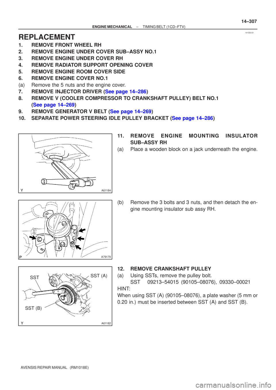
11. REMOVE ENGINE MOUNTING INSULATORSUB±ASSY RH
(a) Place a wooden block on a jack underneath the engine.
(b) Remove the 3 bolts and 3 nuts, and then detach the en- gine mounting insulator sub assy RH.
12. REMOVE CRANKSHAFT PULLEY
(a) Using SSTs, remove the pulley bolt. SST 09213±54015 (90105±08076), 09330±00021
HINT:
When using SST (A) (90105±08076), a plate washer (5 mm or
0.20 in.) must be inserted between SST (A) and SST (B).
Page 2320 of 5135
141C5±01
A79425N´m (kgf´cm, ft´lbf)
: Specified torque
8.0 (82, 71 in.�lbf)
72 (734, 53)
V (Cooler
Compressor to
Crankshaft
Pulley) Belt No. 1
Engine Cover No. 1Engine Room Cover Side
Radiator Support
Opening Cover
Power Steering
Idle Pulley Bracket
Engine Under Cover Sub±assy No. 1
Engine Under Cover RH
Injector Driver
52 (530, 38)
Engine Mounting Insulator Sub±assy RH
52 (530, 38)
52 (530, 38)
39 (398, 29)
Clip
Clip
Retainer
Clip
Clip
5.0 (51, 44 in.�lbf)
± ENGINE MECHANICALTIMING BELT (1CD±FTV)
14±305
AVENSIS REPAIR MANUAL (RM1018E)
TIMING BELT (1CD±FTV)
COMPONENTS
Page 2322 of 5135
141C4±01
A80094
14±286
±
ENGINE MECHANICAL PARTIAL ENGINE ASSY(1CD±FTV)
AVENSIS REPAIR MANUAL (RM1018E)
REPLACEMENT
1.REMOVE FRONT WHEELS
2.REMOVE ENGINE UNDER COVER LH
3.REMOVE ENGINE UNDER COVER SUB±ASSY NO.1
4.REMOVE ENGINE UNDER COVER RH
5.REMOVE RADIATOR SUPPORT OPENING COVER
6.REMOVE ENGINE ROOM COVER SIDE
7.DRAIN ENGINE COOLANT (See page 16±44)
8.DRAIN ENGINE OIL (See page 14±342)
9.DRAIN MANUAL TRANSAXLE OIL Torque: 49 N �m (500 kgf �cm,36 ft �lbf)
10.REMOVE ENGINE COVER NO.1
(a)Remove the 5 nuts and the engine cover.
11.REMOVE BATTERY
12.REMOVE AIR CLEANER ASSY
(a)Disconnect the connector.
(b)Remove the air cleaner cap together with the air cleaner hose.
(c)Remove the air cleaner filter element.
(d)Remove the 3 bolts and the air cleaner case.
13.DISCONNECT UNION TO CONNECTOR TUBE HOSE
14.REMOVE FUEL FILTER ASSY
(a)Disconnect the 2 fuel hose from the fuel filter (STD).
(b)Disconnect the 3 fuel hose from the fuel filter (COLD).
(c)Disconnect the connector (STD).
(d)Disconnect the 2 connectors (COLD).
(e)Remove the 2 bolts and the fuel filter.
15.REMOVE RADIATOR HOSE INLET
16.REMOVE RADIATOR HOSE OUTLET
17.DISCONNECT WATER BY±PASS HOSE NO.2
18.REMOVE ENGINE ROOM RELAY BLOCK NO.3
(a)Remove the 2 bolts and the engine room relay block.
19.REMOVE RADIATOR ASSY (W/ AIR CONDITIONING) (See page 16±51)
20. DISCONNECT HEATER INLET WATER HOSE
21. DISCONNECT HEATER OUTLET WATER HOSE
22. DISCONNECT FUEL HOSE NO.2
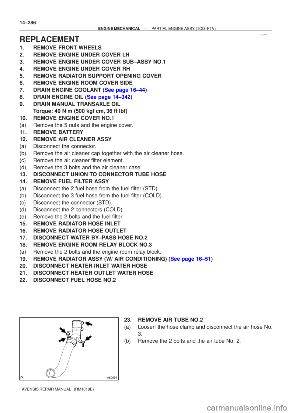
23. REMOVE AIR TUBE NO.2
(a) Loosen the hose clamp and disconnect the air hose No.3.
(b) Remove the 2 bolts and the air tube No. 2.
Page 2339 of 5135
A64328
2 to 7 mm0 to 2 mm
A78274
Upward
90�
Clamp
Bolt
A64328
2 to 7 mm 0 to 4 mm
A64007
Front
90�
Clamp
Bolt
±
ENGINE MECHANICAL PARTIAL ENGINE ASSY(1CD±FTV)
14±303
AVENSIS REPAIR MANUAL (RM1018E)
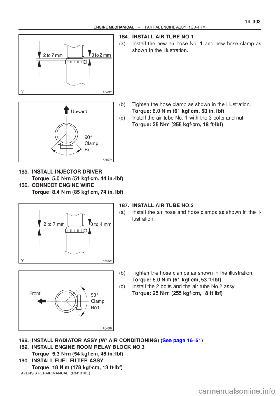
184.INSTALL AIR TUBE NO.1
(a)Install the new air hose No. 1 and new hose clamp as
shown in the illustration.
(b)Tighten the hose clamp as shown in the illustration. Torque: 6.0 N �m (61 kgf �cm, 53 in. �lbf)
(c)Install the air tube No. 1 with the 3 bolts and nut. Torque: 25 N �m (255 kgf �cm, 18 ft �lbf)
185.INSTALL INJECTOR DRIVER Torque: 5.0 N �m (51 kgf �cm,44 in. �lbf)
186.CONNECT ENGINE WIRE Torque: 8.4 N �m (85 kgf �cm,74 in. �lbf)
187.INSTALL AIR TUBE NO.2
(a)Install the air hose and hose clamps as shown in the il- lustration.
(b)Tighten the hose clamps as shown in the illustration. Torque: 6.0 N �m (61 kgf �cm,53 ft �lbf)
(c)Install the 2 bolts and the air tube No.2 assy.
Torque: 25 N �m (255 kgf �cm,18 ft �lbf)
188.INSTALL RADIATOR ASSY (W/ AIR CONDITIONING) (See page 16±51)
189. INSTALL ENGINE ROOM RELAY BLOCK NO.3 Torque: 5.3 N �m (54 kgf �cm, 46 in. �lbf)
190. INSTALL FUEL FILTER ASSY Torque: 18 N �m (178 kgf �cm, 13 ft �lbf)
Page 2341 of 5135
160MV±01
A77341
Radiator Drain Cock Plug Radiator Cap
Cylinder Bllock Drain Cock Plug
Drain Pipe
± COOLINGENGINE COOLANT (1AZ±FE)
16±19
AVENSIS REPAIR MANUAL (RM1018E)
ENGINE COOLANT (1AZ±FE)
REPLACEMENT
1. DRAIN ENGINE COOLANT
CAUTION:
To avoid the danger of being burned, do not remove the ra-
diator cap while the engine and radiator are still hot, as fluid
and steam can be blown out under pressure.
(a) Remove the radiator cap.
(b) Loosen the radiator plug and drain the coolant.
Page 2342 of 5135
16±20
±
COOLING ENGINE COOLANT(1AZ±FE)
AVENSIS REPAIR MANUAL (RM1018E)
2.ADD ENGINE COOLANT
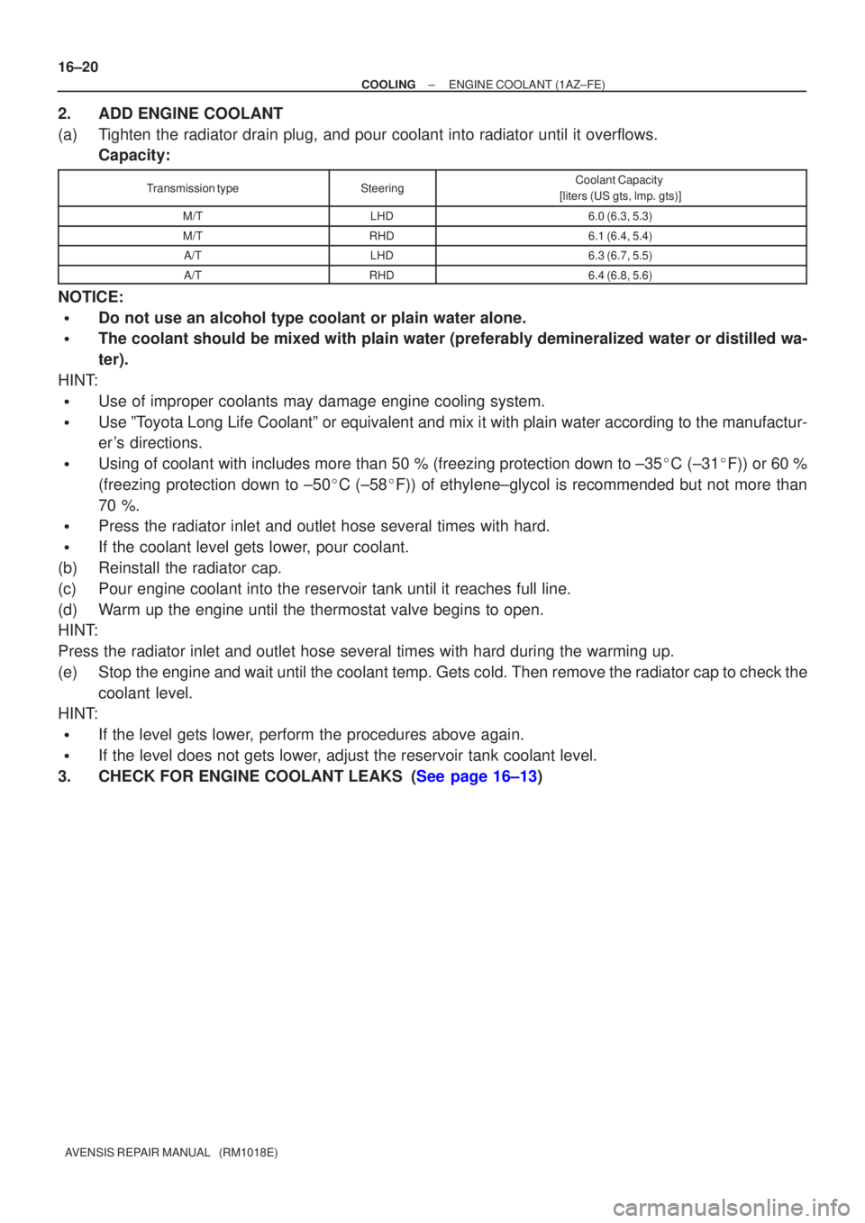
(a)Tighten the radiator drain plug, and pour coolant into radiator until it \
overflows. Capacity:
Transmission typeSteeringCoolant Capacity
[liters (US gts, lmp. gts)]
M/TLHD6.0 (6.3, 5.3)
M/TRHD6.1 (6.4, 5.4)
A/TLHD6.3 (6.7, 5.5)
A/TRHD6.4 (6.8, 5.6)
NOTICE:
�Do not use an alcohol type coolant or plain water alone.
�The coolant should be mixed with plain water (preferably demineralized wat\
er or distilled wa-
ter).
HINT:
�Use of improper coolants may damage engine cooling system.
�Use ºToyota Long Life Coolantº or equivalent and mix it with plain water ac\
cording to the manufactur-
er's directions.
�Using of coolant with includes more than 50 % (freezing protection down to ±\
35 �C (±31 �F)) or 60 %
(freezing protection down to ±50 �C (±58 �F)) of ethylene±glycol is recommended but not more than
70 %.
�Press the radiator inlet and outlet hose several times with hard.
�If the coolant level gets lower, pour coolant.
(b)Reinstall the radiator cap.
(c)Pour engine coolant into the reservoir tank until it reaches full line.
(d)Warm up the engine until the thermostat valve begins to open.
HINT:
Press the radiator inlet and outlet hose several times with hard during \
the warming up.
(e)Stop the engine and wait until the coolant temp. Gets cold. Then remove the radiator cap to check the coolant level.
HINT:
�If the level gets lower, perform the procedures above again.
�If the level does not gets lower, adjust the reservoir tank coolant level.
3.CHECK FOR ENGINE COOLANT LEAKS (See page 16±13)
Page 2345 of 5135
160N2±01
P13560
P00436
10mm
A51911
± COOLINGCOOLING SYSTEM (1AZ±FE)
16±15
AVENSIS REPAIR MANUAL (RM1018E)
INSPECTION
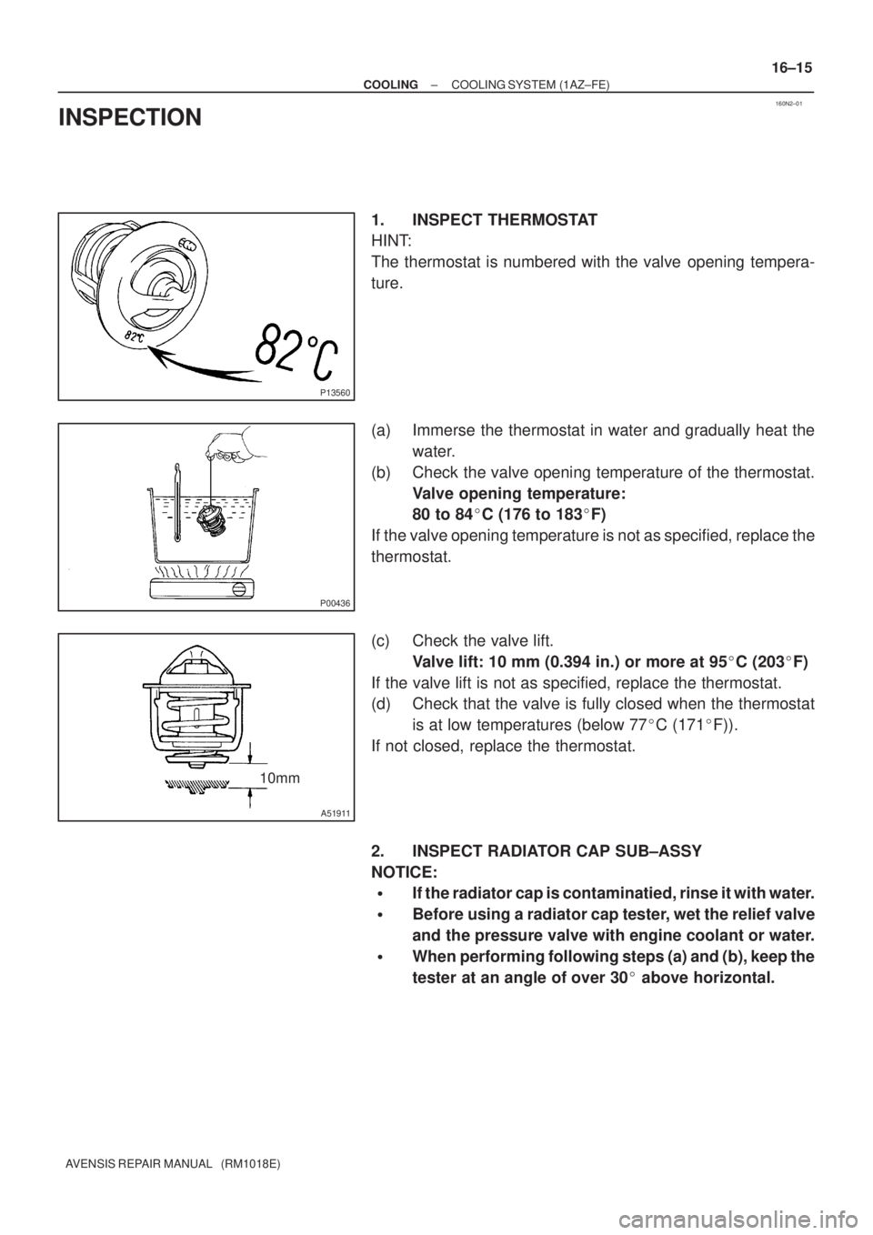
1. INSPECT THERMOSTAT
HINT:
The thermostat is numbered with the valve opening tempera-
ture.
(a) Immerse the thermostat in water and gradually heat the
water.
(b) Check the valve opening temperature of the thermostat.
Valve opening temperature:
80 to 84�C (176 to 183�F)
If the valve opening temperature is not as specified, replace the
thermostat.
(c) Check the valve lift.
Valve lift: 10 mm (0.394 in.) or more at 95�C (203�F)
If the valve lift is not as specified, replace the thermostat.
(d) Check that the valve is fully closed when the thermostat
is at low temperatures (below 77�C (171�F)).
If not closed, replace the thermostat.
2. INSPECT RADIATOR CAP SUB±ASSY
NOTICE:
�If the radiator cap is contaminatied, rinse it with water.
�Before using a radiator cap tester, wet the relief valve
and the pressure valve with engine coolant or water.
�When performing following steps (a) and (b), keep the
tester at an angle of over 30� above horizontal.
Page 2346 of 5135
Radiator CapRadiator Cap Tester
30� or more
A51912
A36661
Turn 16±16
± COOLINGCOOLING SYSTEM (1AZ±FE)
AVENSIS REPAIR MANUAL (RM1018E)
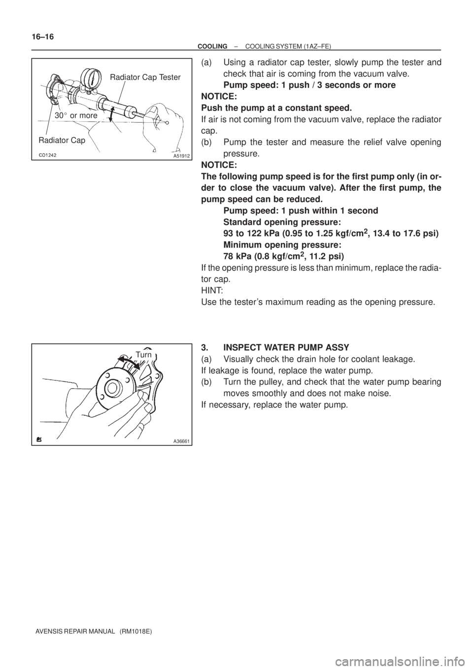
(a) Using a radiator cap tester, slowly pump the tester and
check that air is coming from the vacuum valve.
Pump speed: 1 push / 3 seconds or more
NOTICE:
Push the pump at a constant speed.
If air is not coming from the vacuum valve, replace the radiator
cap.
(b) Pump the tester and measure the relief valve opening
pressure.
NOTICE:
The following pump speed is for the first pump only (in or-
der to close the vacuum valve). After the first pump, the
pump speed can be reduced.
Pump speed: 1 push within 1 second
Standard opening pressure:
93 to 122 kPa (0.95 to 1.25 kgf/cm
2, 13.4 to 17.6 psi)
Minimum opening pressure:
78 kPa (0.8 kgf/cm
2, 11.2 psi)
If the opening pressure is less than minimum, replace the radia-
tor cap.
HINT:
Use the tester's maximum reading as the opening pressure.
3. INSPECT WATER PUMP ASSY
(a) Visually check the drain hole for coolant leakage.
If leakage is found, replace the water pump.
(b) Turn the pulley, and check that the water pump bearing
moves smoothly and does not make noise.
If necessary, replace the water pump.