Page 697 of 5135
A81008
ECM
E10 17
V±W
C11
Combination
Meter Assy
(RHD)
V±W
18
J20H
J/C
SP1
(RHD) J20
H
(LHD) J10
H
(LHD)J10
H
±
DIAGNOSTICS ECD SYSTEM(1CD±FTV)
05±641
AVENSIS REPAIR MANUAL (RM1018E)
WIRING DIAGRAM
INSPECTION PROCEDURE
HINT:
Read freeze frame data using �����\b��������
�� . Freeze frame data records the engine conditions when
a malfunction is detected. When troubleshooting, it is useful for determi\
ning whether the vehicle was running
or stopped, the engine was warmed up or not, etc. at the time of the malfu\
nction.
1CHECK OPERATION OF SPEEDOMETER
(a)Drive the vehicle and check if the operation of the speedometer in the combination meter is normal.
HINT:
The vehicle speed sensor is operating normally if the speedometer displa\
y is normal.
NGCHECK SPEEDOMETER CIRCUIT (See page 05±1510)
OK
Page 700 of 5135
A81510
Malfunction Detection
Actual Intake Shutter
Valve Opening Angle
ON
OFF Normal Abnormal
Fully Opened
Switch StatusOPEN CLOSE
Intake Shutter
Valve Control Motor
Step Counter
TimeAbnormal
Normal
OPEN CLOSE ECM Commanding Fully Open
05±634
± DIAGNOSTICSECD SYSTEM (1CD±FTV)
AVENSIS REPAIR MANUAL (RM1018E)
MONITOR DESCRIPTION
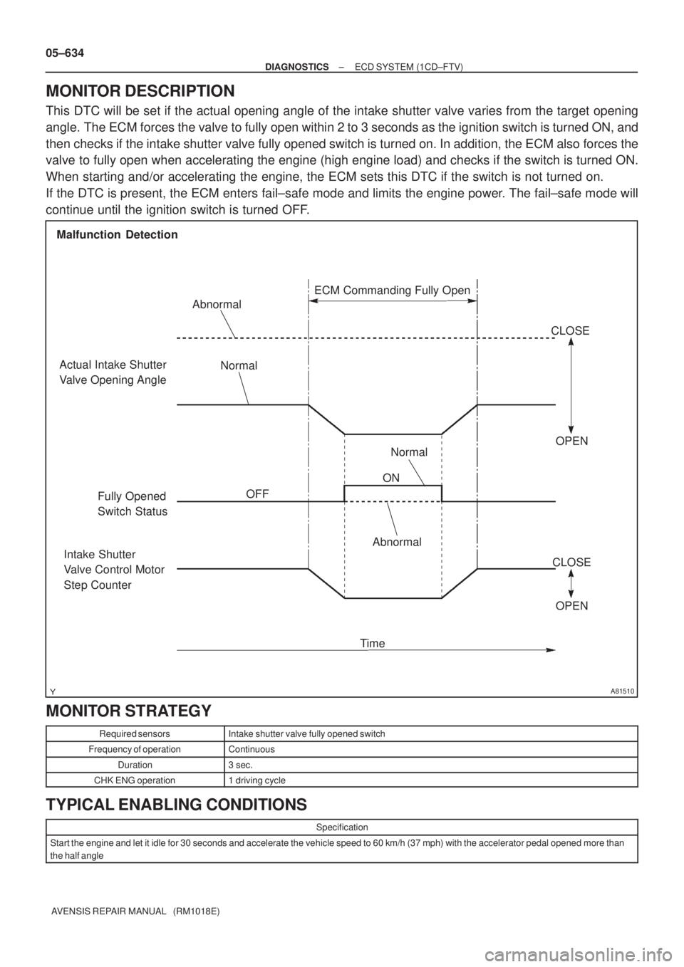
This DTC will be set if the actual opening angle of the intake shutter valve varies from the target opening
angle. The ECM forces the valve to fully open within 2 to 3 seconds as the ignition switch is turned ON, and
then checks if the intake shutter valve fully opened switch is turned on. In addition, the ECM also forces the
valve to fully open when accelerating the engine (high engine load) and checks if the switch is turned ON.
When starting and/or accelerating the engine, the ECM sets this DTC if the switch is not turned on.
If the DTC is present, the ECM enters fail±safe mode and limits the engine power. The fail±safe mode will
continue until the ignition switch is turned OFF.
MONITOR STRATEGY
Required sensorsIntake shutter valve fully opened switch
Frequency of operationContinuous
Duration3 sec.
CHK ENG operation1 driving cycle
TYPICAL ENABLING CONDITIONS
Specification
Start the engine and let it idle for 30 seconds and accelerate the vehicle speed to 60 km/h (37 mph) with the accelerator pedal opened more than
the half angle
Page 711 of 5135
± DIAGNOSTICSECD SYSTEM (1CD±FTV)
05±623
AVENSIS REPAIR MANUAL (RM1018E)DTC No.
DTC Detection ConditionTrouble Area
P0380
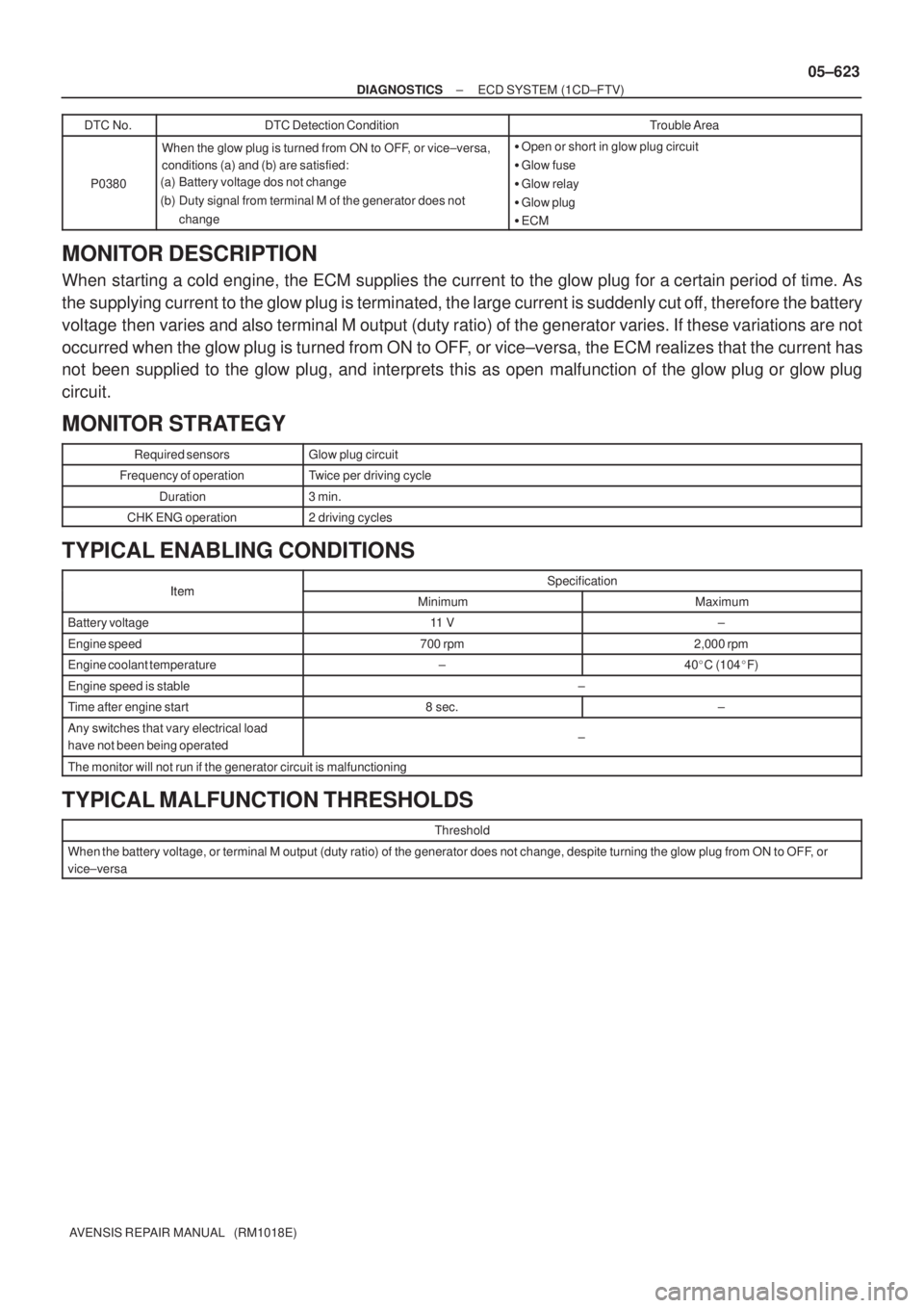
When the glow plug is turned from ON to OFF, or vice±versa,
conditions (a) and (b) are satisfied:
(a) Battery voltage dos not change
(b) Duty signal from terminal M of the generator does not
change�Open or short in glow plug circuit
�Glow fuse
�Glow relay
�Glow plug
�ECM
MONITOR DESCRIPTION
When starting a cold engine, the ECM supplies the current to the glow plug for a certain period of time. As
the supplying current to the glow plug is terminated, the large current is suddenly cut off, therefore the battery
voltage then varies and also terminal M output (duty ratio) of the generator varies. If these variations are not
occurred when the glow plug is turned from ON to OFF, or vice±versa, the ECM realizes that the current has
not been supplied to the glow plug, and interprets this as open malfunction of the glow plug or glow plug
circuit.
MONITOR STRATEGY
Required sensorsGlow plug circuit
Frequency of operationTwice per driving cycle
Duration3 min.
CHK ENG operation2 driving cycles
TYPICAL ENABLING CONDITIONS
ItemSpecificationItemMinimumMaximum
Battery voltage11 V±
Engine speed700 rpm2,000 rpm
Engine coolant temperature±40�C (104�F)
Engine speed is stable±
Time after engine start8 sec.±
Any switches that vary electrical load
have not been being operated±
The monitor will not run if the generator circuit is malfunctioning
TYPICAL MALFUNCTION THRESHOLDS
Threshold
When the battery voltage, or terminal M output (duty ratio) of the generator does not change, despite turning the glow plug from ON to OFF, or
vice±versa
Page 717 of 5135

A81512
G and NE Signal Waveforms5 V/
Division
G 20 msec./Division (Idling)
NE
A64984
Camshaft Position Sensor
05±620
±
DIAGNOSTICS ECD SYSTEM(1CD±FTV)
AVENSIS REPAIR MANUAL (RM1018E)
DTCP0340CAMSHAFT POSITION SENSOR ºAº CIRCUIT (BANK 1 OR SINGLE SENSOR)
CIRCUIT DESCRIPTION
Camshaft position sensor (G signal) consists of a magnet, iron core and pickup\
coil.
The G signal plate has one tooth on its outer circumference and is installe\
d on the camshaft timing pulley.
When the camshafts rotate, the protrusion on the signal plate and the air ga\
p on the pickup coil change,
causing fluctuations in the magnetic field and generating an electromoti\
ve force in the pickup coil.
The NE signal plate has 34 teeth and is mounted on the crankshaft timing pu\
lley. The NE signal sensor gen-
erates 34 signals at every engine revolution. The ECM detects the standard crankshaft angl\
e based on the
G signal and the actual crankshaft angle and the engine speed by the NE s\
ignal.
DTC No.DTC Detection ConditionTrouble Area
P0340
�No camshaft position sensor signal to ECM during cranking
(2 trip detection logic)�Open or short in camshaft position sensor circuit
� Camshaft position sensor
P0340(g)
�No camshaft position sensor signal to ECM with engine
speed 650 rpm or more (1 trip detection logic)�Camshaft timing pulley
� ECM
Reference: Inspection using the oscilloscope.
The correct waveform is as shown in the diagram on the left.
Symbols (Terminal No.)Specified condition
G1 (E12±23) ± G± (E12±31)Correct waveform is as shown
WIRING DIAGRAM
Refer to DTC P0335 on page 05±616.
INSPECTION PROCEDURE
HINT:
Read freeze frame data using �����\b��������
�� . Freeze frame data records the engine conditions when
a malfunction is detected. When troubleshooting, it is useful for determi\
ning whether the vehicle was running
or stopped, the engine was warmed up or not, etc. at the time of the malfu\
nction.
1INSPECT CAMSHAFT POSITION SENSOR
(a)Measure the resistance between terminals 1 and 2. Resistance:
1,630 to 2,740 � at cold
2,065 to 3,225 � at hot
NOTICE:
ºColdº and ºHotº shown above mean the temperature of
the coils themselves. ºColdº is from ±10 �C (14 �F) to 50 �C
(122 �F) and ºHotº is from 50 �C (122 �F) to 100 �C (212 �F).
NGREPLACE CAMSHAFT POSITION SENSOR (See page 10±63)
OK
05B5J±03
Page 718 of 5135
A54385
Wire Harness SideCamshaft Position Sensor Connector C1
A81087
E12
ECM Connector
G±
G1
±
DIAGNOSTICS ECD SYSTEM(1CD±FTV)
05±621
AVENSIS REPAIR MANUAL (RM1018E)
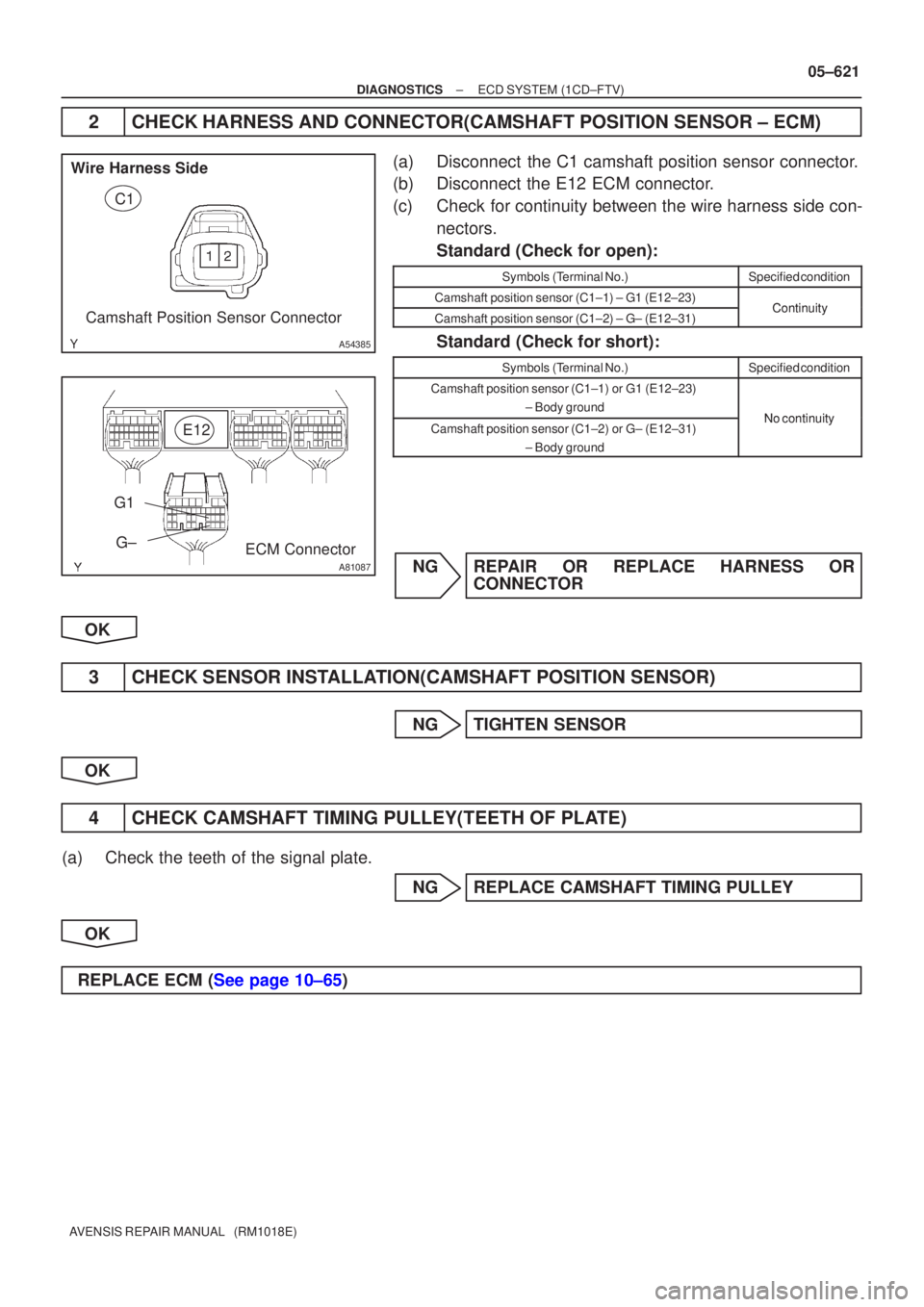
2CHECK HARNESS AND CONNECTOR(CAMSHAFT POSITION SENSOR ± ECM)
(a)Disconnect the C1 camshaft position sensor connector.
(b)Disconnect the E12 ECM connector.
(c)Check for continuity between the wire harness side con-
nectors.
Standard (Check for open):
Symbols (Terminal No.)Specified condition
Camshaft position sensor (C1±1) ± G1 (E12±23)ContinuityCamshaft position sensor (C1±2) ± G± (E12±31)Continuity
Standard (Check for short):
Symbols (Terminal No.)Specified condition
Camshaft position sensor (C1±1)or G1 (E12±23)
± Body ground
NocontinuityCamshaft position sensor (C1±2)or G± (E12±31) ± Body groundNo continuity
NGREPAIR OR REPLACE HARNESS ORCONNECTOR
OK
3CHECK SENSOR INSTALLATION(CAMSHAFT POSITION SENSOR)
NGTIGHTEN SENSOR
OK
4CHECK CAMSHAFT TIMING PULLEY(TEETH OF PLATE)
(a)Check the teeth of the signal plate. NGREPLACE CAMSHAFT TIMING PULLEY
OK
REPLACE ECM (See page 10±65)
Page 719 of 5135
A81512
G and NE Signal Waveforms
5 V/
Division
G
20 msec./Division (Idling) NE 05±616
± DIAGNOSTICSECD SYSTEM (1CD±FTV)
AVENSIS REPAIR MANUAL (RM1018E)
DTC P0335 CRANKSHAFT POSITION SENSOR ºAº
CIRCUIT
DTC P0339 CRANKSHAFT POSITION SENSOR ºAº
CIRCUIT INTERMITTENT
CIRCUIT DESCRIPTION
Crankshaft position sensor (NE signal) consists of a magnet, iron core and pickup coil.
The NE signal plate has 34 teeth and is installed the crankshaft timing pulley. The NE signal sensor gener-
ates 34 signals of every engine revolution. The ECM detects the standard crankshaft angle based on the
G signal, and the actual crankshaft angle and the engine speed by the NE signal.
DTC No.DTC Detection ConditionTrouble Area
P0335
No crankshaft position sensor signal to ECM during cranking
(2 trip detection logic)
P0335No crankshaft position sensor signal to ECM with engine
speed 650 rpm or more (2 trip detection logic)
�Open or short in crankshaftposition sensor circuit
P0339
In conditions (a), (b) and (c), when no crankshaft position sen-
sor (NE) signal is input for 0.05 sec. or more.
(1 trip detection logic)
(a) Engine revolution 1,000 rpm or more
(b) STA signal is OFF
(c) 3 sec. or more has lapsed after STA signal is switched from
ON to OFF.�Open or short in crankshaft position sensor circuit
�Crankshaft position sensor
�Signal plate (crankshaft timing pulley)
�ECM
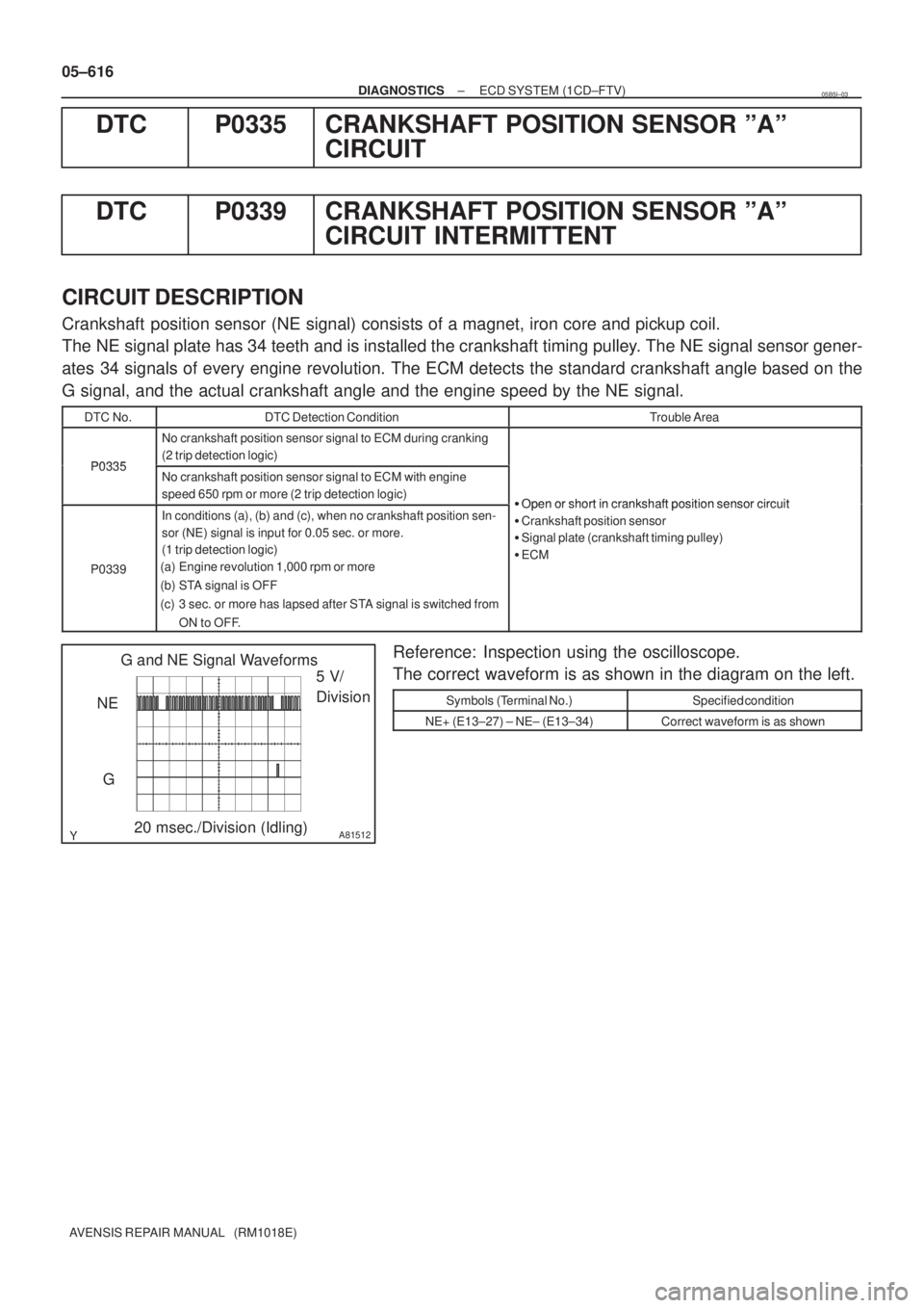
Reference: Inspection using the oscilloscope.
The correct waveform is as shown in the diagram on the left.
Symbols (Terminal No.)Specified condition
NE+ (E13±27) ± NE± (E13±34)Correct waveform is as shown
05B5I±03
Page 720 of 5135
A81004
ECM
C1
Camshaft Position Sensor
NE± NE+ G1
2723
E12
L P
E13
R
BR
EI C6
Crankshaft Position Sensor1
2
1
234
E1331
E12G±
G (Shielded)(Shielded)
EE
E
J12
J/CE1
± DIAGNOSTICSECD SYSTEM (1CD±FTV)
05±617
AVENSIS REPAIR MANUAL (RM1018E)
WIRING DIAGRAM
INSPECTION PROCEDURE
HINT:
�Perform troubleshooting of DTC P0335 first. If no trouble is found, troubleshoot the engine mechanical
systems.
�Read freeze frame data using ��� ��������� ��
�� . Freeze frame data records the engine conditions
when a malfunction is detected. When troubleshooting, it is useful for determining whether the vehicle
was running or stopped, the engine was warmed up or not, etc. at the time of the malfunction.
Page 721 of 5135
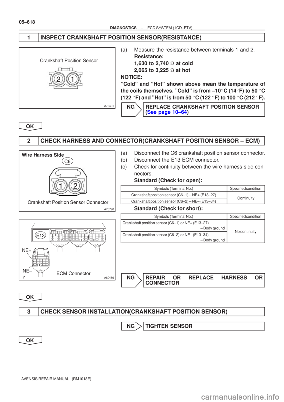
A78431
Crankshaft Position Sensor
A76790
Wire Harness SideCrankshaft Position Sensor Connector C6
A80459ECM Connector
NE+
NE± E13
05±618
±
DIAGNOSTICS ECD SYSTEM(1CD±FTV)
AVENSIS REPAIR MANUAL (RM1018E)
1INSPECT CRANKSHAFT POSITION SENSOR(RESISTANCE)
(a)Measure the resistance between terminals 1 and 2. Resistance:
1,630 to 2,740 � at cold
2,065 to 3,225 � at hot
NOTICE:
ºColdº and ºHotº shown above mean the temperature of
the coils themselves. ºColdº is from ±10 �C (14 �F) to 50 �C
(122 �F) and ºHotº is from 50 �C (122 �F) to 100 �C (212 �F).
NGREPLACE CRANKSHAFT POSITION SENSOR (See page 10±64)
OK
2 CHECK HARNESS AND CONNECTOR(CRANKSHAFT POSITION SENSOR ± ECM)
(a) Disconnect the C6 crankshaft position sensor connector.
(b) Disconnect the E13 ECM connector.
(c) Check for continuity between the wire harness side con- nectors.
Standard (Check for open):
Symbols (Terminal No.)Specified condition
Crankshaft position sensor (C6±1) ± NE+ (E13±27)ContinuityCrankshaft position sensor (C6±2) ± NE± (E13±34)Continuity
Standard (Check for short):
Symbols (Terminal No.)Specified condition
Crankshaft position sensor (C6±1) or NE+ (E13±27)
± Body ground
No continuityCrankshaft position sensor (C6±2) or NE± (E13±34) ± Body groundNo continuity
NG REPAIR OR REPLACE HARNESS ORCONNECTOR
OK
3 CHECK SENSOR INSTALLATION(CRANKSHAFT POSITION SENSOR)
NG TIGHTEN SENSOR
OK