Page 722 of 5135
±
DIAGNOSTICS ECD SYSTEM(1CD±FTV)
05±619
AVENSIS REPAIR MANUAL (RM1018E)
4CHECK CRANKSHAFT POSITION SENSOR PLATE(TEETH OF SENSOR
PLATE(CRANKSHAFT TIMING PULLEY))
(a)Check the teeth of the sensor plate.
NGREPLACE CRANKSHAFT POSITION SENSORPLATE (CAMSHAFT TIMING PULLEY)
OK
REPLACE ECM (See page 10±65)
Page 728 of 5135
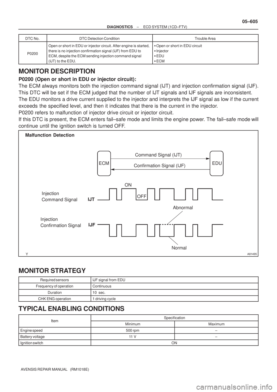
A81495
Malfunction Detection
ECMCommand Signal (IJT)
EDU
Confirmation Signal (IJF)
Injection
Command Signal
Injection
Confirmation SignalIJFON
OFF
NormalAbnormal
IJT
± DIAGNOSTICSECD SYSTEM (1CD±FTV)
05±605
AVENSIS REPAIR MANUAL (RM1018E)DTC No.
DTC Detection ConditionTrouble Area
P0200
Open or short in EDU or injector circuit. After engine is started,
there is no injection confirmation signal (IJF) from EDU to
ECM, despite the ECM sending injection command signal
(IJT) to the EDU.�Open or short in EDU circuit
�Injector
�EDU
�ECM
MONITOR DESCRIPTION
P0200 (Open or short in EDU or injector circuit):
The ECM always monitors both the injection command signal (IJT) and injection confirmation signal (IJF).
This DTC will be set if the ECM judged that the number of IJT signals and IJF signals are inconsistent.
The EDU monitors a drive current supplied to the injector and interprets the IJF signal as low if the current
exceeds the specified level, and then it indicates that there is the current in the injector.
P0200 refers to malfunction of injector drive circuit or injector circuit.
If this DTC is present, the ECM enters fail±safe mode and limits the engine power. The fail±safe mode will
continue until the ignition switch is turned OFF.
MONITOR STRATEGY
Required sensorsIJF signal from EDU
Frequency of operationContinuous
Duration10 sec.
CHK ENG operation1 driving cycle
TYPICAL ENABLING CONDITIONS
ItemSpecificationItemMinimumMaximum
Engine speed500 rpm±
Battery voltage11 V±
Ignition switchON
Page 735 of 5135

±
DIAGNOSTICS ECD SYSTEM(1CD±FTV)
05±603
AVENSIS REPAIR MANUAL (RM1018E)
DTCP0191FUEL RAIL PRESSURE SENSOR CIRCUIT
RANGE/PERFORMANCE
CIRCUIT DESCRIPTION
Refer to DTCs P0087 on page 05±557.
INSPECTION PROCEDURE
HINT:
�If DTCs ºP0087, P0190, P0192,and P0193º are output simultaneously, manifold absolute pressure
sensor circuit may be open or short. Perform the troubleshooting of DTC ºP0087, P0190, P019\
2,and
P0193º first.
�Read freeze frame data using the hand±held tester. Freeze frame data records the engine conditions
when a malfunction is detected. When troubleshooting, it is useful for deter\
mining whether the vehicle
was running or stopped, the engine was warmed up or not, etc. at the time o\
f the malfunction.
DTC No.DTC Detection ConditionTrouble Area
P0191Voltage output of the fuel pressure sensor for the common rail
is out of the standard range. (1 trip detection logic)�Fuel pressure sensor
1CHECK OTHER DTC OUTPUT(BESIDS DTC P0191)
(a)Read the DTC using the hand±held tester.
Result:
Display (DTC output)Proceed to
Only P0191 is outputA
P0191 and other DTCs are outputB
HINT:
If any other codes besides P0191 are output, perform the troubleshoot for \
those DTCs first.
BGO TO RELEVANT DTC CHART(See page 05±544)
A
REPLACE COMMON RAIL ASSY (FUEL PRESSURE SENSOR) (See page 11±78)
05CPQ±01
Page 736 of 5135
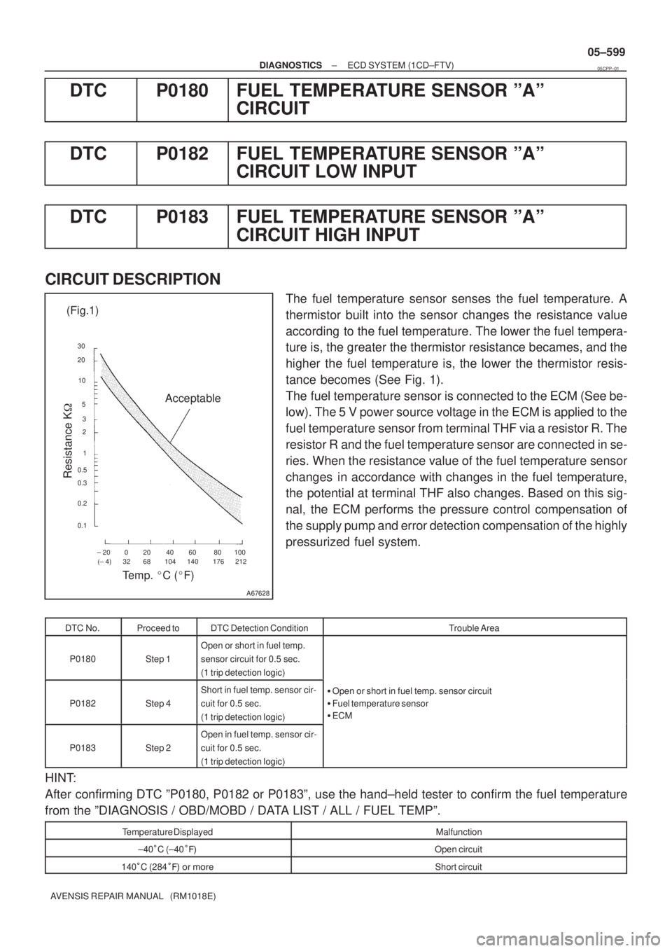
± 20 0 20 40 60 80 100
(± 4) 32 68 104 140 176 212 30
20
10
5
3
2
1
0.5
0.3
0.2
0.1
A67628
Acceptable (Fig.1)
Resistance K�
Temp. �C (�F)
± DIAGNOSTICSECD SYSTEM (1CD±FTV)
05±599
AVENSIS REPAIR MANUAL (RM1018E)
DTC P0180 FUEL TEMPERATURE SENSOR ºAº
CIRCUIT
DTC P0182 FUEL TEMPERATURE SENSOR ºAº
CIRCUIT LOW INPUT
DTC P0183 FUEL TEMPERATURE SENSOR ºAº
CIRCUIT HIGH INPUT
CIRCUIT DESCRIPTION
The fuel temperature sensor senses the fuel temperature. A
thermistor built into the sensor changes the resistance value
according to the fuel temperature. The lower the fuel tempera-
ture is, the greater the thermistor resistance becames, and the
higher the fuel temperature is, the lower the thermistor resis-
tance becomes (See Fig. 1).
The fuel temperature sensor is connected to the ECM (See be-
low). The 5 V power source voltage in the ECM is applied to the
fuel temperature sensor from terminal THF via a resistor R. The
resistor R and the fuel temperature sensor are connected in se-
ries. When the resistance value of the fuel temperature sensor
changes in accordance with changes in the fuel temperature,
the potential at terminal THF also changes. Based on this sig-
nal, the ECM performs the pressure control compensation of
the supply pump and error detection compensation of the highly
pressurized fuel system.
DTC No.Proceed toDTC Detection ConditionTrouble Area
P0180Step 1
Open or short in fuel temp.
sensor circuit for 0.5 sec.
(1 trip detection logic)
P0182Step 4
Short in fuel temp. sensor cir-
cuit for 0.5 sec.
(1 trip detection logic)�Open or short in fuel temp. sensor circuit
�Fuel temperature sensor
�ECM
P0183Step 2
Open in fuel temp. sensor cir-
cuit for 0.5 sec.
(1 trip detection logic)
HINT:
After confirming DTC ºP0180, P0182 or P0183º, use the hand±held tester to confirm the fuel temperature
from the ºDIAGNOSIS / OBD/MOBD / DATA LIST / ALL / FUEL TEMPº.
Temperature DisplayedMalfunction
±40�C (±40���Open circuit
140�C (284��� �� ����Short circuit
05CPP±01
Page 737 of 5135
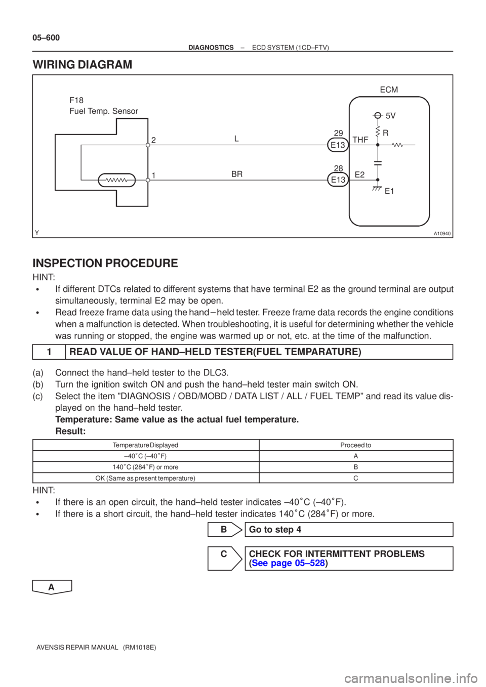
A10940
ECM
THF E2
F18
Fuel Temp. Sensor
1
2
5V
R
E1
E13
E13 28 29
L
BR
05±600
±
DIAGNOSTICS ECD SYSTEM(1CD±FTV)
AVENSIS REPAIR MANUAL (RM1018E)
WIRING DIAGRAM
INSPECTION PROCEDURE
HINT:
�If different DTCs related to different systems that have terminal E2 as the ground terminal are output
simultaneously, terminal E2 may be open.
�Read freeze frame data using
\b�\b�
��\b� �
�\f
��� Freeze frame data records the engine conditions
when a malfunction is detected. When troubleshooting, it is useful for d\
etermining whether the vehicle
was running or stopped, the engine was warmed up or not, etc. at the time o\
f the malfunction.
1READ VALUE OF HAND±HELD TESTER(FUEL TEMPARATURE)
(a)Connect the hand±held tester to the DLC3.
(b)Turn the ignition switch ON and push the hand±held tester main switch \
ON.
(c)Select the item ºDIAGNOSIS / OBD/MOBD / DATA LIST / ALL / FUEL TEMPº and read its value dis- played on the hand±held tester.
Temperature: Same value as the actual fuel temperature.
Result:
Temperature DisplayedProceed to
±40�C (±40 ��)A
140 �C (284 ��) or moreB
OK (Same as present temperature)C
HINT:
�If there is an open circuit, the hand±held tester indicates ±40 �C (±40 �F).
�If there is a short circuit, the hand±held tester indicates 140 �C (284 �F) or more.
BGo to step 4
CCHECK FOR INTERMITTENT PROBLEMS (See page 05±528)
A
Page 738 of 5135
A75743
Fuel Temp. SensorECM
A66104
F18
Wire Harness SideFuel Temp. Sensor Connector
A75742
Fuel Temp. SensorECM
A80450
THFE2
E13
ECM Connector
±
DIAGNOSTICS ECD SYSTEM(1CD±FTV)
05±601
AVENSIS REPAIR MANUAL (RM1018E)
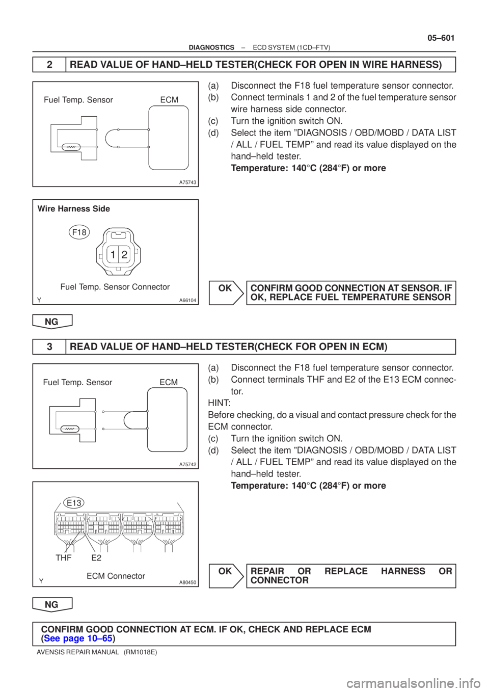
2READ VALUE OF HAND±HELD TESTER(CHECK FOR OPEN IN WIRE HARNESS)
(a)Disconnect the F18 fuel temperature sensor connector.
(b)Connect terminals 1 and 2 of the fuel temperature sensor
wire harness side connector.
(c)Turn the ignition switch ON.
(d)Select the item ºDIAGNOSIS / OBD/MOBD / DATA LIST / ALL / FUEL TEMPº and read its value displayed on the
hand±held tester.
Temperature: 140 �C (284 �F) or more
OKCONFIRM GOOD CONNECTION AT SENSOR. IF OK, REPLACE FUEL TEMPERATURE SENSOR
NG
3READ VALUE OF HAND±HELD TESTER(CHECK FOR OPEN IN ECM)
(a)Disconnect the F18 fuel temperature sensor connector.
(b)Connect terminals THF and E2 of the E13 ECM connec- tor.
HINT:
Before checking, do a visual and contact pressure check for the
ECM connector.
(c)Turn the ignition switch ON.
(d)Select the item ºDIAGNOSIS / OBD/MOBD / DATA LIST / ALL / FUEL TEMPº and read its value displayed on the
hand±held tester.
Temperature: 140 �C (284 �F) or more
OKREPAIR OR REPLACE HARNESS OR CONNECTOR
NG
CONFIRM GOOD CONNECTION AT ECM. IF OK, CHECK AND REPLACE ECM
(See page 10±65)
Page 739 of 5135
A76591
Fuel Temp. SensorECM
A75744
Fuel Temp. SensorECM
A80456
E13
ECM ConnectorTHF
05±602
±
DIAGNOSTICS ECD SYSTEM(1CD±FTV)
AVENSIS REPAIR MANUAL (RM1018E)
4READ VALUE OF HAND±HELD TESTER(CHECK FOR SHORT IN WIRE HARNESS)
(a)Disconnect the F18 fuel temperature sensor connector.
(b)Turn the ignition switch ON.
(c)Select the item ºDIAGNOSIS / OBD/MOBD / DATA LIST / ALL / FUEL TEMPº and read its value displayed on the
hand±held tester.
Temperature: ±40 �C (±40 �F)
OKREPLACE FUEL TEMPERATURE SENSOR
NG
5READ VALUE OF HAND±HELD TESTER(CHECK FOR SHORT IN ECM)
(a)Disconnect the E13 ECM connector.
(b)Turn the ignition switch ON.
(c)Select the item ºDIAGNOSIS / OBD/MOBD / DATA LIST / ALL / FUEL TEMPº and read its value displayed on the
hand±held tester.
Temperature: ±40 �C (±40 �F)
OKREPAIR OR REPLACE HARNESS OR CONNECTOR
NG
REPLACE ECM (See page 10±65)
Page 747 of 5135
±
DIAGNOSTICS ECD SYSTEM(1CD±FTV)
05±685
AVENSIS REPAIR MANUAL (RM1018E)
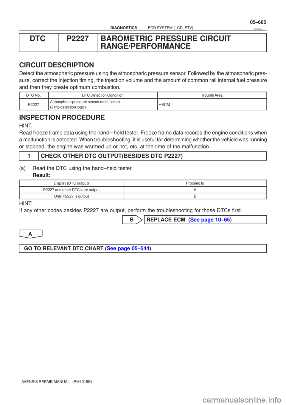
DTCP2227BAROMETRIC PRESSURE CIRCUIT
RANGE/PERFORMANCE
CIRCUIT DESCRIPTION
Detect the atmospheric pressure using the atmospheric pressure sensor. Followed by the atmospheric pres-
sure, correct the injection timing, the injection volume and the amount of co\
mmon rail internal fuel pressure
and then they create optimum combustion.
DTC No.DTC Detection ConditionTrouble Area
P2227Atmospheric pressure sensor malfunction
(2 trip detection logic)�ECM
INSPECTION PROCEDURE
HINT:
Read freeze frame data using �����\b��������
�� . Freeze frame data records the engine conditions when
a malfunction is detected. When troubleshooting, it is useful for determi\
ning whether the vehicle was running
or stopped, the engine was warmed up or not, etc. at the time of the malfu\
nction.
1CHECK OTHER DTC OUTPUT(BESIDES DTC P2227)
(a)Read the DTC using the hand±held tester. Result:
Display (DTC output)Proceed to
P2227 and other DTCs are outputA
Only P2227 is outputB
HINT:
If any other codes besides P2227 are output, perform the troubleshooting f\
or those DTCs first.
BREPLACE ECM (See page 10±65)
A
GO TO RELEVANT DTC CHART (See page 05±544)
05CQ6±01