Page 667 of 5135
A81002
5V
W±R E13
3
2
1
VC
PIM
E2
T5
Manifold Absolute
Pressure Sensor
ECM
E2
PIM
VC
28 28 18
R±W
BR E12
E13
±
DIAGNOSTICS ECD SYSTEM(1CD±FTV)
05±585
AVENSIS REPAIR MANUAL (RM1018E)
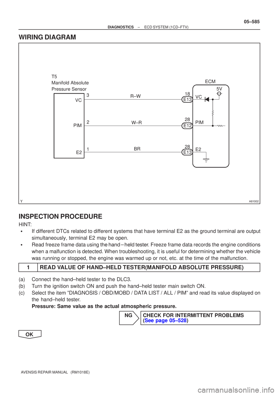
WIRING DIAGRAM
INSPECTION PROCEDURE
HINT:
�If different DTCs related to different systems that have terminal E2 as the ground terminal are output
simultaneously, terminal E2 may be open.
�Read freeze frame data using \f���� ����\b�\f��\f�
� Freeze frame data records the engine conditions
when a malfunction is detected. When troubleshooting, it is useful for d\
etermining whether the vehicle
was running or stopped, the engine was warmed up or not, etc. at the time o\
f the malfunction.
1READ VALUE OF HAND±HELD TESTER(MANIFOLD ABSOLUTE PRESSURE)
(a)Connect the hand±held tester to the DLC3.
(b)Turn the ignition switch ON and push the hand±held tester main switch \
ON.
(c)Select the item ºDIAGNOSIS / OBD/MOBD / DATA LIST / ALL / PIMº and read its value displayed on the hand±held tester.
Pressure: Same value as the actual atmospheric pressure.
NGCHECK FOR INTERMITTENT PROBLEMS(See page 05±528)
OK
Page 669 of 5135
A56992
E2
PIM
VC
T5
Wire Harness Side
Manifold Absolute
Pressure Sensor Connector
A81088
PIM
VC
E2E12ECM Connector
E13
±
DIAGNOSTICS ECD SYSTEM(1CD±FTV)
05±587
AVENSIS REPAIR MANUAL (RM1018E)
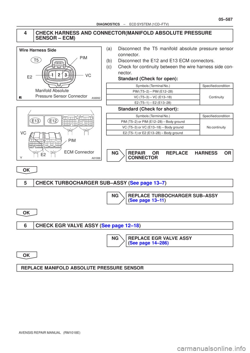
4CHECK HARNESS AND CONNECTOR(MANIFOLD ABSOLUTE PRESSURE
SENSOR ± ECM)
(a)Disconnect the T5 manifold absolute pressure sensor
connector.
(b)Disconnect the E12 and E13 ECM connectors.
(c)Check for continuity between the wire harness side con- nector.
Standard (Check for open):
Symbols (Terminal No.)Specified condition
PIM (T5±2) ± PIM (E12±28)
VC (T5±3) ± VC (E13±18)Continuity
E2 (T5±1) ± E2 (E13±28)
y
Standard (Check for short):
Symbols (Terminal No.)Specified condition
PIM (T5±2) or PIM (E12±28) ± Body ground
VC (T5±3) or VC (E13±18) ± Body groundNo continuity
E2 (T5±1) or E2 (E13±28) ± Body ground
y
NGREPAIR OR REPLACE HARNESS OR CONNECTOR
OK
5CHECK TURBOCHARGER SUB±ASSY (See page 13±7)
NG REPLACE TURBOCHARGER SUB±ASSY (See page 13±11)
OK
6CHECK EGR VALVE ASSY (See page 12±18)
NG REPLACE EGR VALVE ASSY (See page 14±286)
OK
REPLACE MANIFOLD ABSOLUTE PRESSURE SENSOR
Page 670 of 5135
� ����������
AB B+
Power Transistor
Platinum Hot Wire
(Heater)
Output
Voltage
Temperature
sensor
Platinum Hot Wire (Heater)
Temperature sensor
A53295
± DIAGNOSTICSECD SYSTEM (1CD±FTV)
05±577
AVENSIS REPAIR MANUAL (RM1018E)
DTC P0100 MASS OR VOLUME AIR FLOW CIRCUIT
DTC P0102 MASS OR VOLUME AIR FLOW CIRCUIT
LOW INPUT
DTC P0103 MASS OR VOLUME AIR FLOW CIRCUIT
HIGH INPUT
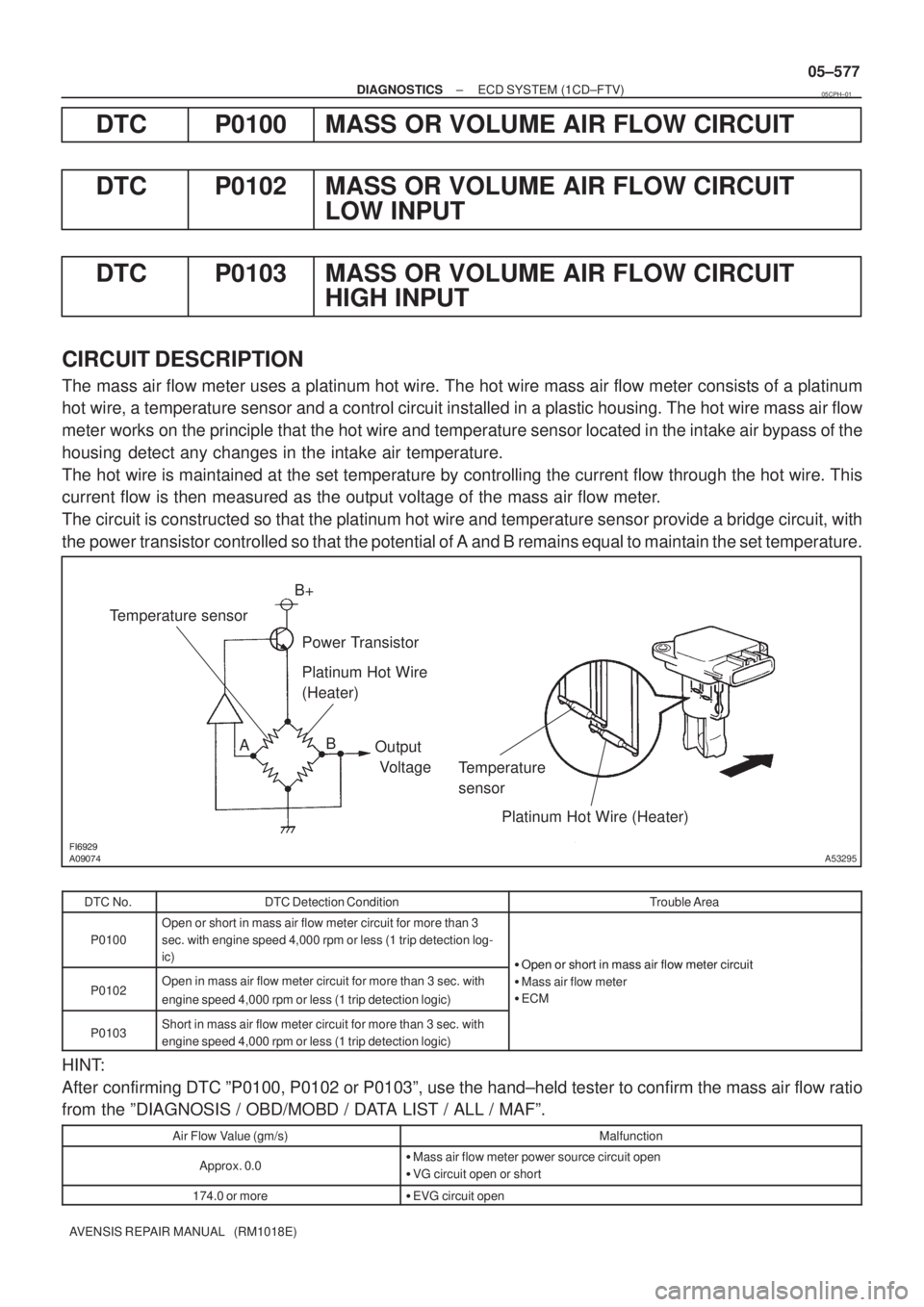
CIRCUIT DESCRIPTION
The mass air flow meter uses a platinum hot wire. The hot wire mass air flow meter consists of a platinum
hot wire, a temperature sensor and a control circuit installed in a plastic housing. The hot wire mass air flow
meter works on the principle that the hot wire and temperature sensor located in the intake air bypass of the
housing detect any changes in the intake air temperature.
The hot wire is maintained at the set temperature by controlling the current flow through the hot wire. This
current flow is then measured as the output voltage of the mass air flow meter.
The circuit is constructed so that the platinum hot wire and temperature sensor provide a bridge circuit, with
the power transistor controlled so that the potential of A and B remains equal to maintain the set temperature.
DTC No.DTC Detection ConditionTrouble Area
P0100
Open or short in mass air flow meter circuit for more than 3
sec. with engine speed 4,000 rpm or less (1 trip detection log-
ic)
�Open or short in mass air flow meter circuit
P0102Open in mass air flow meter circuit for more than 3 sec. with
engine speed 4,000 rpm or less (1 trip detection logic)
�Open or short in mass air flow meter circuit
�Mass air flow meter
�ECM
P0103Short in mass air flow meter circuit for more than 3 sec. with
engine speed 4,000 rpm or less (1 trip detection logic)
HINT:
After confirming DTC ºP0100, P0102 or P0103º, use the hand±held tester to confirm the mass air flow ratio
from the ºDIAGNOSIS / OBD/MOBD / DATA LIST / ALL / MAFº.
Air Flow Value (gm/s)Malfunction
Approx. 0.0�Mass air flow meter power source circuit open
�VG circuit open or short
174.0 or more�EVG circuit open
05CPH±01
Page 674 of 5135
A54396
+B (+)
Wire Harness Side
Mass Air Flow Meter ConnectorA6
A66056
Engine Room R/B No. 1
EFI Main Relay
A66060
EVG
E12
ECM Connector
±
DIAGNOSTICS ECD SYSTEM(1CD±FTV)
05±581
AVENSIS REPAIR MANUAL (RM1018E)
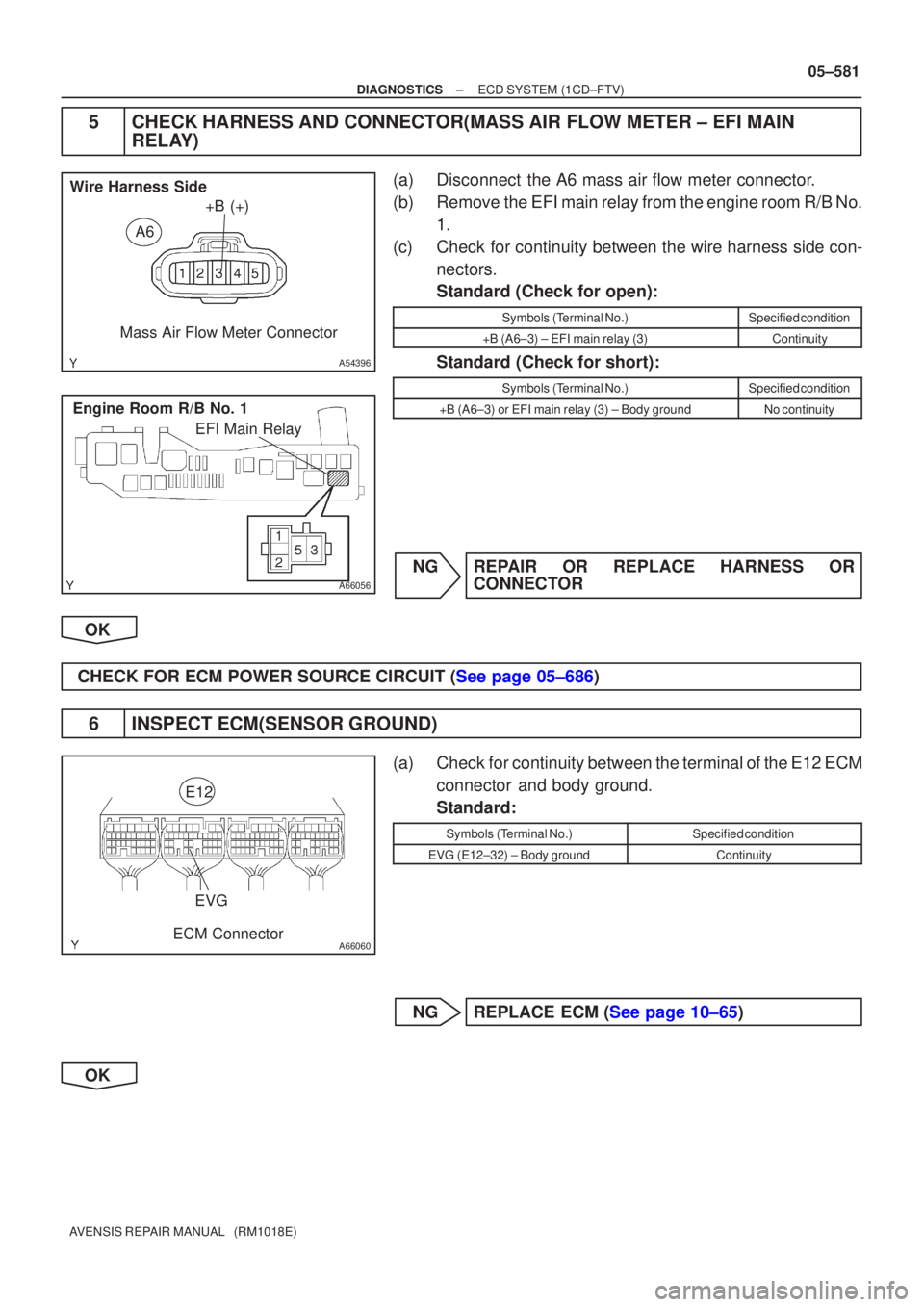
5CHECK HARNESS AND CONNECTOR(MASS AIR FLOW METER ± EFI MAIN
RELAY)
(a)Disconnect the A6 mass air flow meter connector.
(b)Remove the EFI main relay from the engine room R/B No.
1.
(c)Check for continuity between the wire harness side con- nectors.
Standard (Check for open):
Symbols (Terminal No.)Specified condition
+B (A6±3) ± EFI main relay (3)Continuity
Standard (Check for short):
Symbols (Terminal No.)Specified condition
+B (A6±3) or EFI main relay (3) ± Body groundNo continuity
NGREPAIR OR REPLACE HARNESS OR CONNECTOR
OK
CHECK FOR ECM POWER SOURCE CIRCUIT (See page 05±686)
6INSPECT ECM(SENSOR GROUND)
(a)Check for continuity between the terminal of the E12 ECM connector and body ground.
Standard:
Symbols (Terminal No.)Specified condition
EVG (E12±32) ± Body groundContinuity
NGREPLACE ECM (See page 10±65)
OK
Page 676 of 5135
± 20 0 20 40 60 80 100
(± 4) 32 68 104 140 176 212 30
20
10
5
3
2
1
0.5
0.3
0.2
0.1
A56991
(Fig. 1)
Acceptable
Resistance k�
Temp.�C (�F)
± DIAGNOSTICSECD SYSTEM (1CD±FTV)
05±573
AVENSIS REPAIR MANUAL (RM1018E)
DTC P0095 INTAKE AIR TEMPERATURE SENSOR 2
CIRCUIT
DTC P0097 INTAKE AIR TEMPERATURE SENSOR 2
CIRCUIT LOW
DTC P0098 INTAKE AIR TEMPERATURE SENSOR 2
CIRCUIT HIGH
CIRCUIT DESCRIPTION
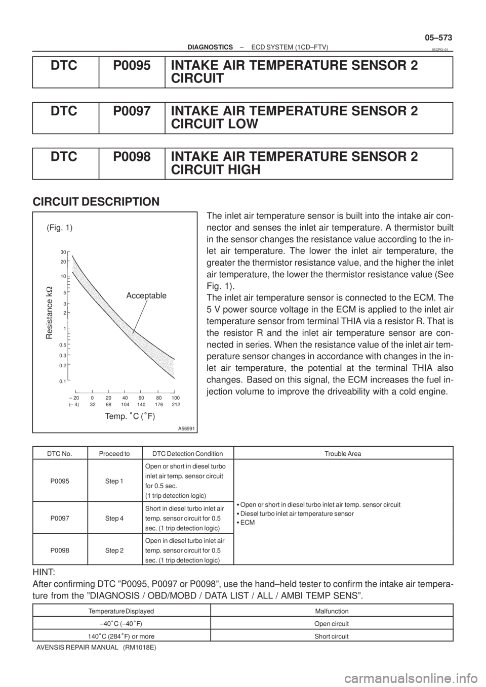
The inlet air temperature sensor is built into the intake air con-
nector and senses the inlet air temperature. A thermistor built
in the sensor changes the resistance value according to the in-
let air temperature. The lower the inlet air temperature, the
greater the thermistor resistance value, and the higher the inlet
air temperature, the lower the thermistor resistance value (See
Fig. 1).
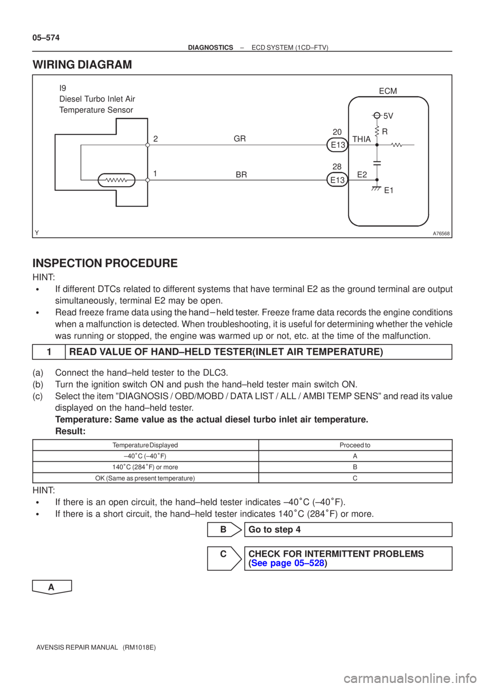
The inlet air temperature sensor is connected to the ECM. The
5 V power source voltage in the ECM is applied to the inlet air
temperature sensor from terminal THIA via a resistor R. That is
the resistor R and the inlet air temperature sensor are con-
nected in series. When the resistance value of the inlet air tem-
perature sensor changes in accordance with changes in the in-
let air temperature, the potential at the terminal THIA also
changes. Based on this signal, the ECM increases the fuel in-
jection volume to improve the driveability with a cold engine.
DTC No.Proceed toDTC Detection ConditionTrouble Area
P0095Step 1
Open or short in diesel turbo
inlet air temp. sensor circuit
for 0.5 sec.
(1 trip detection logic)
P0097Step 4
Short in diesel turbo inlet air
temp. sensor circuit for 0.5
sec. (1 trip detection logic)�Open or short in diesel turbo inlet air temp. sensor circuit
�Diesel turbo inlet air temperature sensor
�ECM
P0098Step 2
Open in diesel turbo inlet air
temp. sensor circuit for 0.5
sec. (1 trip detection logic)
HINT:
After confirming DTC ºP0095, P0097 or P0098º, use the hand±held tester to confirm the intake air tempera-
ture from the ºDIAGNOSIS / OBD/MOBD / DATA LIST / ALL / AMBI TEMP SENSº.
Temperature DisplayedMalfunction
±40�C (±40���Open circuit
140�C (284��� �� ����Short circuit
05CPG±01
Page 677 of 5135
A76568
I9
Diesel Turbo Inlet Air
Temperature Sensor2
1 GR
E2E1
THIA
R5V
ECM
E13 E13
20
28
BR
05±574
±
DIAGNOSTICS ECD SYSTEM(1CD±FTV)
AVENSIS REPAIR MANUAL (RM1018E)
WIRING DIAGRAM
INSPECTION PROCEDURE
HINT:
�If different DTCs related to different systems that have terminal E2 as the ground terminal are output
simultaneously, terminal E2 may be open.
�Read freeze frame data using
\b�\b�
��\b� �
�\f
��� Freeze frame data records the engine conditions
when a malfunction is detected. When troubleshooting, it is useful for d\
etermining whether the vehicle
was running or stopped, the engine was warmed up or not, etc. at the time o\
f the malfunction.
1READ VALUE OF HAND±HELD TESTER(INLET AIR TEMPERATURE)
(a)Connect the hand±held tester to the DLC3.
(b)Turn the ignition switch ON and push the hand±held tester main switch \
ON.
(c)Select the item ºDIAGNOSIS / OBD/MOBD / DATA LIST / ALL / AMBI TEMP SENSº and read its value displayed on the hand±held tester.
Temperature: Same value as the actual diesel turbo inlet air temperature.\
Result:
Temperature DisplayedProceed to
±40�C (±40 ��)A
140 �C (284 ��) or moreB
OK (Same as present temperature)C
HINT:
�If there is an open circuit, the hand±held tester indicates ±40 �C (±40 �F).
�If there is a short circuit, the hand±held tester indicates 140 �C (284 �F) or more.
BGo to step 4
CCHECK FOR INTERMITTENT PROBLEMS (See page 05±528)
A
Page 678 of 5135
A75743
Diesel Turbo Inlet Air
Temp. SensorECM
A56868
I9
Wire Harness Side
Diesel Turbo
Inlet Air Temp. Sensor Connector
THIA
E2
A75742
Diesel Turbo Inlet Air
Temp. Sensor
ECM
A80455
THIA
E2
E13
ECM Connector
±
DIAGNOSTICS ECD SYSTEM(1CD±FTV)
05±575
AVENSIS REPAIR MANUAL (RM1018E)
2READ VALUE OF HAND±HELD TESTER(CHECK FOR OPEN IN WIRE HARNESS)
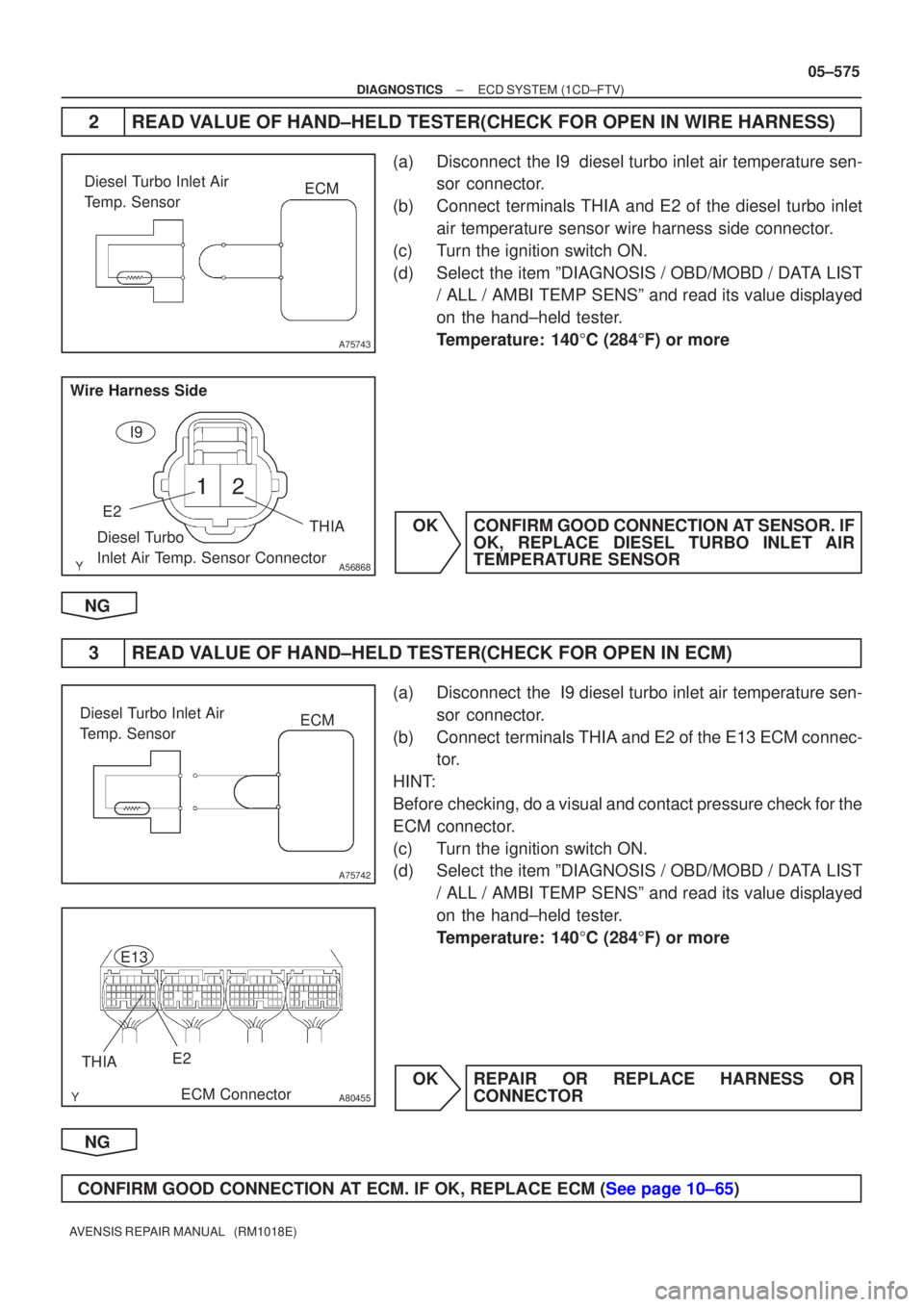
(a)Disconnect the I9 diesel turbo inlet air temperature sen-
sor connector.
(b)Connect terminals THIA and E2 of the diesel turbo inlet air temperature sensor wire harness side connector.
(c)Turn the ignition switch ON.
(d)Select the item ºDIAGNOSIS / OBD/MOBD / DATA LIST / ALL / AMBI TEMP SENSº and read its value displayed
on the hand±held tester.
Temperature: 140 �C (284 �F) or more
OKCONFIRM GOOD CONNECTION AT SENSOR. IF OK, REPLACE DIESEL TURBO INLET AIR
TEMPERATURE SENSOR
NG
3READ VALUE OF HAND±HELD TESTER(CHECK FOR OPEN IN ECM)
(a)Disconnect the I9 diesel turbo inlet air temperature sen- sor connector.
(b)Connect terminals THIA and E2 of the E13 ECM connec- tor.
HINT:
Before checking, do a visual and contact pressure check for the
ECM connector.
(c)Turn the ignition switch ON.
(d)Select the item ºDIAGNOSIS / OBD/MOBD / DATA LIST / ALL / AMBI TEMP SENSº and read its value displayed
on the hand±held tester.
Temperature: 140 �C (284 �F) or more
OKREPAIR OR REPLACE HARNESS OR CONNECTOR
NG
CONFIRM GOOD CONNECTION AT ECM. IF OK, REPLACE ECM (See page 10±65)
Page 679 of 5135
A76591
Diesel Turbo Inlet Air
Temp. SensorECM
A75744
Diesel Turbo Inlet Air
Temp. SensorECM
A80456
E13
ECM Connector
THIA
E2
05±576
±
DIAGNOSTICS ECD SYSTEM(1CD±FTV)
AVENSIS REPAIR MANUAL (RM1018E)
4READ VALUE OF HAND±HELD TESTER(CHECK FOR SHORT IN WIRE HARNESS)
(a)Disconnect the I9 diesel turbo inlet air temperature sensor connector.
(b)Turn the ignition switch ON.
(c)Select the item ºDIAGNOSIS / OBD/MOBD / DATA LIST / ALL / AMBI TEMP SENSº and read its value displayed
on the hand±held tester.
Temperature: ±40 �C (±40 �F)
OKREPLACE DIESEL TURBO INLET AIR TENPERATURE SENSOR
NG
5READ VALUE OF HAND±HELD TESTER(CHECK FOR SHORT IN ECM)
(a)Disconnect the E13 ECM connector.
(b)Turn the ignition switch ON.
(c)Select the item ºDIAGNOSIS / OBD/MOBD / DATA LIST / ALL / AMBI TEMP SENSº and read its value displayed
on the hand±held tester.
Temperature: ±40 �C (±40 �F)
OKREPAIR OR REPLACE HARNESS OR CONNECTOR
NG
REPLACE ECM (See page 10±65)