Page 3284 of 5135
720J5±01
B70315
Headrest Support
Power Seat Switch Assy
Power Seat Switch Knob Front Seat Inner Belt Assy LH
Front Seat Headrest Assy
� Hog Ring
Separate Type Front Seatback Cover
� Hog Ring
Front Seatback Pad
Seat Cushion Pad
Reclining Adjuster Inside Cover RH
Reclining Adjuster Inside Cover LH
Vertical Adjuster Bracket Cover Outer
Wire Harness Connector
Front Seat Cushion Shield LHHeadrest Support
Lumbar Support Adjuster Assy
Seat Track Cover
42 (428, 31)
6.0 (61, 53 in.�lbf)
: Specified torqueN�m (kgf�cm, ft�lbf)
� Non±reusable part
Front Power Seat Switch
37 (375, 27) Clip
Clip
8.0 (82, 71 in.�lbf)
Seat Position Airbag Sensor
Bush
37 (375, 27)37 (375, 27)
Front Seat Cushion Shield Front Seat Cushion Shield Inner LH
4.5 (46, 40 in.�lbf)
4.0 (41, 35 in.�lbf)
2.5 (25, 22 in.�lbf)
2.5 (25, 22 in.�lbf)
25 (255, 18)
3.5 (36, 31 in.�lbf)
25 (255, 18) Power Seat Motor Assy (Lifter)
(Front Vertical)Power Seat Motor Assy
(Reclining)Power Seat Motor Assy
Power Seat Motor AssyFront Seat Adjuster Assy LH Separate Type Front Seat Cushion Cover Separate Type Front
Vertical Adjuster
Inner No.1 LH
(w/ Seat Heater)
(w/ Seat Heater)
Seat Heater Control Sub±assy
Bracket Cover Inner
(Slide)
72±10
± SEATFRONT SEAT ASSEMBLY LH (POWER SEAT TYPE)
AVENSIS REPAIR MANUAL (RM1018E)
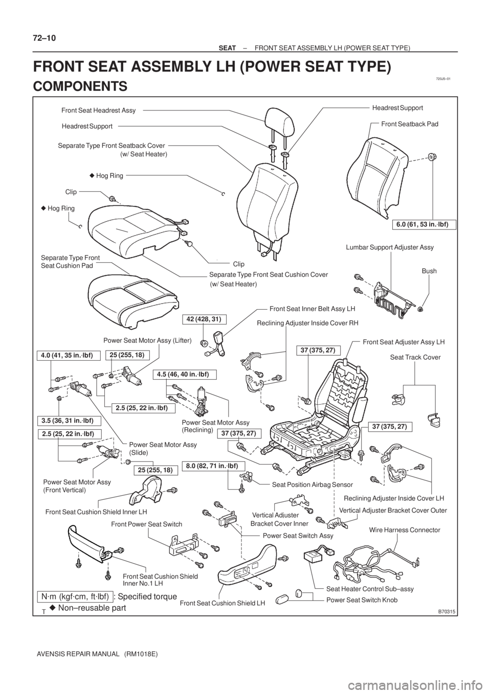
FRONT SEAT ASSEMBLY LH (POWER SEAT TYPE)
COMPONENTS
Page 3334 of 5135
720JH±01
������
������
B70589
A
B
1 21 2 3 4 5
(k�)
65�
18� 0 0 0.42 ± 0.28 4.08 ± 2.72
ON OFF 65�
B70591
1 21 2 3 4 5 A
B
± SEATSEAT HEATER SYSTEM
72±37
AVENSIS REPAIR MANUAL (RM1018E)
INSPECTION
1. LH side:
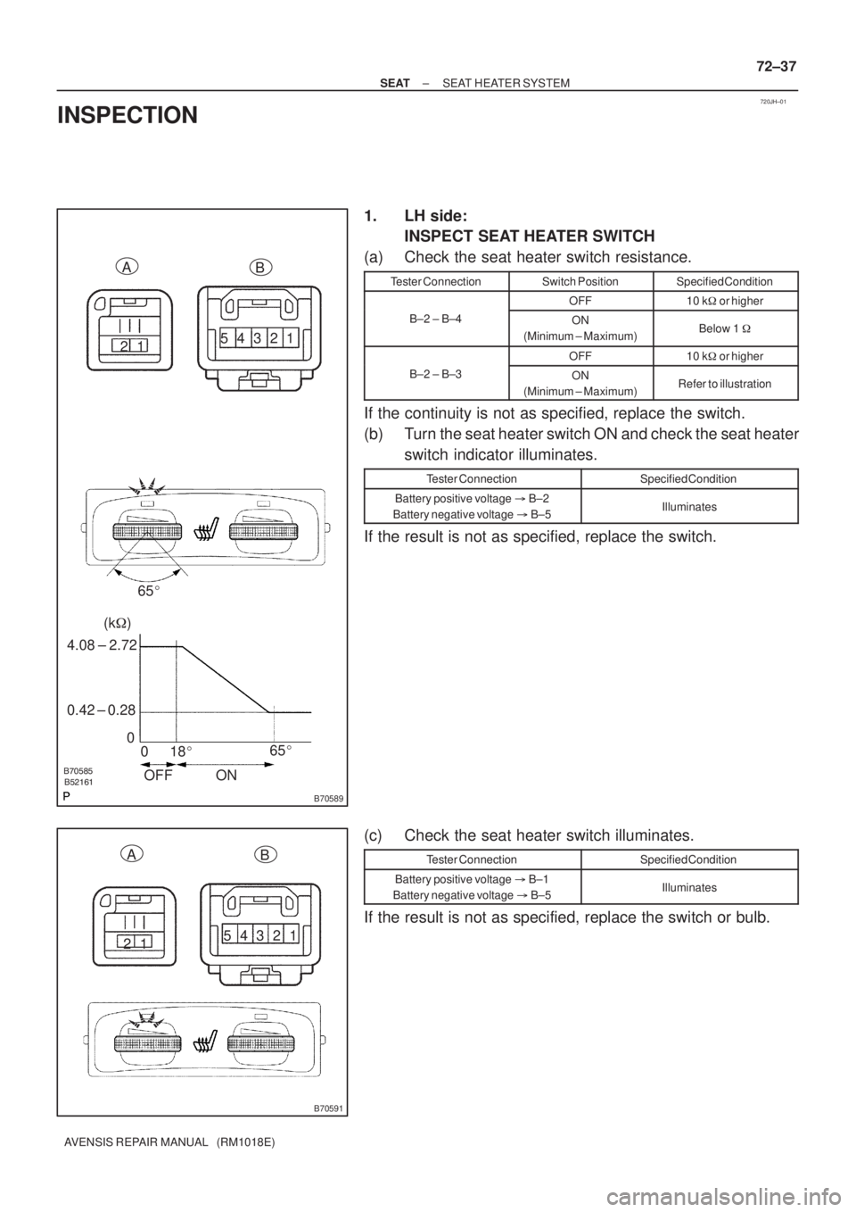
INSPECT SEAT HEATER SWITCH
(a) Check the seat heater switch resistance.
Tester ConnectionSwitch PositionSpecified Condition
OFF10 k�or higher
B±2 ± B±4ON
(Minimum ± Maximum)Below 1 �
OFF10 k�or higher
B±2 ± B±3ON
(Minimum ± Maximum)Refer to illustration
If the continuity is not as specified, replace the switch.
(b) Turn the seat heater switch ON and check the seat heater
switch indicator illuminates.
Tester ConnectionSpecified Condition
Battery positive voltage�B±2
Battery negative voltage�B±5Illuminates
If the result is not as specified, replace the switch.
(c) Check the seat heater switch illuminates.
Tester ConnectionSpecified Condition
Battery positive voltage�B±1
Battery negative voltage�B±5Illuminates
If the result is not as specified, replace the switch or bulb.
Page 3335 of 5135
������
������
B70880
1 21 2 3 4 5
(k�)
65�
18� 0 0 0.42 ± 0.28 4.08 ± 2.72
ON OFF65� AB
B70881
1 21 2 3 4 5 A
B
72±38
± SEATSEAT HEATER SYSTEM
AVENSIS REPAIR MANUAL (RM1018E)
2. RH side:
INSPECT SEAT HEATER SWITCH
(a) Check the seat heater switch resistance.
Tester ConnectionSwitch PositionSpecified Condition
OFF10 k�or higher
B±2 ± A±1ON
(Minimum ± Maximum)Below 1 �
OFF10 k�or higher
B±2 ± A±2ON
(Minimum ± Maximum)Refer to illustration
If the continuity is not as specified, replace the switch.
(b) Turn the seat heater switch ON and check the seat heater
switch indicator illuminates.
Tester ConnectionSpecified Condition
Battery positive voltage�B±2
Battery negative voltage�B±5Illuminates
If the result is not as specified, replace the switch.
(c) Check the seat heater switch indicator illuminates.
Tester ConnectionSpecified Condition
Battery positive voltage�B±1
Battery negative voltage�B±5Illuminates
If the result is not as specified, replace the switch or bulb.
Page 3336 of 5135
B70436
12
B70436
12
1 2
B68349
AB
1 2
B68349
AB
B68374
21
5
3
± SEATSEAT HEATER SYSTEM
72±39
AVENSIS REPAIR MANUAL (RM1018E)
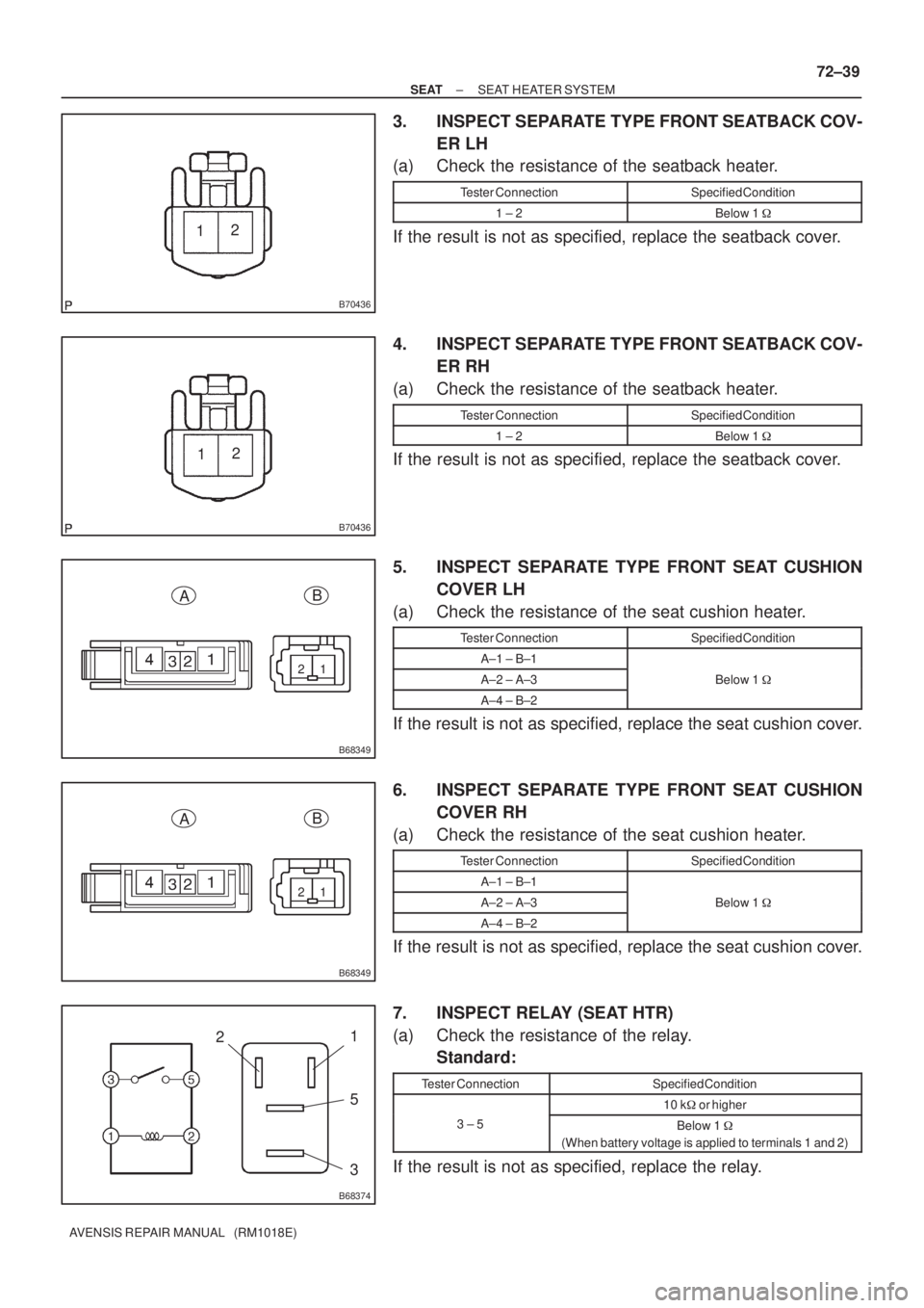
3. INSPECT SEPARATE TYPE FRONT SEATBACK COV-
ER LH
(a) Check the resistance of the seatback heater.
Tester ConnectionSpecified Condition
1 ± 2Below 1 �
If the result is not as specified, replace the seatback cover.
4. INSPECT SEPARATE TYPE FRONT SEATBACK COV-
ER RH
(a) Check the resistance of the seatback heater.
Tester ConnectionSpecified Condition
1 ± 2Below 1 �
If the result is not as specified, replace the seatback cover.
5. INSPECT SEPARATE TYPE FRONT SEAT CUSHION
COVER LH
(a) Check the resistance of the seat cushion heater.
Tester ConnectionSpecified Condition
A±1 ± B±1
A±2 ± A±3Below 1 �
A±4 ± B±2
If the result is not as specified, replace the seat cushion cover.
6. INSPECT SEPARATE TYPE FRONT SEAT CUSHION
COVER RH
(a) Check the resistance of the seat cushion heater.
Tester ConnectionSpecified Condition
A±1 ± B±1
A±2 ± A±3Below 1 �
A±4 ± B±2
If the result is not as specified, replace the seat cushion cover.
7. INSPECT RELAY (SEAT HTR)
(a) Check the resistance of the relay.
Standard:
Tester ConnectionSpecified Condition
10 k�or higher
3 ± 5Below 1 �
(When battery voltage is applied to terminals 1 and 2)
If the result is not as specified, replace the relay.
Page 3459 of 5135
010BA±12
01±12
± INTRODUCTIONTERMS
1AZ±FSE ENGINE REPAIR MANUAL (RM1019E)
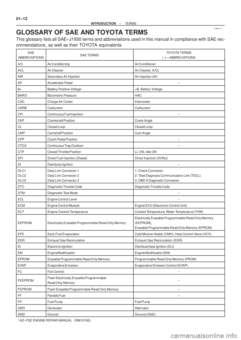
GLOSSARY OF SAE AND TOYOTA TERMS
This glossary lists all SAE±J1930 terms and abbreviations used in this manual in compliance with SAE rec-
ommendations, as well as their TOYOTA equivalents.
SAE
ABBREVIATIONSSAE TERMSTOYOTA TERMS
( )±±ABBREVIATIONS
A/CAir ConditioningAir Conditioner
ACLAir CleanerAir Cleaner, A/CL
AIRSecondary Air InjectionAir Injection (AI)
APAccelerator Pedal±
B+Battery Positive Voltage+B, Battery Voltage
BAROBarometric PressureHAC
CACCharge Air CoolerIntercooler
CARBCarburetorCarburetor
CFIContinuous Fuel Injection±
CKPCrankshaft PositionCrank Angle
CLClosed LoopClosed Loop
CMPCamshaft PositionCam Angle
CPPClutch Pedal Position±
CTOXContinuous Trap Oxidizer±
CTPClosed Throttle PositionLL ON, Idle ON
DFIDirect Fuel Injection (Diesel)Direct Injection (DI/INJ)
DIDistributor Ignition±
DLC1
DLC2
DLC3Data Link Connector 1
Data Link Connector 2
Data Link Connector 31: Check Connector
2: Total Diagnosis Communication Link (TDCL)
3: OBD II Diagnostic Connector
DTCDiagnostic Trouble CodeDiagnostic Trouble Code
DTMDiagnostic Test Mode±
ECLEngine Control Level±
ECMEngine Control ModuleEngine ECU (Electronic Control Unit)
ECTEngine Coolant TemperatureCoolant Temperature, Water Temperature (THW)
EEPROMElectrically Erasable Programmable Read Only Memory
Electrically Erasable Programmable Read Only Memory
(EEPROM),
Erasable Programmable Read Only Memory (EPROM)
EFEEarly Fuel EvaporationCold Mixture Heater (CMH), Heat Control Valve (HCV)
EGRExhaust Gas RecirculationExhaust Gas Recirculation (EGR)
EIElectronic IgnitionDistributorless Ignition (DLI)
EMEngine ModificationEngine Modification (EM)
EPROMErasable Programmable Read Only MemoryProgrammable Read Only Memory (PROM)
EVAPEvaporative EmissionEvaporative Emission Control (EVAP)
FCFan Control±
FEEPROMFlash Electrically Erasable Programmable
Read Only Memory±
FEPROMFlash Erasable Programmable Read Only Memory±
FFFlexible Fuel±
FPFuel PumpFuel Pump
GENGeneratorAlternator
GNDGroundGround (GND)
Page 3512 of 5135
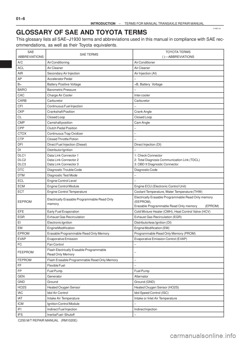
010BZ±02
01±6
± INTRODUCTIONTERMS FOR MANUAL TRANSAXLE REPAIR MANUAL
C250 M/T REPAIR MANUAL (RM1020E)
GLOSSARY OF SAE AND TOYOTA TERMS
This glossary lists all SAE±J1930 terms and abbreviations used in this manual in compliance with SAE rec-
ommendations, as well as their Toyota equivalents.
SAE
ABBREVIATIONSSAE TERMSTOYOTA TERMS
( )±±ABBREVIATIONS
A/CAir ConditioningAir Conditioner
ACLAir CleanerAir Cleaner
AIRSecondary Air InjectionAir Injection (AI)
APAccelerator Pedal±
B+Battery Positive Voltage+B, Battery Voltage
BAROBarometric Pressure±
CACCharge Air CoolerInter cooler
CARBCarburetorCarburetor
CFIContinuous Fuel Injection±
CKPCrankshaft PositionCrank Angle
CLClosed LoopClosed Loop
CMPCamshaft positionCam Angle
CPPClutch Pedal Position±
CTOXContinuous Trap Oxidizer±
CTPClosed Throttle Potion±
DFIDirect Fuel Injection (Diesel)Direct Injection (DI)
DIDistributor Ignition±
DLC1
DLC2
DLC3Data Link Connector 1
Data Link Connector 2
Data Link Connector 31: Check Connector
2: Total Diagnosis Communication Link (TDCL)
3: OBD II Diagnostic Connector
DTCDiagnostic Trouble CodeDiagnostic Code
DTMDiagnostic Test Mode±
ECLEngine Control Level±
ECMEngine Control ModuleEngine ECU (Electronic Control Unit)
ECTEngine Control TemperatureCoolant Temperature, Water Temperature (THW)
EEPROMElectrically Erasable Programmable Read Only
memoryElectrically Erasable Programmable Read Only memory
(EEPROM),
Erasable Programmable Read Only memory (EPROM)
EFEEarly Fuel EvaporationCold Mixture Heater (CMH), Heat Control Valve (HCV)
EGRExhaust Gas RecirculationExhaust Gas Recirculation (EGR)
EIElectronic IgnitionDistributorless Ignition (DI)
EMEngine ModificationEngine Modification (EM)
EPROMErasable Programmable Read Only MemoryProgrammable Read Only Memory (PROM)
EVAPEvaporative EmissionEvaporative Emission Control (EVAP)
FCFan Control±
FEEPROMFlash Electrically Erasable Programmable
Read Only Memory±
FEPROMFlash Erasable Programmable Read Only Memory±
FFFlexible Fuel±
FPFuel PumpFuel Pump
GENGeneratorAlternator
GNDGroundGround (GND)
HO2SHeated Oxygen SensorHeated Oxygen Sensor (HO2S)
IACIdol Air ControlIdol Speed Control (ISC)
IATIntake Air TemperatureIntake or Inlet Air Temperature
ICMIgnition Control Module±
IFIIndirect Fuel InjectionIndirect Injection
IFSInertia Fuel±Shutoff±
Page 3573 of 5135
90�11 0�
C58905
C80408
Match
marks
C67982
41±70
± MANUAL TRANSMISSION/TRANSAXLEDIFFERENTIAL CASE ASSY (C250)
C250 M/T REPAIR MANUAL (RM1020E)
13. INSTALL FRONT DIFFERENTIAL RING GEAR
(a) Using a heater, heat the front differential ring gear to 90
± 110 �C (194.0 ± 230.0 �F. )
(b) Clean the contact surface of the front differential case.
(c) Aligning the both match marks, quickly install the front dif-
ferential ring gear to the front differential case.
(d) Install the 8 bolts.
Torque: 77 N�m (790 kgf�cm, 57 ft�lbf)
14. INSTALL SPEEDOMETER DRIVE (MTM) GEAR
(a) install the speedometer drive gear to the front differential
case.
Page 3598 of 5135
C81323
C81324
D25177
C81325
���
C81326
± AUTOMATIC TRANSMISSION / TRANSFRONNT DIFFERENTIAL ASSY (U34#E Series)
40±75
U340E A/T REPAIR MANUAL (RM824E)
13. INSTALL FRONT DIFFERENTIAL PINION SHAFT
STRAIGHT PIN
[ 41342A / 4301 ]
(a) Using a pin punch and a hammer, install the pinion shaft
straight pin.
(b) Using a chisel and a hammer, stake the differential case.
14. INSTALL FRONT DIFFERENTIAL RING GEAR
[ 41221 / 4301 ]
(a) Using ATF and heater, hear the front differential ring gear
to 90 ± 110 �C (194.0 ± 230.0 �F).
(b) Clean the contact surface of the front differential case.
(c) Install the 4 lock plates and 8 bolts.
Torque: 88 N�m (900 kgf�cm, 65 ft�lbf)
(d) Using SST, stake the ring gear lock plate.
SST 09930±00010