Page 5068 of 5135

A76724
A76714
A77338
– ENGINE MECHANICALPARTIAL ENGINE ASSY (1ZZ–FE/3ZZ–FE)(From
February, 2004)14–11
AVENSIS REPAIR MANUAL SUPPLEMENT
(RM1098E)
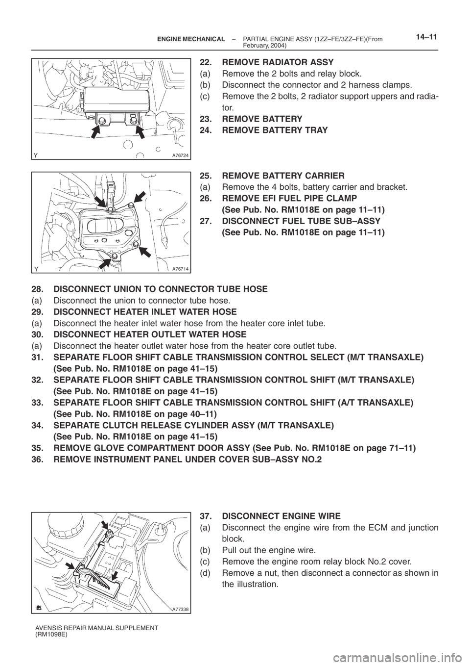
22. REMOVE RADIATOR ASSY
(a) Remove the 2 bolts and relay block.
(b) Disconnect the connector and 2 harness clamps.
(c) Remove the 2 bolts, 2 radiator support uppers and radia-
tor.
23. REMOVE BATTERY
24. REMOVE BATTERY TRAY
25. REMOVE BATTERY CARRIER
(a) Remove the 4 bolts, battery carrier and bracket.
26. REMOVE EFI FUEL PIPE CLAMP
(See Pub. No. RM1018E on page 11–11)
27. DISCONNECT FUEL TUBE SUB–ASSY
(See Pub. No. RM1018E on page 11–11)
28. DISCONNECT UNION TO CONNECTOR TUBE HOSE
(a) Disconnect the union to connector tube hose.
29. DISCONNECT HEATER INLET WATER HOSE
(a) Disconnect the heater inlet water hose from the heater core inlet tube.
30. DISCONNECT HEATER OUTLET WATER HOSE
(a) Disconnect the heater outlet water hose from the heater core outlet tube.
31. SEPARATE FLOOR SHIFT CABLE TRANSMISSION CONTROL SELECT (M/T TRANSAXLE)
(See Pub. No. RM1018E on page 41–15)
32. SEPARATE FLOOR SHIFT CABLE TRANSMISSION CONTROL SHIFT (M/T TRANSAXLE)
(See Pub. No. RM1018E on page 41–15)
33. SEPARATE FLOOR SHIFT CABLE TRANSMISSION CONTROL SHIFT (A/T TRANSAXLE)
(See Pub. No. RM1018E on page 40–11)
34. SEPARATE CLUTCH RELEASE CYLINDER ASSY (M/T TRANSAXLE)
(See Pub. No. RM1018E on page 41–15)
35. REMOVE GLOVE COMPARTMENT DOOR ASSY (See Pub. No. RM1018E on page 71–11)
36. REMOVE INSTRUMENT PANEL UNDER COVER SUB–ASSY NO.2
37. DISCONNECT ENGINE WIRE
(a) Disconnect the engine wire from the ECM and junction
block.
(b) Pull out the engine wire.
(c) Remove the engine room relay block No.2 cover.
(d) Remove a nut, then disconnect a connector as shown in
the illustration.
Page 5076 of 5135
A76723
A64033
A64034
A64034
A64033
– ENGINE MECHANICALPARTIAL ENGINE ASSY (1ZZ–FE/3ZZ–FE)(From
February, 2004)14–19
AVENSIS REPAIR MANUAL SUPPLEMENT
(RM1098E)
85. REMOVE EXHAUST MANIFOLD
(a) Remove the 5 nuts, then remove the exhaust manifold
and gasket.
86. REMOVE ENGINE COOLANT TEMPERATURE
SENSOR
(a) Using SST, remove the engine coolant temperature sen-
sor.
SST 09817–33190
87. REMOVE RADIO SETTING CONDENSER
(a) Remove the bolt and condenser.
88. REMOVE WATER BY–PASS HOSE NO.2
89. REMOVE RADIATOR HOSE INLET
90. REMOVE HEATER INLET WATER HOSE
91. REPLACE PARTIAL ENGINE ASSY
92. INSTALL RADIO SETTING CONDENSER
(a) Install the condenser with the bolt.
Torque: 10 N⋅m (102 kgf⋅cm, 7 ft⋅lbf)
93. INSTALL ENGINE COOLANT TEMPERATURE
SENSOR
(a) Install a new gasket onto the engine coolant temperature
sensor.
(b) Using SST, install the engine coolant temperature sensor.
SST 09817–33190
Torque: 20 N⋅m (204 kgf⋅cm, 15 ft⋅lbf)
Page 5097 of 5135
B66033
B660325 Clamps
or
or or
or
or
or 71–12
– INSTRUMENT PANEL/METERINSTRUMENT PANEL SUB–ASSY LOWER (From
February, 2004)
AVENSIS REPAIR MANUAL SUPPLEMENT
(RM1098E)
34. REMOVE HEATER TO REGISTER DUCT NO.2
(a) Remove the screw , clip and the heater to register duct
No.2.
35. REMOVE INSTRUMENT PANEL LOWER ASSY
(a) Disconnect the hood lock control cable.
(b) Using a clip remover, remove the 2 clips.
(c) Remove the 2 bolts and 7 screws or .
(d) Disengage the 5 wire harness clamps.
(e) Remove the instrument panel lower assy.
36. REMOVE OUTER MIRROR SWITCH ASSY W/BEZEL
37. REMOVE FUSE BOX OPENING COVER
38. REMOVE GLOVE BOX LAMP ASSY
39. REMOVE INSTRUMENT PANEL BRACKET SUB–ASSY CENTER
(a) Remove the screw and the instrument panel bracket sub–assy center.