Page 567 of 5135
A81699PBE2
E13
ECM Connector
VC
123
A72877
PIM
E2
Brake Booster Pressure
Sensor Connector Wire Harness SideB2
VC
± DIAGNOSTICSSFI SYSTEM (1AZ±FSE)
05±461
AVENSIS REPAIR MANUAL (RM1018E)
4 CHECK HARNESS AND CONNECTOR(ECM ± BRAKE BOOSTER PRESSURE
SENSOR)
(a) Disconnect the E13 ECM connector.
(b) Disconnect the B2 brake booster pressure sensor con-
nector.
(c) Check for continuity between the wire harness side con-
nectors.
Standard (Check for open):
Symbols (Terminal No.)Specified condition
VC (E13±18) ± VC (B2±3)
PB (E13±26) ± PIM (B2±2)Continuity
E2 (E13±28) ± E2 (B2±1)
y
Standard (Check for short):
Symbols (Terminal No.)Specified condition
VC (E13±18) or VC (B2±3) ± Body groundNo continuityPB (E13±26) or PIM (B2±2) ± Body groundNo continuity
NG REPAIR OR REPLACE HARNESS OR
CONNECTOR
OK
REPLACE BRAKE BOOSTER PRESSURE SENSOR
Page 572 of 5135

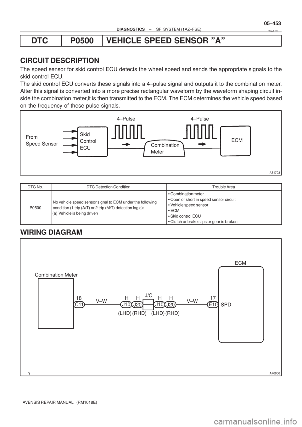
A81703
From
Speed SensorSkid
Control
ECU4±Pulse
Combination
MeterECM 4±Pulse
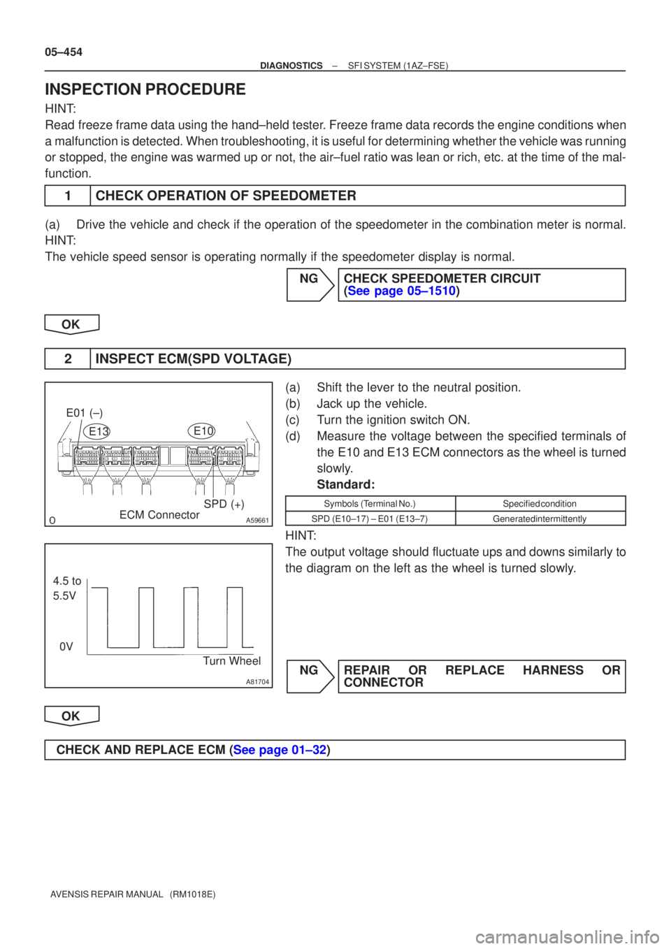
A76866
Combination MeterECM
C11V±W
SPD 17
V±W
E10 J/C
18 H
J10
(LHD)J20H
(RHD)H
J10
(LHD)J20H
(RHD)
± DIAGNOSTICSSFI SYSTEM (1AZ±FSE)
05±453
AVENSIS REPAIR MANUAL (RM1018E)
DTC P0500 VEHICLE SPEED SENSOR ºAº
CIRCUIT DESCRIPTION
The speed sensor for skid control ECU detects the wheel speed and sends the appropriate signals to the
skid control ECU.
The skid control ECU converts these signals into a 4±pulse signal and outputs it to the combination meter.
After this signal is converted into a more precise rectangular waveform by the waveform shaping circuit in-
side the combination meter,it is then transmitted to the ECM. The ECM determines the vehicle speed based
on the frequency of these pulse signals.
DTC No.DTC Detection ConditionTrouble Area
P0500
No vehicle speed sensor signal to ECM under the following
condition (1 trip (A/T) or 2 trip (M/T) detection logic):
(a) Vehicle is being driven
�Combination meter
�Open or short in speed sensor circuit
�Vehicle speed sensor
�ECM
�Skid control ECU
�Clutch or brake slips or gear is broken
WIRING DIAGRAM
05CJ6±01
Page 573 of 5135

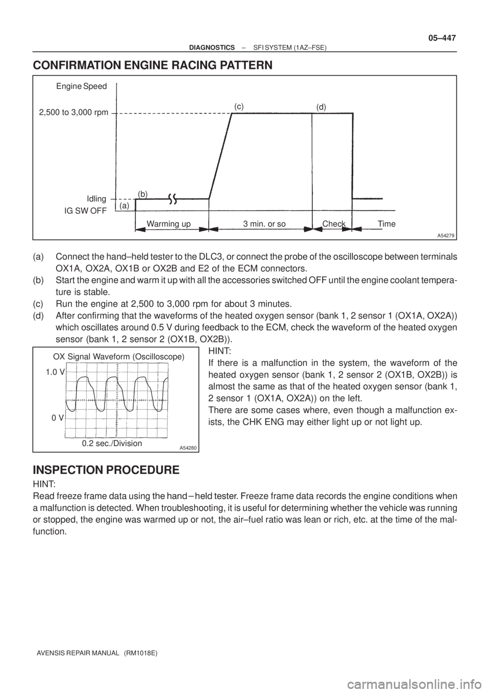
A59661
E01 (±)SPD (+)
ECM Connector
E13
E10
A81704
4.5 to
5.5V
0V Turn Wheel
05±454
±
DIAGNOSTICS SFI SYSTEM(1AZ±FSE)
AVENSIS REPAIR MANUAL (RM1018E)
INSPECTION PROCEDURE
HINT:
Read freeze frame data using the hand±held tester. Freeze frame data records the engine conditions when
a malfunction is detected. When troubleshooting, it is useful for determi\
ning whether the vehicle was running
or stopped, the engine was warmed up or not, the air±fuel ratio was lea\
n or rich, etc. at the time of the mal-
function.
1CHECK OPERATION OF SPEEDOMETER
(a)Drive the vehicle and check if the operation of the speedometer in the combination meter is normal.
HINT:
The vehicle speed sensor is operating normally if the speedometer displa\
y is normal. NGCHECK SPEEDOMETER CIRCUIT (See page 05±1510)
OK
2INSPECT ECM(SPD VOLTAGE)
(a)Shift the lever to the neutral position.
(b)Jack up the vehicle.
(c)Turn the ignition switch ON.
(d)Measure the voltage between the specified terminals of the E10 and E13 ECM connectors as the wheel is turned
slowly.
Standard:
Symbols (Terminal No.)Specified condition
SPD (E10±17) ± E01 (E13±7)Generated intermittently
HINT:
The output voltage should fluctuate ups and downs similarly to
the diagram on the left as the wheel is turned slowly.
NGREPAIR OR REPLACE HARNESS OR CONNECTOR
OK
CHECK AND REPLACE ECM (See page 01±32)
Page 578 of 5135

A54278
Waveform of Heated Oxygen
Sensor before CatalystNormal CatalystWaveform of Heated
Oxygen Sensor
after Catalyst
05±446
± DIAGNOSTICSSFI SYSTEM (1AZ±FSE)
AVENSIS REPAIR MANUAL (RM1018E)
DTC P0420 CATALYST SYSTEM EFFICIENCY BELOW
THRESHOLD (BANK 1)
DTC P0430 CATALYST SYSTEM EFFICIENCY BELOW
THRESHOLD (BANK 2)
CIRCUIT DESCRIPTION
The ECM compares the waveform of the heated oxygen sensor located before the catalyst with the wave-
form of the heated oxygen sensor located after the catalyst to determine whether or not the catalyst perfor-
mance has deteriorated.
The air±fuel ratio feedback compensation keeps the waveform of the heated oxygen sensor before the cata-
lyst repeatedly changing back and forth from rich to lean.
If the catalyst is functioning normally, the waveform of the heated oxygen sensor after the catalyst switches
back and forth between rich and lean much more slowly than the waveform of the heated oxygen sensor
before the catalyst.
But when both waveforms change at a similar rate, it indicates that the catalyst performance has deterio-
rated.
DTC No.DTC Detection ConditionTrouble Area
P0420
P0430
After engine and catalyst are warmed up, and while vehicle is
driven within set value and engine speed range, waveforms of
heated oxygen sensors have the same amplitude
(2 trip detection logic)�Gas leakage in exhaust system
�Heated oxygen sensor
�Three±way catalytic converter (inside exhaust manifold)
HINT:
�Bank 1 refers to the No. 1 and No. 4 cylinders.
�Bank 2 refers to the No. 2 and No. 3 cylinders.
�Sensor 1 refers to the sensor closest to the engine assembly.
�Sensor 2 refers to the sensor farthest away from the engine assembly.
05CKM±01
Page 579 of 5135

A54279
Engine Speed
2,500 to 3,000 rpm
Idling
IG SW OFF(a)
Time Warming up 3 min. or so Check (b)(c)
(d)
A54280
OX Signal Waveform (Oscilloscope)
1.0 V
0 V
0.2 sec./Division
± DIAGNOSTICSSFI SYSTEM (1AZ±FSE)
05±447
AVENSIS REPAIR MANUAL (RM1018E)
CONFIRMATION ENGINE RACING PATTERN
(a) Connect the hand±held tester to the DLC3, or connect the probe of the oscilloscope between terminals
OX1A, OX2A, OX1B or OX2B and E2 of the ECM connectors.
(b) Start the engine and warm it up with all the accessories switched OFF until the engine coolant tempera-
ture is stable.
(c) Run the engine at 2,500 to 3,000 rpm for about 3 minutes.
(d) After confirming that the waveforms of the heated oxygen sensor (bank 1, 2 sensor 1 (OX1A, OX2A))
which oscillates around 0.5 V during feedback to the ECM, check the waveform of the heated oxygen
sensor (bank 1, 2 sensor 2 (OX1B, OX2B)).
HINT:
If there is a malfunction in the system, the waveform of the
heated oxygen sensor (bank 1, 2 sensor 2 (OX1B, OX2B)) is
almost the same as that of the heated oxygen sensor (bank 1,
2 sensor 1 (OX1A, OX2A)) on the left.
There are some cases where, even though a malfunction ex-
ists, the CHK ENG may either light up or not light up.
INSPECTION PROCEDURE
HINT:
Read freeze frame data using
�� ��
���� �
��
��� �reeze frame data records the engine conditions when
a malfunction is detected. When troubleshooting, it is useful for determining whether the vehicle was running
or stopped, the engine was warmed up or not, the air±fuel ratio was lean or rich, etc. at the time of the mal-
function.
Page 580 of 5135
05±448
±
DIAGNOSTICS SFI SYSTEM(1AZ±FSE)
AVENSIS REPAIR MANUAL (RM1018E)
1CHECK OTHER DTC OUTPUT(IN ADDITION TO P0420 AND/OR P0430)
(a)Read the DTC using the hand±held tester. Result:
Display (DTC output)Proceed to
Only ºP0420 and/or P0430º are outputA
ºP0420 or P0430º and other DTCs are outputB
HINT:
If any other codes besides ºP0420 and/or P0430º are output, perform \
the troubleshooting for those DTCs
first.
BGO TO RELEVANT DTC CHART (See page 05±309)
A
2CHECK FOR EXHAUST GAS LEAKS
NGREPAIR OR REPLACE EXHAUST GAS LEAKAGE POINT
OK
3CHECK HEATED OXYGEN SENSOR(BANK 1, 2 SENSOR 1) (See page 05±363)
NG REPLACE HEATED OXYGEN SENSOR
OK
4CHECK HEATED OXYGEN SENSOR(BANK 1, 2 SENSOR 2) (See page 05±388)
NG REPLACE HEATED OXYGEN SENSOR
OK
REPLACE THREE±WAY CATALYTIC CONVERTER (EXHAUST MANIFOLD)
Page 582 of 5135
A73818
Crankshaft
Position
Sensor
Camshaft
Position
Sensor
Various
SensorIGT1
IGF
IGT2
IGT3
IGT4 ECM
IgniterFrom Battery
Ignition Coil
TA C
To Tachometer
No.2 Ignition
Coil with Igniter
No.3 Ignition
Coil with Igniter
No.4 Ignition
Coil with IgniterNo.1 Ignition Coil with Igniter
Spark Plug
No.1 Cylinder
No.4 Cylinder No.2 Cylinder
No.3 Cylinder 05±440
± DIAGNOSTICSSFI SYSTEM (1AZ±FSE)
AVENSIS REPAIR MANUAL (RM1018E)DTC No.
DTC Detection ConditionTrouble Area
P0351
P0352
P0353
P0354
No IGF signal to ECM while engine is running
�Ignition system
�Open or short in IGF and IGT circuit from ignition coil with
igniter to ECM (ignition coil circuit 1 through 4)
�Ignition coil with igniter (ignition coil 1 through 4)
�IG2 relay
�ECM
Page 599 of 5135
05±492
± DIAGNOSTICSSFI SYSTEM (1AZ±FSE)
AVENSIS REPAIR MANUAL (RM1018E)
DTC P2120 THROTTLE/PEDAL POSITION
SENSOR/SWITCH ºDº CIRCUIT
DTC P2122 THROTTLE/PEDAL POSITION
SENSOR/SWITCH ºDº CIRCUIT LOW INPUT
DTC P2123 THROTTLE/PEDAL POSITION
SENSOR/SWITCH ºDº CIRCUIT HIGH INPUT
DTC P2125 THROTTLE/PEDAL POSITION
SENSOR/SWITCH ºEº CIRCUIT
DTC P2127 THROTTLE/PEDAL POSITION
SENSOR/SWITCH ºEº CIRCUIT LOW INPUT
DTC P2128 THROTTLE/PEDAL POSITION
SENSOR/SWITCH ºEº CIRCUIT HIGH INPUT
DTC P2138 THROTTLE/PEDAL POSITION
SENSOR/SWITCH ºDº/ºEº VOLTAGE
CORRELATION
HINT:
This is procedure of accelerator pedal position sensor.
05CKT±01