Page 529 of 5135

AVENSIS REPAIR MANUAL (RM1018E)
DTC P0171 SYSTEM TOO LEAN (BANK 1)
DTC P0172 SYSTEM TOO RICH (BANK 1)
DTC P0174 SYSTEM TOO LEAN (BANK 2)
DTC P0175 SYSTEM")
05±394
± DIAGNOSTICSSFI SYSTEM (1AZ±FSE)
AVENSIS REPAIR MANUAL (RM1018E)
DTC P0171 SYSTEM TOO LEAN (BANK 1)
DTC P0172 SYSTEM TOO RICH (BANK 1)
DTC P0174 SYSTEM TOO LEAN (BANK 2)
DTC P0175 SYSTEM TOO RICH (BANK 2)
CIRCUIT DESCRIPTION
The fuel trim is related to the feedback compensation value, not to the basic injection time. The fuel trim in-
cludes the short±term fuel trim and the long±term fuel trim.
The short±term fuel trim is the short±term fuel compensation used to maintain the air±fuel ratio at stoichio-
metric air±fuel ratio. The signal from the heated oxygen sensor indicates whether the air±fuel ratio is RICH
or LEAN compared to the stoichiometric air±fuel ratio. This variance triggers a reduction in the fuel volume
if the air±fuel ratio is RICH, and an increase in the fuel volume if it is LEAN.
The long±term fuel trim is the overall fuel compensation carried out in long±term to compensate for a continu-
al deviation of the short±term fuel trim from the central value, due to individual engine differences, wear over-
time and changes in the operating environment.
If both the short±term fuel trim and the long±term fuel trim are LEAN or RICH beyond a certain value, it is
detected as a malfunction and the CHK ENG is illuminated.
DTC No.DTC Detection ConditionTrouble Area
P0171
P0174When air±fuel ratio feedback is stable after warming up engine,
fuel trim is considerably in error on LEAN side
(2 trip detection logic)
�Air induction system
�Injector blockage
�Mass air flow meter
�Manifold absolute pressure sensor
�Engine coolant temperature sensor
�Fuel pressure
�Gas leakage in exhaust system
�Open or short in heated oxygen sensor (bank 1, 2 sensor 1)
circuit
�Heated oxygen sensor (bank 1, 2 sensor 1)
�Heated oxygen sensor heater (bank 1, 2 sensor 1)
�EFI relay
�PCV valve and hose
�PCV hose connection
�ECM
P0172
P0175When air±fuel ratio feedback is stable after warming up engine,
fuel trim is considerably in error on RICH side
(2 trip detection logic)
�Injector leakage blockage
�Mass air flow meter
�Manifold absolute pressure sensor
�Engine coolant temperature sensor
�Ignition system
�Fuel pressure
�Gas leakage in exhaust system
�Open or short in heated oxygen sensor (bank 1, 2 sensor 1)
circuit
�Heated oxygen sensor (bank 1, 2 sensor 1)
�ECM
HINT:
�When DTC ºP0171 or P0174º is recorded, the actual air±fuel ratio is on the LEAN side. When DTC
ºP0172 or P0175º is recorded, the actual air±fuel ratio is on the RICH side.
�If the vehicle runs out of fuel, the air±fuel ratio is LEAN and DTC ºP0171 or P0174º is recorded. The
CHK ENG then comes on.
05CKD±01
Page 530 of 5135

05±395
AVENSIS REPAIR MANUAL (RM1018E)
�If the total of the short±term fuel trim value and long±term fuel tri\
m value is within � 25 % (Engine cool-
ant temp")
±
DIAGNOSTICS SFI SYSTEM(1AZ±FSE)
05±395
AVENSIS REPAIR MANUAL (RM1018E)
�If the total of the short±term fuel trim value and long±term fuel tri\
m value is within � 25 % (Engine cool-
ant temperature is greater than 75 �C), the system is functioning normally.
�Bank 1 refers to the No. 1 and No. 4 cylinders.
�Bank 2 refers to the No. 2 and No. 3 cylinders.
WIRING DIAGRAM
Refer to DTC P0130 on page 05±363.
INSPECTION PROCEDURE
HINT:
Hand±held tester only:
Narrowing down the trouble area is possible by performing the ºA/F CONTROLº ACTIVE TEST (heated oxy-
gen sensor or other trouble areas can be distinguished).
(a) Perform ACTIVE TEST using the hand±held tester (A/F CONTROL).
HINT:
ºA/F CONTROLº is an ACTIVE TEST which changes the injection volume\
±12.5 % or +25 %.
(1) Connect the hand±held tester to the DLC3 on the vehicle.
(2) Turn the ignition switch ON.
(3) Warm up the engine by running the engine at 2,500 rpm for approximately 9\
0 sec.
(4) Select the item ºDIAGNOSIS / OBD/MOBD / ACTIVE TEST / A/F CONTROLº\
.
(5) Perform ºA/F CONTROLº with the engine in an idle condition (press\
the right or left button).
Result:
Heated oxygen sensor reacts in accordance with increase and decrease of injection volume:
+25 % � rich output: More than 0.55 V
±12.5 % � lean output: Less than 0.4 V
NOTICE:
There is a few seconds delay in the sensor 1 (front sensor) output. And there is about 20 seconds
delay in the sensor 2 (rear sensor).
Page 531 of 5135

Injection volume
Output voltage
Output voltage of heated oxy")
+25 %
±12.5 %
More than 0.55 V
Less than 0.4V
Case 1
Case 2
Case 3
Case 4
Output voltage of heated oxygen
sensor (sensor 1: front sensor)
Injection volume
Output voltage
Output voltage of heated oxygen
sensor (sensor 2: rear sensor)Mainly suspect
trouble area
OK
+25 %
±12.5 %
More than 0.55 V
Less than 0.4V
Injection volume
Output voltage
+25 %
±12.5 %
More than 0.55 V
Less than 0.4V
Injection volume
Output voltage
Sensor 1: front sensor
(sensor 1, heater, sensor 1
circuit)
+25 %
±12.5 %
More than 0.55 V
Less than 0.4V
Injection volume
Output voltage
+25 %
±12.5 %
Injection volume
Output voltage
NG
+25 %
±12.5 %
Injection volume
Output voltage
NG
+25 %
±12.5 %
Injection volume
Output voltage
NG
+25 %
±12.5 %
Injection volume
Output voltage
NGExtremely rich or lean actual
air±fuel ratio
(Injector, fuel pressure, gas
leakage in exhaust system,
etc.) OK
OK
OK
No reaction
No reaction
No reaction No reaction
�
Sensor 2: rear sensor
(sensor 2, heater, sensor 2
circuit) 05±396
± DIAGNOSTICSSFI SYSTEM (1AZ±FSE)
AVENSIS REPAIR MANUAL (RM1018E)
The following A/F CONTROL procedure enables the technician to check and graph the voltage outputs of
both the heated oxygen sensors.
For displaying the graph indication, enter ºACTIVE TEST / A/F CONTROL / USER DATAº, then select ºO2S
B1S1 and O2S B1S2º or ºO2S B2S1 and O2S B2S2º by pressing ºYESº button and push ºENTERº button
before pressing ºF4º button.
HINT:
�If different DTCs related to different systems that have terminal E2 as the ground terminal are output
simultaneously, terminal E2 may be open.
�Read freeze frame data using the hand±held tester. Freeze frame data records the engine conditions
when a malfunction is detected. When troubleshooting, it is useful for determining whether the vehicle
was running or stopped, the engine was warmed up or not, the air±fuel ratio was lean or rich, etc. at
the time of the malfunction.
�A high heated oxygen sensor (sensor 1) voltage (0.55 V or more) could be caused by a rich air fuel
mixture. Check for conditions that would cause the engine to run rich.
�A low heated oxygen sensor (sensor 1) voltage (0.4 V or less) could be caused by a lean air fuel mix-
ture. Check for conditions that would cause the engine to run lean.
Page 534 of 5135
(104)(140)(176) (32)(68)(212)������������
30
20
10
5
3
02040
0.1 1
0.3 0.2
0.5 2
6080100
±20
(±4)(104)(140)(176) (32)(68)(212)
A8")
������������
3020
10
5
3
02040
0.1 1
0.3 0.2
0.5 2
6080100
±20
(±4)(104)(140)(176) (32)(68)(212)������������
30
20
10
5
3
02040
0.1 1
0.3 0.2
0.5 2
6080100
±20
(±4)(104)(140)(176) (32)(68)(212)
A81700
Ohmmeter
Acceptable
TEMPERATURE �C ( �F)
RESISTANCE K �
±
DIAGNOSTICS SFI SYSTEM(1AZ±FSE)
05±399
AVENSIS REPAIR MANUAL (RM1018E)
5INSPECT ENGINE COOLANT TEMPERATURE SENSOR(RESISTANCE)
(a)Remove the engine coolant temperature sensor.
(b)Measure the resistance between the terminals.
Resistance:
2.32 to 2.59 k �at 20 �C (68 �F)
0.310 to 0.326 k �at 80 �C (176 �F)
NOTICE:
In case of checking the engine coolant temperature sensor
in the water, be careful not to allow water to go into the ter-
minals. After checking, dry the sensor.
HINT:
Alternate procedure: Connect an ohmmeter to the installed en-
gine coolant temperature sensor and read the resistance. Use
an infrared thermometer to measure the engine temperature in
the immediate vicinity of the sensor. Compare these values to
the resistance/temperature graph. Change the engine temper-
ature (warm up or allow to cool down) and repeat the test.
NGREPLACE ENGINE COOLANT TEMPERATURE SENSOR
OK
6CHECK FOR SPARK AND IGNITION (See page 18±12)
NG REPAIR OR REPLACE
OK
7CHECK FUEL PRESSURE(LOW PRESSURE) (See page 11±33)
NG CHECK AND REPLACE FUEL PUMP, PRESSURE REGULATOR, FUEL PIPE LINE AND
FILTER
OK
8CHECK FUEL PRESSURE(HIGH PRESSURE) (See page 11±33)
NG CHECK AND REPLACE FUEL PUMP, FUEL PRESSURE SENSOR, WIRING AND FUEL
LEAKAGE
OK
Page 536 of 5135

05±401
AVENSIS REPAIR MANUAL (RM1018E)
14READ VALUE OF HAND±HELD TESTER(OUTPUT VOLTAGE OF HEATED OXYGEN
SENSOR (BANK 1, 2 SENSOR 1))
(a)Warm up the heate")
P18349
±
DIAGNOSTICS SFI SYSTEM(1AZ±FSE)
05±401
AVENSIS REPAIR MANUAL (RM1018E)
14READ VALUE OF HAND±HELD TESTER(OUTPUT VOLTAGE OF HEATED OXYGEN
SENSOR (BANK 1, 2 SENSOR 1))
(a)Warm up the heated oxygen sensor (sensor 1) with the engine speed at 2,\
500 rpm for approximately
90 seconds.
(b)Read the output voltage of the heated oxygen sensor (sensor 1) during \
idling. The output voltage of heated oxygen sensor (sensor 1):
Alternates repeatedly between less than 0.4 V and more than 0.55 V (See the follo\
wing table).
NGGo to step 21
OK
15PERFORM CONFIRMATION DRIVING PATTERN (See page 05±363)
HINT:
Clear all DTCs prior to performing the confirmation driving pattern. GO
16 READ OUTPUT DTC(DTC P0171, P0172, P0174 AND/OR P0175 ARE OUTPUT AGAIN)
(a) Read the DTC using the hand±held tester.
Result:
Display (DTC output)Proceed to
DTC ºP0171, P0172, P0174 and/or P0175º are output againA
DTC ºP0171, P0172, P0174 and/or P0175º are not output againB
B Go to step 20
A
17 REPLACE HEATED OXYGEN SENSOR
GO
Page 538 of 5135
A62378
Component Side
+B
HT
E1
� �
� �B1S1 H7
A61830
+B
HT
E1 Component Side
B2S1 H9
B16200
± DIAGNOSTICSSFI SYSTEM (1AZ±FSE)
05±403
AVENSIS REPAIR MANUAL (RM1018E)
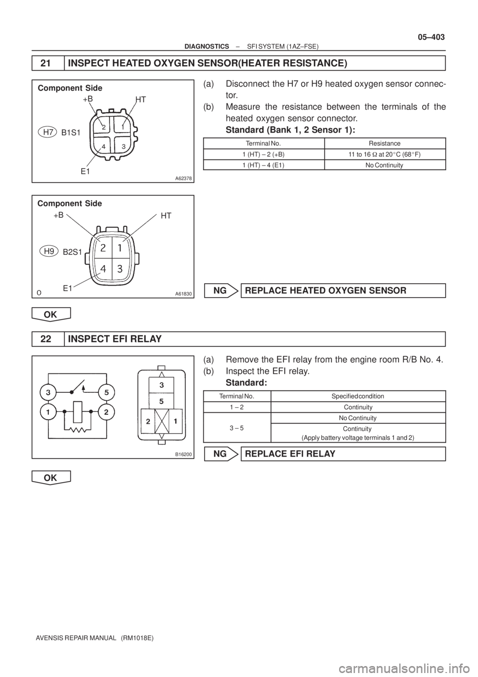
21 INSPECT HEATED OXYGEN SENSOR(HEATER RESISTANCE)
(a) Disconnect the H7 or H9 heated oxygen sensor connec-
tor.
(b) Measure the resistance between the terminals of the
heated oxygen sensor connector.
Standard (Bank 1, 2 Sensor 1):
Terminal No.Resistance
1 (HT) ± 2 (+B)11 to 16 � at 20�C (68�F)
1 (HT) ± 4 (E1)No Continuity
NG REPLACE HEATED OXYGEN SENSOR
OK
22 INSPECT EFI RELAY
(a) Remove the EFI relay from the engine room R/B No. 4.
(b) Inspect the EFI relay.
Standard:
Terminal No.Specified condition
1 ± 2Continuity
No Continuity
3 ± 5Continuity
(Apply battery voltage terminals 1 and 2)
NG REPLACE EFI RELAY
OK
Page 539 of 5135

Heated Oxy")
A76821
Wire Harness Side
B1S1B2S1 H7 H9
Heated Oxygen Sensor Connector OX
HT
OX
HT
E1E1
A76823
OX2A
ECM Connector E12
OX1A
HT2A HT1A
E2 E13
A72920
Reference (Bank 1 Sensor 1 System Drawing)
Heated Oxygen Sensor
EFI Relay
Heater
Sensor
OX1A HT1A
Duty
Control ECM
From
Battery
EFI Fuse
E2 EFI No. 2
Fuse
MREL OX HT
E1 +B
05±404
± DIAGNOSTICSSFI SYSTEM (1AZ±FSE)
AVENSIS REPAIR MANUAL (RM1018E)
23 CHECK HARNESS AND CONNECTOR(HEATED OXYGEN SENSOR ± ECM)
(a) Disconnect the H7 or H9 heated oxygen sensor connec-
tor.
(b) Disconnect the E12 and E13 ECM connectors.
(c) Check for continuity between the wire harness side con-
nectors.
Standard (Check for open):
Symbols (Terminal No.)Specified condition
OX (H7±3) ± OX1A (E12±22)
HT (H7±1) ± HT1A (E12±5)
E1 (H7±4) ± E2 (E13±28)ContinuityOX (H8±3) ± OX2A (E12±23)Continuity
HT (H8±1) ± HT2A (E12±4)
E1 (H8±4) ± E2 (E13±28)
Standard (Check for short):
Symbols (Terminal No.)Specified condition
OX (H7±3) or OX1A (E12±22) ± Body ground
HT (H7±1) or HT1A (E12±5) ± Body groundNo continuityOX (H8±3) or OX2A (E12±23) ± Body groundNo continuity
HT (H8±1) or HT2A (E12±4) ± Body ground
HINT:
�The OX1A and HT1A means the heated oxygen sensor
bank 1 sensor 1.
�The OX2A and HT2A means the heated oxygen sensor
bank 2 sensor 1.
NG REPAIR OR REPLACE HARNESS OR
CONNECTOR
OK
24 REPLACE HEATED OXYGEN SENSOR
GO
Page 541 of 5135
± DIAGNOSTICSSFI SYSTEM (1AZ±FSE)
05±363
AVENSIS REPAIR MANUAL (RM1018E)
DTC P0130 OXYGEN SENSOR CIRCUIT (BANK 1
SENSOR 1)
DTC P0150 OXYGEN SENSOR CIRCUIT (BANK 2
SENSOR 1)
DTC P2195 OXYGEN SENSOR SIGNAL STUCK LEAN
(BANK 1 SENSOR 1)
DTC P2196 OXYGEN SENSOR SIGNAL STUCK RICH
(BANK 1 SENSOR 1)
DTC P2197 OXYGEN SENSOR SIGNAL STUCK LEAN
(BANK 2 SENSOR 1)
DTC P2198 OXYGEN SENSOR SIGNAL STUCK RICH
(BANK 2 SENSOR 1)
05CK9±01

05±363
AVENSIS REPAIR MANUAL (RM1018E)
DTC P0130 OXYGEN SENSOR CIRCUIT (BANK 1
SENSOR 1)
DTC P0150 OXYGEN SENSOR CIRCUIT (BANK 2
SENSOR 1)
DTC P2195 OXYGEN SENSO")