Page 512 of 5135
A76872
K1
Knock SensorECM
KNK1
E12
(Shielded)
1 BR D
E
J13 J12 1
B B
J/C EKNK
E12 2
W
2
EEJ12
J13
D
E
BR BR 5 V
05±430
±
DIAGNOSTICS SFI SYSTEM(1AZ±FSE)
AVENSIS REPAIR MANUAL (RM1018E)
WIRING DIAGRAM
INSPECTION PROCEDURE
HINT:
Read freeze frame data using the hand±held tester. Freeze frame data records the engine conditions when
a malfunction is detected. When troubleshooting, it is useful for determi\
ning whether the vehicle was running
or stopped, the engine was warmed up or not, the air±fuel ratio was lea\
n or rich, etc. at the time of the mal-
function.
1READ OUTPUT DTC
(a)Clear the DTC (See page 05±294).
(b) Warm up the engine.
(c) Run the engine at 3,000 rpm for 10 seconds or more.
(d)Read the DTC (See page 05±294). Result :
Display (DTC output)Proceed to
Only ºP0325º is output againA
ºP0325, P0327 and/or P0328º are output againB
ºP0325, P0327 and/or P0328º are not output againC
B Go to step 3
C CHECK FOR INTERMITTENT PROBLEMS
A
Page 513 of 5135
A79596
A81695
KNK1
E12
ECM Connector
EKNK
A76969
KNK1 (+)EKNK (±)
E12
ECM Connector
±
DIAGNOSTICS SFI SYSTEM(1AZ±FSE)
05±431
AVENSIS REPAIR MANUAL (RM1018E)
2CHECK KNOCK SENSOR
(a)Check the knock sensor installation.
Torque: 20 N �m (204 kgf �cm, 15 ft �lbf)
NGTIGHTEN SENSOR
OK
REPLACE KNOCK SENSOR
3CHECK HARNESS AND CONNECTOR(ECM ± KNOCK SENSOR)
(a)Disconnect the E12 ECM connector.
(b)Measure the resistance between terminals KNK1 (E12±1) and EKNK (E12±2) of the ECM connector.
Resistance: 120 to 280 k � at 20 �C (68 �F)
NGGo to step 5
OK
4INSPECT ECM(KNK1 VOLTAGE)
(a)Disconnect the E12 ECM connector.
(b)Turn the ignition switch ON.
(c)Measure the voltage between terminals KNK1 (E12±1) and EKNK (E12±2) of the ECM terminals.
Voltage: 4.5 to 5.5 V
NGREPLACE ECM (See page 10±65)
OK
CHECK FOR INTERMITTENT PROBLEMS
NOTICE:
Fault may be intermittent. Check harness and connectors carefully and re\
sult.
Page 514 of 5135
A65174
Ohmmeter
05±432
± DIAGNOSTICSSFI SYSTEM (1AZ±FSE)
AVENSIS REPAIR MANUAL (RM1018E)
5 INSPECT KNOCK SENSOR
(a) Remove the knock sensor.
(b) Measure the resistance between the terminals.
Resistance: 120 to 280 k� at 20�C (68�F)
NG REPLACE KNOCK SENSOR
OK
REPAIR OR REPLACE HARNESS OR CONNECTOR
Page 520 of 5135

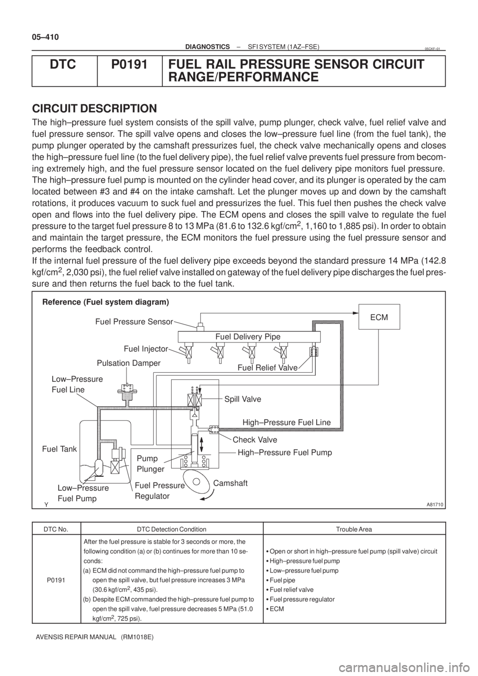
A81710
Camshaft
Fuel Relief ValveECM
Fuel Pressure Sensor
Pulsation Damper
Fuel Tank
Fuel Pressure
Regulator Fuel Injector
Spill Valve
High±Pressure Fuel Pump
Low±Pressure
Fuel PumpFuel Delivery Pipe Reference (Fuel system diagram)
Pump
Plunger
High±Pressure Fuel Line Low±Pressure
Fuel Line
Check Valve
05±410
± DIAGNOSTICSSFI SYSTEM (1AZ±FSE)
AVENSIS REPAIR MANUAL (RM1018E)
DTC P0191 FUEL RAIL PRESSURE SENSOR CIRCUIT
RANGE/PERFORMANCE
CIRCUIT DESCRIPTION
The high±pressure fuel system consists of the spill valve, pump plunger, check valve, fuel relief valve and
fuel pressure sensor. The spill valve opens and closes the low±pressure fuel line (from the fuel tank), the
pump plunger operated by the camshaft pressurizes fuel, the check valve mechanically opens and closes
the high±pressure fuel line (to the fuel delivery pipe), the fuel relief valve prevents fuel pressure from becom-
ing extremely high, and the fuel pressure sensor located on the fuel delivery pipe monitors fuel pressure.
The high±pressure fuel pump is mounted on the cylinder head cover, and its plunger is operated by the cam
located between #3 and #4 on the intake camshaft. Let the plunger moves up and down by the camshaft
rotations, it produces vacuum to suck fuel and pressurizes the fuel. This fuel then pushes the check valve
open and flows into the fuel delivery pipe. The ECM opens and closes the spill valve to regulate the fuel
pressure to the target fuel pressure 8 to 13 MPa (81.6 to 132.6 kgf/cm
2, 1,160 to 1,885 psi). In order to obtain
and maintain the target pressure, the ECM monitors the fuel pressure using the fuel pressure sensor and
performs the feedback control.
If the internal fuel pressure of the fuel delivery pipe exceeds beyond the standard pressure 14 MPa (142.8
kgf/cm
2, 2,030 psi), the fuel relief valve installed on gateway of the fuel delivery pipe discharges the fuel pres-
sure and then returns the fuel back to the fuel tank.
DTC No.DTC Detection ConditionTrouble Area
P0191
After the fuel pressure is stable for 3 seconds or more, the
following condition (a) or (b) continues for more than 10 se-
conds:
(a) ECM did not command the high±pressure fuel pump to
open the spill valve, but fuel pressure increases 3 MPa
(30.6 kgf/cm
2, 435 psi).
(b) Despite ECM commanded the high±pressure fuel pump to
open the spill valve, fuel pressure decreases 5 MPa (51.0
kgf/cm
2, 725 psi).
�Open or short in high±pressure fuel pump (spill valve) circuit
�High±pressure fuel pump
�Low±pressure fuel pump
�Fuel pipe
�Fuel relief valve
�Fuel pressure regulator
�ECM
05CKF±01
Page 525 of 5135

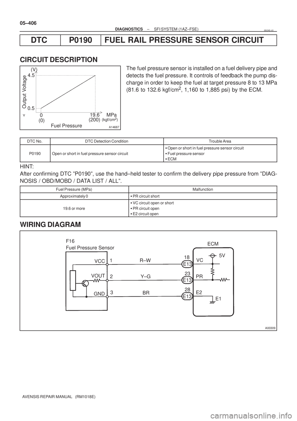
A14687
(V)
4.5
0.5
(0)019.6
(200)MPa
(kgf/cm2)
Output Voltage
Fuel Pressure
A00309
F16
Fuel Pressure Sensor
18
E13ECM
5V
E1 1 R±W
23
Y±G 2
3
BR28
E2 PRVC
VOUT
GNDE13
E13 VCC 05±406
± DIAGNOSTICSSFI SYSTEM (1AZ±FSE)
AVENSIS REPAIR MANUAL (RM1018E)
DTC P0190 FUEL RAIL PRESSURE SENSOR CIRCUIT
CIRCUIT DESCRIPTION
The fuel pressure sensor is installed on a fuel delivery pipe and
detects the fuel pressure. It controls of feedback the pump dis-
charge in order to keep the fuel at target pressure 8 to 13 MPa
(81.6 to 132.6 kgf/cm
2, 1,160 to 1,885 psi) by the ECM.
DTC No.DTC Detection ConditionTrouble Area
P0190Open or short in fuel pressure sensor circuit
�Open or short in fuel pressure sensor circuit
�Fuel pressure sensor
�ECM
HINT:
After confirming DTC ºP0190º, use the hand±held tester to confirm the delivery pipe pressure from ºDIAG-
NOSIS / OBD/MOBD / DATA LIST / ALLº.
Fuel Pressure (MPa)Malfunction
Approximately 0�PR circuit short
19.6 or more
�VC circuit open or short
�PR circuit open
�E2 circuit open
WIRING DIAGRAM
05CKE±01
Page 526 of 5135

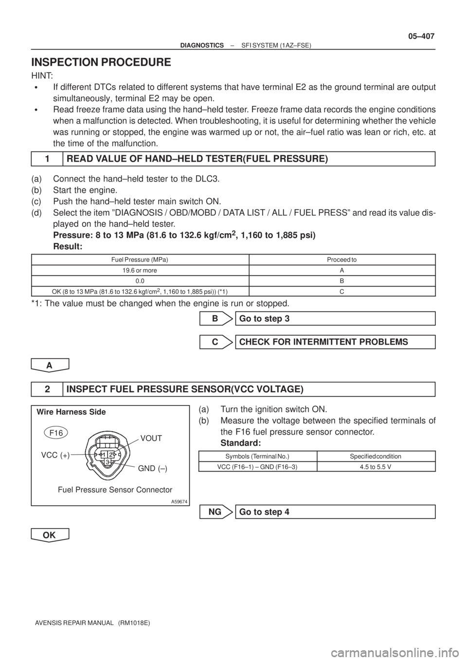
A59674
F16
VCC (+)
GND (±)
Fuel Pressure Sensor Connector Wire Harness Side
VOUT
± DIAGNOSTICSSFI SYSTEM (1AZ±FSE)
05±407
AVENSIS REPAIR MANUAL (RM1018E)
INSPECTION PROCEDURE
HINT:
�If different DTCs related to different systems that have terminal E2 as the ground terminal are output
simultaneously, terminal E2 may be open.
�Read freeze frame data using the hand±held tester. Freeze frame data records the engine conditions
when a malfunction is detected. When troubleshooting, it is useful for determining whether the vehicle
was running or stopped, the engine was warmed up or not, the air±fuel ratio was lean or rich, etc. at
the time of the malfunction.
1 READ VALUE OF HAND±HELD TESTER(FUEL PRESSURE)
(a) Connect the hand±held tester to the DLC3.
(b) Start the engine.
(c) Push the hand±held tester main switch ON.
(d) Select the item ºDIAGNOSIS / OBD/MOBD / DATA LIST / ALL / FUEL PRESSº and read its value dis-
played on the hand±held tester.
Pressure: 8 to 13 MPa (81.6 to 132.6 kgf/cm
2, 1,160 to 1,885 psi)
Result:
Fuel Pressure (MPa)Proceed to
19.6 or moreA
0.0B
OK (8 to 13 MPa (81.6 to 132.6 kgf/cm2, 1,160 to 1,885 psi)) (*1)C
*1: The value must be changed when the engine is run or stopped.
B Go to step 3
C CHECK FOR INTERMITTENT PROBLEMS
A
2 INSPECT FUEL PRESSURE SENSOR(VCC VOLTAGE)
(a) Turn the ignition switch ON.
(b) Measure the voltage between the specified terminals of
the F16 fuel pressure sensor connector.
Standard:
Symbols (Terminal No.)Specified condition
VCC (F16±1) ± GND (F16±3)4.5 to 5.5 V
NG Go to step 4
OK
Page 527 of 5135

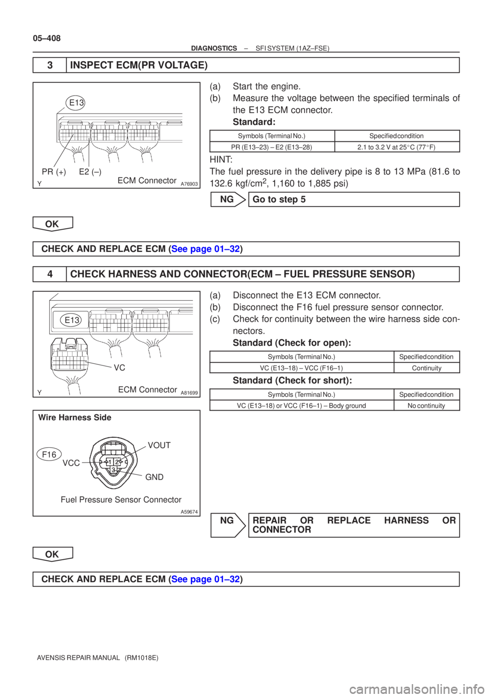
A76903
PR (+)E2 (±)ECM Connector
E13
A81699
VC
E13
ECM Connector
A59674
F16
VCC GND
Fuel Pressure Sensor Connector
Wire Harness Side
VOUT
05±408
±
DIAGNOSTICS SFI SYSTEM(1AZ±FSE)
AVENSIS REPAIR MANUAL (RM1018E)
3INSPECT ECM(PR VOLTAGE)
(a)Start the engine.
(b)Measure the voltage between the specified terminals of the E13 ECM connector.
Standard:
Symbols (Terminal No.)Specified condition
PR (E13±23) ± E2 (E13±28)2.1 to 3.2 V at 25 �C (77 �F)
HINT:
The fuel pressure in the delivery pipe is 8 to 13 MPa (81.6 to
132.6 kgf/cm
2, 1,160 to 1,885 psi)
NGGo to step 5
OK
CHECK AND REPLACE ECM (See page 01±32)
4CHECK HARNESS AND CONNECTOR(ECM ± FUEL PRESSURE SENSOR)
(a)Disconnect the E13 ECM connector.
(b)Disconnect the F16 fuel pressure sensor connector.
(c)Check for continuity between the wire harness side con- nectors.
Standard (Check for open):
Symbols (Terminal No.)Specified condition
VC (E13±18) ± VCC (F16±1)Continuity
Standard (Check for short):
Symbols (Terminal No.)Specified condition
VC (E13±18) or VCC (F16±1) ± Body groundNo continuity
NGREPAIR OR REPLACE HARNESS OR CONNECTOR
OK
CHECK AND REPLACE ECM (See page 01±32)
Page 528 of 5135
A81699PRE2
E13
ECM Connector
A59674
F16
GND
Fuel Pressure Sensor Connector Wire Harness Side
VOUT
± DIAGNOSTICSSFI SYSTEM (1AZ±FSE)
05±409
AVENSIS REPAIR MANUAL (RM1018E)
5 CHECK HARNESS AND CONNECTOR(ECM ± FUEL PRESSURE SENSOR)
(a) Disconnect the E13 ECM connector.
(b) Disconnect the F16 fuel pressure sensor connector.
(c) Check for continuity between the wire harness side con-
nectors.
Standard (Check for open):
Symbols (Terminal No.)Specified condition
PR (E13±23) ± VOUT (F16±2)ContinuityE2 (E13±28) ± GND (F16±3)Continuity
Standard (Check for short):
Symbols (Terminal No.)Specified condition
PR (E13±23) or VOUT (F16±2) ± Body groundNo continuity
NG REPAIR OR REPLACE HARNESS OR
CONNECTOR
OK
REPLACE FUEL PRESSURE SENSOR