Page 634 of 5135

±
DIAGNOSTICS ECD SYSTEM(1CD±FTV)
05±533
AVENSIS REPAIR MANUAL (RM1018E)
(c)Perform a simulation test (See page 01±22).
(d)Check the connector and terminal (See page 01±32).
(e)Wiggle the harness and connector (See page 01±32).
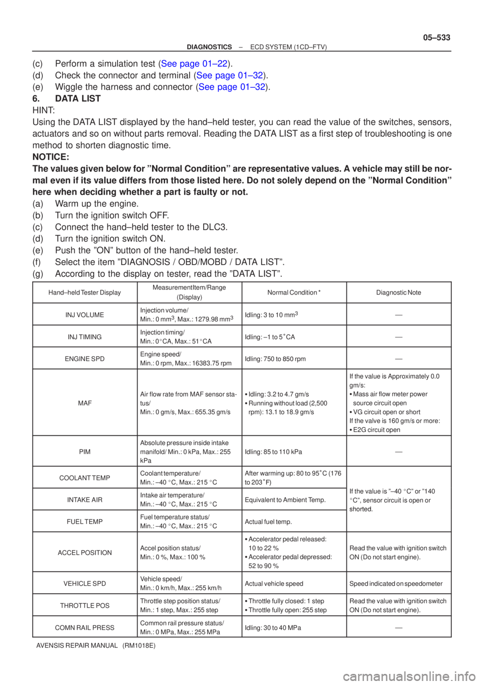
6. DATA LIST
HINT:
Using the DATA LIST displayed by the hand±held tester, you can read the value of the switches, sensors,
actuators and so on without parts removal. Reading the DATA LIST as a first step of troubleshooting is one
method to shorten diagnostic time.
NOTICE:
The values given below for ºNormal Conditionº are representative valu\
es. A vehicle may still be nor-
mal even if its value differs from those listed here. Do not solely depend \
on the ºNormal Conditionº
here when deciding whether a part is faulty or not.
(a) Warm up the engine.
(b) Turn the ignition switch OFF.
(c) Connect the hand±held tester to the DLC3.
(d) Turn the ignition switch ON.
(e) Push the ºONº button of the hand±held tester.
(f) Select the item ºDIAGNOSIS / OBD/MOBD / DATA LISTº.
(g) According to the display on tester, read the ºDATA LISTº.
Hand±held Tester DisplayMeasurement Item/Range
(Display)Normal Condition *Diagnostic Note
INJ VOLUMEInjection volume/
Min.: 0 mm3, Max.: 1279.98 mm3Idling: 3 to 10 mm3�
INJ TIMINGInjection timing/
Min.: 0 �CA, Max.: 51 �CAIdling: ±1 to 5 �CA�
ENGINE SPDEngine speed/
Min.: 0 rpm, Max.: 16383.75 rpmIdling: 750 to ��� rpm�
MAF
Air flow rate from MAF sensor sta-
tus/
Min.: 0 gm/s, Max.: 655.35 gm/s�Idling: 3.2 to 4.7 gm/s
� Running without load (2,500
rpm): 13.1 to 18.9 gm/s
If the value is Approximately 0.0
gm/s:
�Mass air flow meter power
source circuit open
� VG circuit open or short
If the valve is 160 gm/s or more:
� E2G circuit open
PIM
Absolute pressure inside intake
manifold/ Min.: 0 kPa, Max.: 255
kPa
Idling: 85 to 110 kPa�
COOLANT TEMPCoolant temperature/
Min.: ±40 �C, Max.: 215 �CAfter warming up: 80 to 95 �C (176
to 203 ���
INTAKE AIRIntake air temperature/
Min.: ±40 �C, Max.: 215 �CEquivalent to Ambient Temp.
If the value is º±40 �Cº or º140
� Cº, sensor circuit is open or
shorted
FUEL TEMPFuel temperature status/
Min.: ±40 �C, Max.: 215 �CActual fuel temp.
shorted.
ACCEL POSITIONAccel position status/
Min.: 0 %, Max.: 100 %
� Accelerator pedal released:
10 to 22 %
� Accelerator pedal depressed:
52 to 90 %
Read the value with ignition switch
ON (Do not start engine).
VEHICLE SPDVehicle speed/
Min.: 0 km/h, Max.: 255 km/hActual vehicle speedSpeed indicated on speedometer
THROTTLE POSThrottle step position status/
Min.: 1 step, Max.: 255 step�Throttle fully closed: 1 step
� Throttle fully open: 255 stepRead the value with ignition switch
ON (Do not start engine).
COMN RAIL PRESSCommon rail pressure status/
Min.: 0 MPa, Max.: 255 MPaIdling: 30 to 40 MPa�
Page 635 of 5135

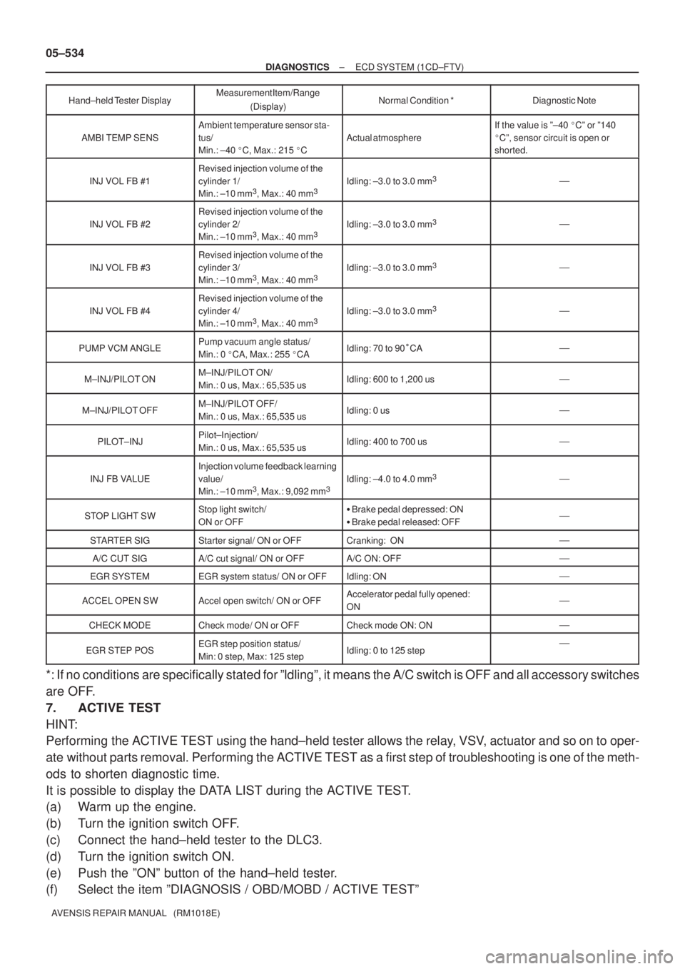
05±534
± DIAGNOSTICSECD SYSTEM (1CD±FTV)
AVENSIS REPAIR MANUAL (RM1018E)Hand±held Tester DisplayDiagnostic Note Normal Condition * Measurement Item/Range
(Display)
AMBI TEMP SENS
Ambient temperature sensor sta-
tus/
Min.: ±40 �C, Max.: 215 �C
Actual atmosphere
If the value is º±40 �Cº or º140
�Cº, sensor circuit is open or
shorted.
INJ VOL FB #1
Revised injection volume of the
cylinder 1/
Min.: ±10 mm
3, Max.: 40 mm3Idling: ±3.0 to 3.0 mm3�
INJ VOL FB #2
Revised injection volume of the
cylinder 2/
Min.: ±10 mm
3, Max.: 40 mm3Idling: ±3.0 to 3.0 mm3�
INJ VOL FB #3
Revised injection volume of the
cylinder 3/
Min.: ±10 mm
3, Max.: 40 mm3Idling: ±3.0 to 3.0 mm3�
INJ VOL FB #4
Revised injection volume of the
cylinder 4/
Min.: ±10 mm
3, Max.: 40 mm3Idling: ±3.0 to 3.0 mm3�
PUMP VCM ANGLEPump vacuum angle status/
Min.: 0 �CA, Max.: 255 �CAIdling: 70 to 90�CA�
M±INJ/PILOT ONM±INJ/PILOT ON/
Min.: 0 us, Max.: 65,535 usIdling: 600 to 1,200 us�
M±INJ/PILOT OFFM±INJ/PILOT OFF/
Min.: 0 us, Max.: 65,535 usIdling: 0 us�
PILOT±INJPilot±Injection/
Min.: 0 us, Max.: 65,535 usIdling: 400 to 700 us�
INJ FB VALUE
Injection volume feedback learning
value/
Min.: ±10 mm
3, Max.: 9,092 mm3Idling: ±4.0 to 4.0 mm3�
STOP LIGHT SWStop light switch/
ON or OFF�Brake pedal depressed: ON
�Brake pedal released: OFF�
STARTER SIGStarter signal/ ON or OFFCranking: ON�
A/C CUT SIGA/C cut signal/ ON or OFFA/C ON: OFF�
EGR SYSTEMEGR system status/ ON or OFFIdling: ON�
ACCEL OPEN SWAccel open switch/ ON or OFFAccelerator pedal fully opened:
ON�
CHECK MODECheck mode/ ON or OFFCheck mode ON: ON�
EGR STEP POSEGR step position status/
Min: 0 step, Max: 125 stepIdling: 0 to 125 step�
*: If no conditions are specifically stated for ºldlingº, it means the A/C switch is OFF and all accessory switches
are OFF.
7. ACTIVE TEST
HINT:
Performing the ACTIVE TEST using the hand±held tester allows the relay, VSV, actuator and so on to oper-
ate without parts removal. Performing the ACTIVE TEST as a first step of troubleshooting is one of the meth-
ods to shorten diagnostic time.
It is possible to display the DATA LIST during the ACTIVE TEST.
(a) Warm up the engine.
(b) Turn the ignition switch OFF.
(c) Connect the hand±held tester to the DLC3.
(d) Turn the ignition switch ON.
(e) Push the ºONº button of the hand±held tester.
(f) Select the item ºDIAGNOSIS / OBD/MOBD / ACTIVE TESTº
Page 778 of 5135
05±726
± DIAGNOSTICSABS WITH EBD SYSTEM
AVENSIS REPAIR MANUAL (RM1018E)
DTC C1241/41 LOW BATTERY POSITIVE VOLTAGE OR
ABNORMALLY HIGH BATTERY POSITIVE
VOLTAGE
CIRCUIT DESCRIPTION
This is the power source of the ECU, hence the actuators.
DTC No.DTC Detecting ConditionTrouble Area
C1241/41
With vehicle speed to about 6 km/h (4 mph), battery voltage
is less than 9.4 V at the time of non±operation of ABS
control or less than 9.2 V at the time of operation of ABS
control, or battery voltage is more than 16.9 V.�Battery
�Charging system
�Power source circuit
050XX±09
Page 779 of 5135
F45133
1 2 33ALT Engine Room R/B No.3
B (*2) W (*2) B±G (*1)
ALT 1
4D 1
1
4B Engine Room J/B No.4 ED1
BatteryFL MAIN
*1: Gasoline
*2: 1CD±FTV
*3: LHD
*4: RHD B±G (*1)
B±L (*2)
1
5918
1 53
2
1
DH DA DB DN
DH
AM1 ECU±IG IG Relay
W±BS21
GND1 GND2
S24
W±BW±B
EA W±B
IJ B (*2) B±G (*1)G±Y R±W
W±B
G±R G±Y G±YR±W R±W
R±W J/C
J10 J20 J10 J20 S2 IG1GC GC 1822
IE1Skid Control ECU
with Actuator
(*3) (*4) (*3) (*4)
I13
Ignition SW
1 3
B±L (*2)
Driver Side J/B
± DIAGNOSTICSABS WITH EBD SYSTEM
05±727
AVENSIS REPAIR MANUAL (RM1018E)
WIRING DIAGRAM
Page 780 of 5135
F45090
Driver Side J/BECU±IG
F45088GNDGNDIG1
05±728
±
DIAGNOSTICS ABS WITH EBD SYSTEM
AVENSIS REPAIR MANUAL (RM1018E)
INSPECTION PROCEDURE
1INSPECT FUSE(ECU±IG FUSE)
(a)Remove the ECU±IG fuse from the driver side J/B.
(b)Check continuity of the ECU±IG fuse. OK:
Continuity
NGINSPECT FOR SHORT CIRCUIT IN ALL HARNESS AND COMPONENTS CONNECTED
TO ECU±IG FUSE
OK
2INSPECT BATTERY
OK:
Voltage: 10 to 14 V NGINSPECT CHARGING SYSTEM
OK
3INSPECT SKID CONTROL ECU CONNECTOR(IG1 TERMINAL VOLTAGE)
IN CASE OF USING HAND±HELD TESTER:
(a)Check the voltage condition, which is output from the ECU and displayed \
on the hand±held tester. OK:
ºNormalº is displayed. IN CASE OF NOT USING HAND±HELD TESTER:
(a)Disconnect the skid control ECU connector.
(b)Turn the ignition switch ON.
(c)Measure the voltage between terminals IG1and GND ofthe skid control ECU harness side connector.
OK:
Voltage: 10 to 14 V
OKREPLACE BRAKE ACTUATOR ASSY (See page 32±54)
NG
Page 782 of 5135
±
DIAGNOSTICS ABS WITH EBD SYSTEM
05±725
AVENSIS REPAIR MANUAL (RM1018E)
DTCC1237/37SPEED SENSOR ROTOR FAULTY
CIRCUIT DESCRIPTION
DTC No.DTC Detecting ConditionTrouble Area
C1237/37
Detection of any of conditions from 1 through 4:
1.Wheel speed deviation of unspecified wheel.
2.Wheel sensor signal failure suspicion.
3.Continuous ABS control for 60 sec. or more.
�Speed sensor
� Sensorrotor
INSPECTION PROCEDURE
1INSPECT TIRE SIZE
NGREPLACE TIRES SO THAT ALL 4 TIRES ARE
SAME IN SIZE
OK
2INSPECT SPEED SENSOR ROTOR
NGREPLACE SENSOR ROTOR
OK
3INSPECT SPEED SENSOR
NGREPLACE SPEED SENSOR
OK
4CHECK HARNESS AND CONNECTOR(SPEED SENSOR ± SKID CONTROL ECU)
(a)Check for an open or short circuit in harness and connector between each term\
inal of speed sensor and the skid control ECU (See page 01±32).
NG REPAIR OR REPLACE HARNESS ORCONNECTOR
OK
REPLACE BRAKE ACTUATOR ASSY(See page 32±54)
0577V±04
Page 783 of 5135
F45132
Battery FL MAINSkid Control ECU
with Actuator
B±G (*1) R (*1)
1 ALT ABS Engine Room R/B No.4 & Engine Room J/B No.4
1
4B
W±BS2
S21 3
+BS
12
1 2
GND1 GND2
S24
W±BW±B
*1: Gasoline
*2: 1CD±FTVEA4
R (*2)
W (*2)
2 12 33 11B1ABS ALT Engine Room R/B No.3Engine Room R/B No.1 &
Engine Room J/B No.1
B (*2)
B±G (*1) 05±722
± DIAGNOSTICSABS WITH EBD SYSTEM
AVENSIS REPAIR MANUAL (RM1018E)
DTC C0278/11 OPEN OR SHORT CIRCUT IN ABS
SOLENOID RELAY
CIRCUIT DESCRIPTION
This relay supplies power to each ABS solenoid. After the ignition switch is turned ON, if the initial check is
OK, the relay goes on.
DTC No.DTC Detecting ConditionTrouble Area
C0278/11
Detection of any conditions from 1 to 3:
1. Internal circuit malfunction in ECU.
2. Valve relay voltage is 0.8 x IG or less for 0.5 sec.
3. Valve relay voltage is high level at valve relay OFF.
�ABS solenoid relay
�ABS solenoid relay circuit
WIRING DIAGRAM
056SS±06
Page 786 of 5135

F45132
Battery FL MAINSkid Control ECU
with Actuator
B±G (*1) L (*1)
1 ALT ABS Engine Room R/B No.4 & Engine Room J/B No.4
1
4B
W±BS2
S21 2
+BM
12
1 2
GND1 GND2
S24
W±BW±B
*1: Gasoline
*2: 1CD±FTVEA4
L (*2)
W (*2)
2 12 33 11B1ABS ALT Engine Room R/B No.3Engine Room R/B No.1 &
Engine Room J/B No.1
B (*2)
B±G (*1)
± DIAGNOSTICSABS WITH EBD SYSTEM
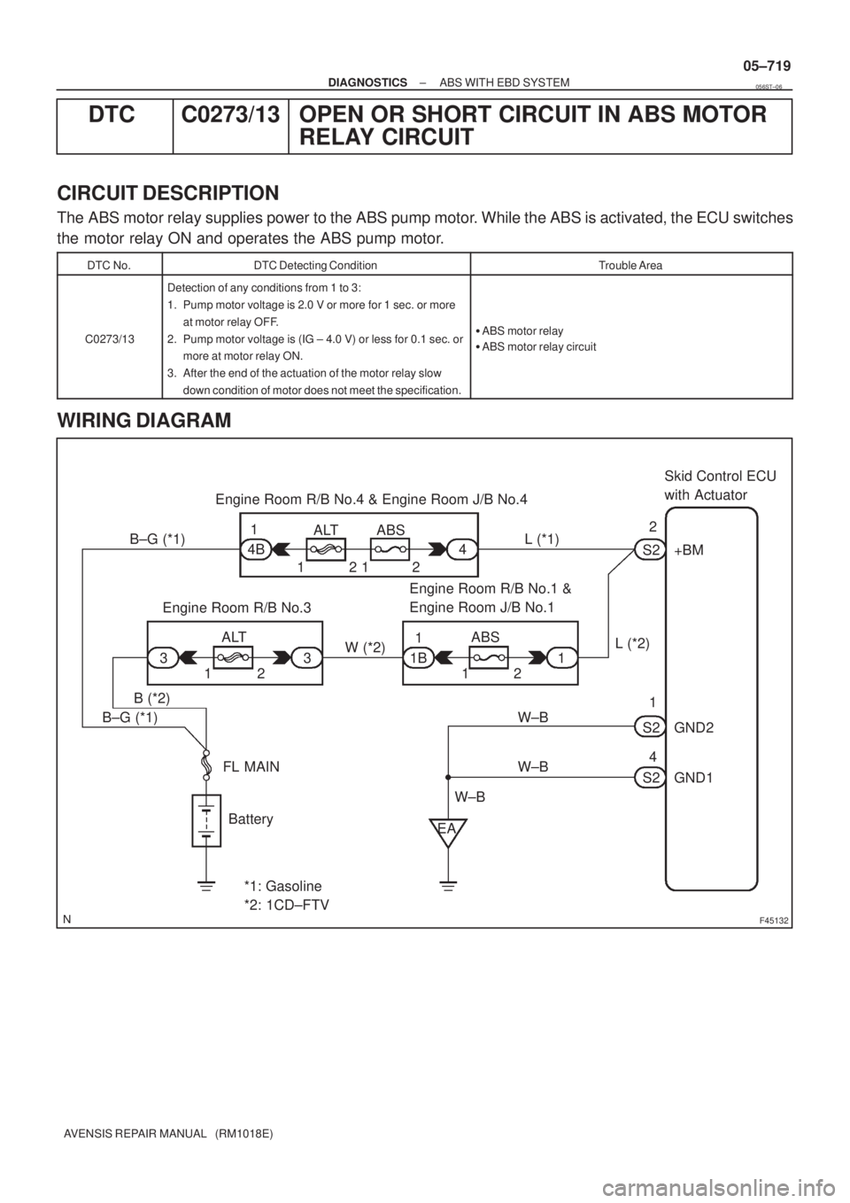
05±719
AVENSIS REPAIR MANUAL (RM1018E)
DTC C0273/13 OPEN OR SHORT CIRCUIT IN ABS MOTOR
RELAY CIRCUIT
CIRCUIT DESCRIPTION
The ABS motor relay supplies power to the ABS pump motor. While the ABS is activated, the ECU switches
the motor relay ON and operates the ABS pump motor.
DTC No.DTC Detecting ConditionTrouble Area
C0273/13
Detection of any conditions from 1 to 3:
1. Pump motor voltage is 2.0 V or more for 1 sec. or more
at motor relay OFF.
2. Pump motor voltage is (IG ± 4.0 V) or less for 0.1 sec. or
more at motor relay ON.
3. After the end of the actuation of the motor relay slow
down condition of motor does not meet the specification.
�ABS motor relay
�ABS motor relay circuit
WIRING DIAGRAM
056ST±06