Page 818 of 5135

05±758
± DIAGNOSTICSABS WITH EBD & BA & TRC & VSC SYSTEM
AVENSIS REPAIR MANUAL (RM1018E)
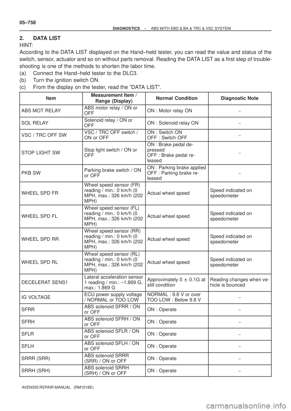
2. DATA LIST
HINT:
According to the DATA LIST displayed on the Hand±held tester, you can read the value and status of the
switch, sensor, actuator and so on without parts removal. Reading the DATA LIST as a first step of trouble-
shooting is one of the methods to shorten the labor time.
(a) Connect the Hand±held tester to the DLC3.
(b) Turn the ignition switch ON.
(c) From the display on the tester, read the ºDATA LISTº.
ItemMeasurement Item /
Range (Display)Normal ConditionDiagnostic Note
ABS MOT RELAYABS motor relay / ON or
OFFON : Motor relay ON±
SOL RELAYSolenoid relay / ON or
OFFON : Solenoid relay ON±
VSC / TRC OFF SWVSC / TRC OFF switch /
ON or OFFON : Switch ON
OFF : Switch OFF±
STOP LIGHT SWStop light switch / ON or
OFF
ON : Brake pedal de-
pressed
OFF : Brake pedal re-
leased
±
PKB SWParking brake switch / ON
or OFFON : Parking brake applied
OFF : Parking brake re-
leased
±
WHEEL SPD FR
Wheel speed sensor (FR)
reading / min.: 0 km/h (0
MPH, max.: 326 km/h (202
MPH)
Actual wheel speedSpeed indicated on
speedometer
WHEEL SPD FL
Wheel speed sensor (FL)
reading / min.: 0 km/h (0
MPH, max.: 326 km/h (202
MPH)
Actual wheel speedSpeed indicated on
speedometer
WHEEL SPD RR
Wheel speed sensor (RR)
reading / min.: 0 km/h (0
MPH, max.: 326 km/h (202
MPH)
Actual wheel speedSpeed indicated on
speedometer
WHEEL SPD RL
Wheel speed sensor (RL)
reading / min.: 0 km/h (0
MPH, max.: 326 km/h (202
MPH)
Actual wheel speedSpeed indicated on
speedometer
DECELERAT SENS1
Lateral acceleration sensor
1 reading / min.: ±1.869 G,
max.: 1.869 GApproximately 0 � 0.1G at
still conditionReading changes when ve-
hicle is bounced
IG VOLTAGEECU power supply voltage
/ NORMAL or TOO LOWNORMAL : 9.8 V or over
TOO LOW : Below 9.8 V±
SFRRABS solenoid SFRR / ON
or OFFON : Operate±
SFRHABS solenoid SFRH / ON
or OFFON : Operate±
SFLRABS solenoid SFLR / ON
or OFFON : Operate±
SFLHABS solenoid SFLH / ON
or OFFON : Operate±
SRRR (SRR)ABS solenoid SRRR
(SRR) / ON or OFFON : Operate±
SRRH (SRH)ABS solenoid SRRH
(SRH) / ON or OFFON : Operate±
Page 820 of 5135

05±760
± DIAGNOSTICSABS WITH EBD & BA & TRC & VSC SYSTEM
AVENSIS REPAIR MANUAL (RM1018E)
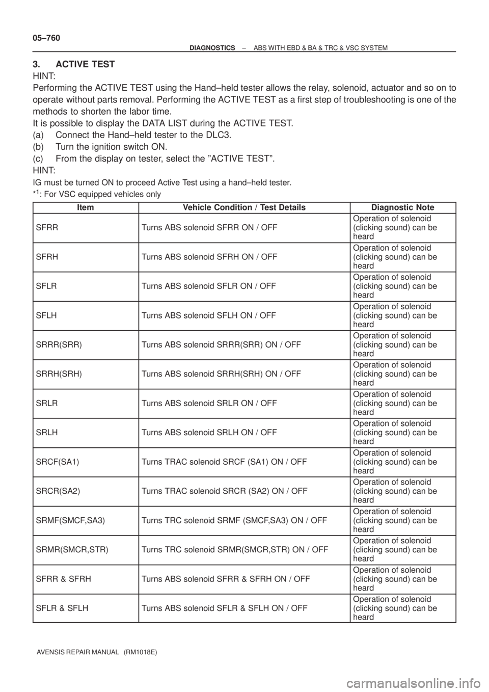
3. ACTIVE TEST
HINT:
Performing the ACTIVE TEST using the Hand±held tester allows the relay, solenoid, actuator and so on to
operate without parts removal. Performing the ACTIVE TEST as a first step of troubleshooting is one of the
methods to shorten the labor time.
It is possible to display the DATA LIST during the ACTIVE TEST.
(a) Connect the Hand±held tester to the DLC3.
(b) Turn the ignition switch ON.
(c) From the display on tester, select the ºACTIVE TESTº.
HINT:
IG must be turned ON to proceed Active Test using a hand±held tester.
*
1: For VSC equipped vehicles only
Item
Vehicle Condition / Test DetailsDiagnostic Note
SFRRTurns ABS solenoid SFRR ON / OFF
Operation of solenoid
(clicking sound) can be
heard
SFRHTurns ABS solenoid SFRH ON / OFF
Operation of solenoid
(clicking sound) can be
heard
SFLRTurns ABS solenoid SFLR ON / OFF
Operation of solenoid
(clicking sound) can be
heard
SFLHTurns ABS solenoid SFLH ON / OFF
Operation of solenoid
(clicking sound) can be
heard
SRRR(SRR)Turns ABS solenoid SRRR(SRR) ON / OFF
Operation of solenoid
(clicking sound) can be
heard
SRRH(SRH)Turns ABS solenoid SRRH(SRH) ON / OFF
Operation of solenoid
(clicking sound) can be
heard
SRLRTurns ABS solenoid SRLR ON / OFF
Operation of solenoid
(clicking sound) can be
heard
SRLHTurns ABS solenoid SRLH ON / OFF
Operation of solenoid
(clicking sound) can be
heard
SRCF(SA1)Turns TRAC solenoid SRCF (SA1) ON / OFF
Operation of solenoid
(clicking sound) can be
heard
SRCR(SA2)Turns TRAC solenoid SRCR (SA2) ON / OFF
Operation of solenoid
(clicking sound) can be
heard
SRMF(SMCF,SA3)Turns TRC solenoid SRMF (SMCF,SA3) ON / OFF
Operation of solenoid
(clicking sound) can be
heard
SRMR(SMCR,STR)Turns TRC solenoid SRMR(SMCR,STR) ON / OFF
Operation of solenoid
(clicking sound) can be
heard
SFRR & SFRHTurns ABS solenoid SFRR & SFRH ON / OFF
Operation of solenoid
(clicking sound) can be
heard
SFLR & SFLHTurns ABS solenoid SFLR & SFLH ON / OFF
Operation of solenoid
(clicking sound) can be
heard
Page 830 of 5135
F45137
Skid Control ECU
with Actuator
W±B (*1) W±B (*1)W±B (*2)W (*2) W (*1) W (*1) W
S2 TS13
W±B (*2)
CB CA6 3IE2 12 J8
J/C
D
A
IO IP CG TS D5
DLC3 1AZ±FE:
4 12
D
ACenter J/B
J16
J/C
*1: LHD
*2: RHD
C87489
Skid Control ECU
with Actuator
W±B (*1) W±B (*1)W±B (*2) W (*2)W (*1) W (*1) W
S2 TS13
W±B (*2)
CB CA6 3IE2 12 J8
J/C
D
A
IP CG TS D5
DLC3 Except 1AZ±FE:
4 12 D
ACenter J/B
J16
J/C
*1: LHD
*2: RHDIO: Gasoline
IL: 1CD±FTV D
B
J20 J21W (*2) J/C
05±750
± DIAGNOSTICSABS WITH EBD SYSTEM
AVENSIS REPAIR MANUAL (RM1018E)
TS TERMINAL CIRCUIT
CIRCUIT DESCRIPTION
The sensor check circuit detects troubles in the sensor signal which cannot be detected by the DTC check.
Connecting terminals Ts and CG of the DLC3 starts the check.
WIRING DIAGRAM
05C5D±01
Page 831 of 5135
C52361
Ts
CGDLC3
−
DIAGNOSTICS ABS WITH EBD SYSTEM
05−751
INSPECTION PROCEDURE
1 INSPECT DLC3 TERMINAL VOLTAGE(Ts TERMINAL)
(a) Turn the ignition switch ON.
(b) Measure the voltage between terminals Ts and CG of the
DLC3.
OK:
Voltage: 10 to 14 V
OK Go to step 3
NG
2 CHECK HARNESS AND CONNECTOR(DLC3 −BODY GROUND)
(a) Check for an open or short circuit in harness and connector between terminal Ts of the DLC3 and the
skid control ECU (See page 01− 32).
NG REPAIR OR REPLACE HARNESS ORCONNECTOR
OK
3 CHECK AND REPAIR HARNESS AND CONNECTOR(SKID CONTROL ECU −DLC3)
(a) Check for an open or short circuit in harness and connector between terminal CG of the DLC3 and body
ground (See page 01− 32).
NG REPAIR OR REPLACE HARNESS ORCONNECTOR
OK
REPLACE BRAKE ACTUATOR ASSY(See page 32− 54)
Page 832 of 5135
F45136
Skid Control ECU
with Actuator
S225 D5
DLC3
TC
CG13
4
W±B (*1) W±L (*1)
AA BB
W±B (*2)J8
J/C
W±L (*1) W±L (*2)
W±B (*1) J16
J/C
IO IPCB3
CA6 DL15
DB17Driver Side J/B
Center J/B
W±B (*2)W±L
*1: LHD
*2: RHDTC 1AZ±FE:
C87490
Skid Control ECU
with Actuator
S225 D5 DLC3
TC
CG13
4
W±B (*1) W±L (*1)
AA BB
W±B (*2)J/C
W±L (*1) W±L (*2)
W±B (*1) J16
J/C
IP CB3
CA6 DL15
DB17Driver Side J/B
Center J/B
W±B (*2)W±L
*1: LHD
*2: RHDTC Except 1AZ±FE:
W±L (*2) B
J8
J/C D
J21 J20
IO: Gasoline
IL: 1CD±FTV
05±748
± DIAGNOSTICSABS WITH EBD SYSTEM
AVENSIS REPAIR MANUAL (RM1018E)
TC TERMINAL CIRCUIT
CIRCUIT DESCRIPTION
Connecting terminals Tc and CG of the DLC3 causes the ECU to display the DTC by flashing the ABS warn-
ing light.
WIRING DIAGRAM
05C5C±01
Page 833 of 5135
C52361
TcCGDLC3
±
DIAGNOSTICS ABS WITH EBD SYSTEM
05±749
AVENSIS REPAIR MANUAL (RM1018E)
INSPECTION PROCEDURE
1INSPECT DLC3 TERMINAL VOLTAGE(Tc TERMINAL)
(a)Turn the ignition switch ON.
(b)Measure the voltage between terminals Tc and CG of the
DLC3.
OK:
Voltage: 10 to 14 V
OKGo to step 3
NG
2CHECK HARNESS AND CONNECTOR(DLC3 ± BODY GROUND)
(a)Check for an open or short circuit in harness and connector between terminal \
CG of the DLC3 and body ground (See page 01±32).
NG REPAIR OR REPLACE HARNESS ORCONNECTOR
OK
3 CHECK HARNESS AND CONNECTOR(SKID CONTROL ECU ± DLC3)
(a) Check for an open or short circuit in harness and connector between term\
inal Tc of the skid control ECU and the DLC3 (See page 01±32).
NG REPAIR OR REPLACE HARNESS ORCONNECTOR
OK
REPLACE BRAKE ACTUATOR ASSY(See page 32±54)
Page 835 of 5135
F45135
B±R
DH DA18 2Driver Side J/B
IGNEBDW S212
IE118 4
B±W
C11 C11Combination Meter
BrakeSkid Control ECU
with Actuator
P P 22
17
C10
AM2
4B 4A11IG2
A 1
2 AM2
3
IK 1A
Engine Room R/B No.3 Engine Room R/B No.1 & Engine Room J/B No.1
1
3 Engine Room J/B No.41
IO ILJ15
J/C
Battery
*1: Gasoline
*2: 1CD±FTV
*3: LHD
*4: RHD(*3) (*4) (*3) (*4)B±W CA CA
J8 J26 J8 J26J/C
B±R
IE4 IP111
(*3) (*4) B±R
B (*2)B±G (*1)
B (*2)
FL MAINB±G (*1)
W±B (*3 *2)
W±B (*3 *1)A A
AAJ17
J/C
J16
J/C W±B
(*3) W±B (*4)
W±B (*4)
I13
Ignition SW
46
± DIAGNOSTICSABS WITH EBD SYSTEM
05±745
AVENSIS REPAIR MANUAL (RM1018E)
WIRING DIAGRAM
Page 837 of 5135
±
DIAGNOSTICS ABS WITH EBD SYSTEM
05±747
AVENSIS REPAIR MANUAL (RM1018E)
6 CHECK HARNESS AND CONNECTOR(BRAKE ACTUATOR ± COMBINATION
METER)
(a) Check for an open or short circuit in harness and connector between the brake\
actuator and combina-
tion meter (See page 01±32).
NG REPAIR OR REPLACE HARNESS ORCONNECTOR
OK
REPLACE BRAKE ACTUATOR ASSY(See page 32±54)