Page 2614 of 5135

32±53
AVENSIS REPAIR MANUAL (RM1018E)
BRAKE ACTUATOR ASSY (W/O VSC)
ON±VEHICLE INSPECTION
1. CONNECT HAND±HELD TESTER:
(a) Connect the hand�")
320VY±01
F45949
± BRAKEBRAKE ACTUATOR ASSY (W/O VSC)
32±53
AVENSIS REPAIR MANUAL (RM1018E)
BRAKE ACTUATOR ASSY (W/O VSC)
ON±VEHICLE INSPECTION
1. CONNECT HAND±HELD TESTER:
(a) Connect the hand±held tester to the DLC3.
(b) Start the engine and run at idle.
(c) Select the ACTIVE TEST mode on the hand±held tester.
HINT:
Please refer to the hand±held tester operator's manual for fur-
ther details.
2. INSPECT ACTUATOR MOTOR OPERATION
(a) With the motor relay on, check the actuator motor operation noise.
(b) Turn the motor relay off.
(c) Depress the brake pedal and hold it for about 15 seconds. Check that the brake pedal cannot be de-
pressed.
(d) With the motor relay on, check that the pedal does not pulsate.
NOTICE:
Do not keep a motor relay tvrned on for more than 5 seconds continuously. When operating it contin-
uously, set an interval more than 20 seconds.
(e) Turn the motor relay off and release the brake pedal.
3. INSPECT RIGHT FRONT WHEEL OPERATION
NOTICE:
Never turn on a solenoid in a manner described below.
(a) With the brake pedal depressed, perform the following operations.
(b) Turn the SFRH and SFRR solenoid on simultaneously, and check that the pedal cannot be depressed.
NOTICE:
Do not keep a solenoids tvrned on for more than 5 seconds continuously. When operating it continu-
ously, set an interval more than 20 seconds.
(c) Turn the SFRH and SFRR solenoid off simultaneously, and check that the pedal can be depressed.
(d) Turn the motor relay on, and check that the pedal returns.
NOTICE:
Do not keep a motor relay tvrned on for more than 5 seconds continuously. When operating it contin-
uously, set an interval more than 20 seconds.
(e) Turn the motor relay off and release the brake pedal.
4. INSPECT OTHER WHEEL OPERATION
(a) Using the same procedure, check the solenoids of the other wheels.
HINT:
Left front wheel: SFLH, SFLR
Right rear wheel: SRRH, SRRR
Left rear wheel: SRLH, SRLR
Page 2635 of 5135

32±25
AVENSIS REPAIR MANUAL (RM1018E)
REPLACEMENT
NOTICE:
Do not adjust the brake booster push rod.
1. DRAIN BRAKE FLUID
NOTICE:
Wash the b")
320W4±01
G24211
F42291
±
BRAKE BRAKE BOOSTER ASSY (RHD)
32±25
AVENSIS REPAIR MANUAL (RM1018E)
REPLACEMENT
NOTICE:
Do not adjust the brake booster push rod.
1. DRAIN BRAKE FLUID
NOTICE:
Wash the brake fluid off immediately if it adheres to any painted surface\
.
2.REMOVE BRAKE MASTER CYLINDER SUB±ASSY (See page 32±13)
(a) w/o VSC:
SST 09023±00100
(b) w/ VSC: SST 09023±38400
3.REMOVE CLUTCH MASTER CYLINDER ASSY (M/T TRANSAXLE) (See page 42±13) SST 09023±00100
4. REMOVE ENGINE ASSEMBLY WITH TRANSAXLE (1AZ±FSE ENGINE TYPE) (See page 14±204)
5. REMOVE ENGINE COVER NO.1
6.REMOVE IGNITION COIL ASSY (GASOLINE ENGINE TYPE) (See page 14±81)
7.REMOVE CYLINDER HEAD COVER SUB±ASSY (GASOLINE ENGINE TYPE) (See page 14±81)
8.REMOVE TIMING BELT NO.2 COVER (DIESEL ENGINE TYPE) (See page 14±307)
9.REMOVE CYLINDER HEAD COVER SUB±ASSY (DIESEL ENGINE TYPE) (See page 14±318)
10.REMOVE INJECTOR ASSY (DIESEL ENGINE TYPE) (See page 14±318)
11. REMOVE FRONT WHEEL RH
12. REMOVE BRAKE TUBE
(a) w/o VSC:Using SST, disconnect the 6 brake tubes from the brake
actuator.
SST 09023±00100
(b) w/ VSC: Using SST, disconnect the 6 brake tubes from the brake
actuator.
SST 09023±00100, 09023±38400
Page 3050 of 5135

2. INSPECT HEADLAMP ASSEMBLY (HEADLIGHT
BEAM LEVEL CONTROL ACTUATOR OPERATION)
(a) Disconnect t")
E68999
LH:
RH: 1
13
3 2
2
1
25
E68130
65±6
± LIGHTINGLIGHTING SYSTEM
AVENSIS REPAIR MANUAL (RM1018E)
2. INSPECT HEADLAMP ASSEMBLY (HEADLIGHT
BEAM LEVEL CONTROL ACTUATOR OPERATION)
(a) Disconnect the connector from the headlamp assy.
(b) Connect the positive (+) lead from the battery to the termi-
nal 3 of each of the headlight beam level control actuator
and negative (±) lead from the battery to the terminal 1 of
the each of the headlight beam level control actuator.
(c) Connect the positive (+) lead from the battery to the termi-
nal 1 of headlamp levering switch and negative (±) lead
from the battery to the terminal 5 of the headlamp levering
switch.
(d) Connect the terminal 2 of the headlamp leveling switch
and the terminal 2 of the each of headlight beam level
control actuator.
(e) Measure voltage between the terminal 2 of the headlamp
leveling switch and the battery negative (±) terminal when
headlamp levering switch is operated.
Standard:
Switch positionSpecified condition (V)
08.5 to 11.8
17.4 to 10.3
26.3 to 8.8
35.2 to 7.3
44.1 to 5.8
53.0 to 4.3
3. HEADLAMP LEVELING ECU ASSY
(a) Measure voltage between the terminal as shown in the
chart below.
Standard:
Tester connectionConditionSpecified condition
1 ± body groundTurn ignition switch ON10 to 14 V
1 ± body groundTurn ignition switch OFFNo voltage
10 ± body groundHeadlamp switch is HEADBelow 1 V
24 ± body groundAlwaysContinuity
Page 3054 of 5135

3. TURN SIGNAL AND HAZARD WARNING SYSTEM
SymptomSuspect AreaSee page
ºHazardº and ºTurnº do not come on.
1. HAZARD fuse
2. GAUGE")
±
LIGHTING LIGHTING SYSTEM
65±3
AVENSIS REPAIR MANUAL (RM1018E)
3. TURN SIGNAL AND HAZARD WARNING SYSTEM
SymptomSuspect AreaSee page
ºHazardº and ºTurnº do not come on.
1. HAZARD fuse
2. GAUGE2 fuse
3. IG1 relay
4. Ignition switch
5. Turn signal flasher relay
6. Harness or connector±
±
±
±
65±5
±
Hazard warning light does not come on.
(Turn is normal)1. Hazard warning switch
2. Harness or connector65±9±
Turn signal does not come on.
(Hazard is normal)1. Headlamp dimmer switch (turn signal switch)
2. Harness or connector65±9±
Turn signal does not come on in one direction.1. Headlamp dimmer switch (turn signal switch)
2. Harness or connector65±9±
Only one bulb does not come on.1. Bulb
2. Harness or connector±
±
4. ILLUMINATED ENTRY SYSTEM
SymptomSuspect AreaSee page
Illumination lamp of Multiplex body ECU control does not come
on.
1. Ignition switch
2. Door courtesy switch
3. Door lock position switch
4. Harness or connector
5. Integration relay±
65±9
05±1534 ±
±
Illumination lamp of Multiplex body ECU control does not go off.
1. Ignition switch
2. Door courtesy switch
3. Door lock position switch
4. Harness or connector
5. Integration relay±
65±9
05±1534 ±
±
5. HEADLIGHT BEAM LEVEL CONTROL SYSTEM (W/O HID)
SymptomSuspect AreaSee page
Headlight beam level control system does not operate (All).
1. TAIL relay
2. Headlamp leveling switch
3. Harness or connector±
65±9 ±
Headlight beam level control system does not operate (One side).
1. Headlamp leveling switch
2. Headlight beam level control actuator
3. Harness or connector65±9
65±5±
6. HEADLIGHT BEAM LEVEL CONTROL SYSTEM (W/ HID)
SymptomSuspect AreaSee page
Headlight beam level control system does not operate (All).
1. GAUGE2 fuse
2. Ignition switch
3. Speed sensor signal circuit
4. Height control sensor sub±assy
5. Headlamp leveling ECU assy
6. Harness or connector±
±
±
65±9
65±5 ±
Headlight beam level control system does not operate (One side).
1. Headlamp leveling ECU assy
2. Headlight beam level control actuator
3. Harness or connector65±5
65±5±
Beam level warning light comes on.
1. Height control sensor sub±assy
2. Headlamp leveling ECU assy
3. Harness or connector65±9
65±5±
Page 3135 of 5135
660CS±01
������E68351
I35261
������
E68352
±
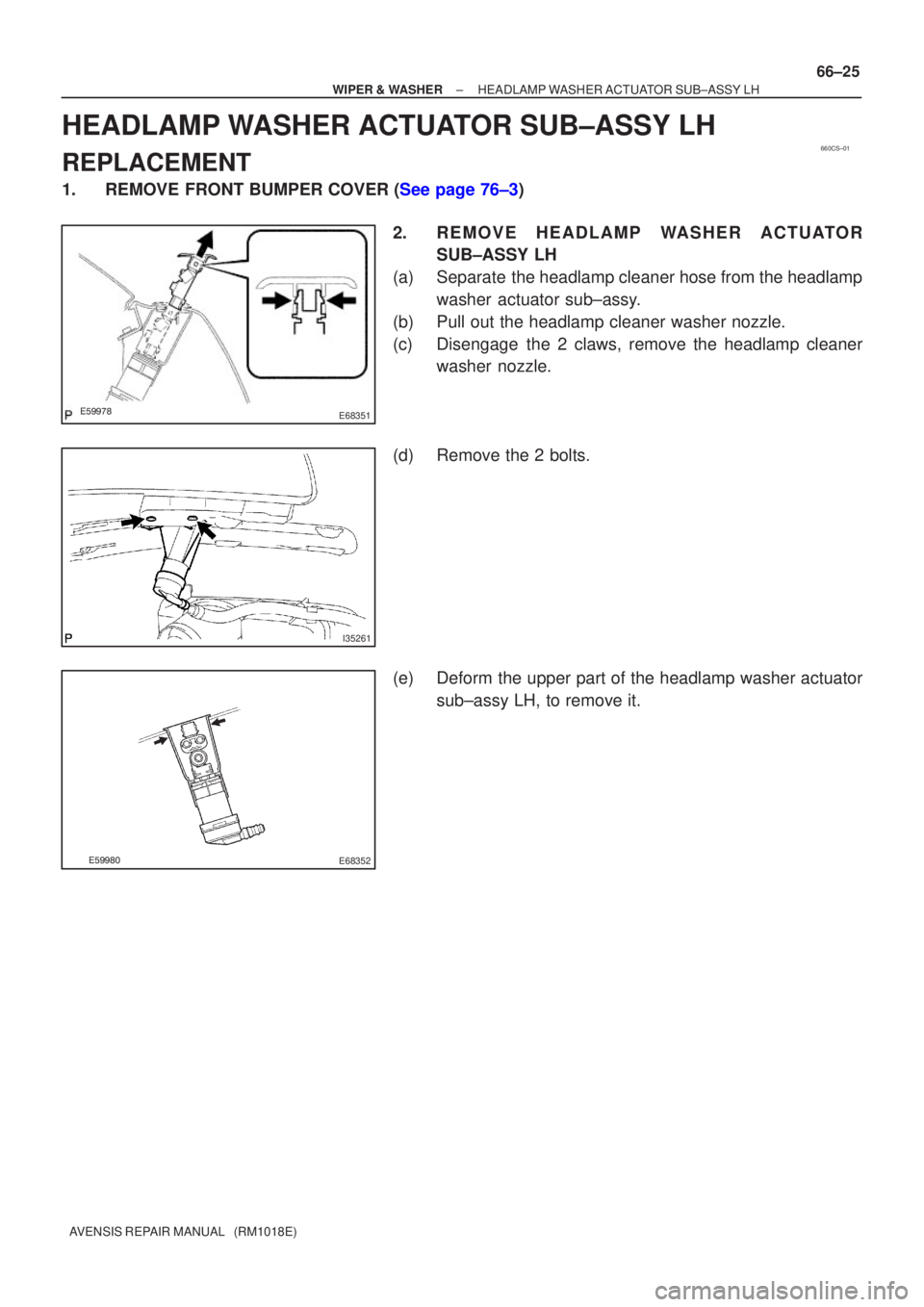
WIPER & WASHER HEADLAMP WASHER ACTUATOR SUB±ASSY LH
66±25
AVENSIS REPAIR MANUAL (RM1018E)
HEADLAMP WASHER ACTUATOR SUB±ASSY LH
REPLACEMENT
1.REMOVE FRONT BUMPER COVER (See page 76±3)
2. R E M O V E H E A D L A M P WA S H E R A C T U ATO RSUB±ASSY LH
(a) Separate the headlamp cleaner hose from the headlamp washer actuator sub±assy.
(b) Pull out the headlamp cleaner washer nozzle.
(c) Disengage the 2 claws, remove the headlamp cleaner washer nozzle.
(d) Remove the 2 bolts.
(e) Deform the upper part of the headlamp washer actuator sub±assy LH, to remove it.
Page 3393 of 5135

REPLACEMENT
HINT:
The installation is in the reverse order of the removal. However, when ther")
760WY±01
B67425
Claw
B67431
± EXTERIOR/INTERIOR TRIMFRONT BUMPER
76±3
AVENSIS REPAIR MANUAL (RM1018E)
REPLACEMENT
HINT:
The installation is in the reverse order of the removal. However, when there is a special point concerning
the installation, it is indicated.
1. REMOVE FRONT BUMPER COVER
(a) Put protective tape under the front fender.
HINT:
Because the spoiler covers LH and RH are assembled, remove
them together.
(b) Remove the spoiler.
(1) Remove the 9 screws and 6 claws.
(2) Remove the 6 retainers.
(3) Remove the spoiler covers LH and RH together.
(4) Remove the bolt and separate the spoiler cover RH
from the LH.
(c) Remove the 3 bolts and 2 clips.
(d) Using a screwdriver, disengage the 6 claws and remove
the bumper cover.
HINT:
Tape the screwdriver tip before use.
(e) w/ Fog lamp:
Disconnect the fog lamp connectors.
2. R E M O V E H E A D L A M P WA S H E R A C T U ATO R
SUB±ASSY LH (W/ HEADLAMP CLEANER)
(a) Remove the washer hose clip.
(b) Using a screwdriver, pry out the front washer nozzle.
HINT:
Tape the screwdriver tip before use.
(c) Remove the 2 screws and actuator.
3. REMOVE HEADLAMP WASHER ACTUATOR SUB±ASSY RH (W/ HEADLAMP CLEANER)
HINT:
Use the same procedures described for the LH side.
4. REMOVE INTERCOOLER COOLING AIR DUCT SUB±ASSY (W/ CAC 1CD±FTV ENGINE TYPE)
(a) Remove the 3 screws and air duct.
5. REMOVE FRONT BUMPER REINFORCEMENT SUB±ASSY
(a) Using a screwdriver, remove the wire harness.
(b) Remove the 8 bolts and reinforcement.
6. REMOVE FRONT BUMPER SIDE RETAINER LH
(a) Using a screwdriver, remove the 2 screws and retainer.
HINT:
Tape the screwdriver tip before use.
Page 3396 of 5135
B68229
w/ Headlamp Cleaner
Headlamp Washer
Actuator Sub±assy RH
Headlamp Washer
Actuator Sub±assy LH
Radiator Grille Lower
Front Bumper Cover Headlamp Washer
Nozzle Sub±assy LH Headlamp Washer
Nozzle Sub±assy RH
Front Spoiler
Cover LH Front Spoiler
Cover RH
76±2
± EXTERIOR/INTERIOR TRIMFRONT BUMPER
AVENSIS REPAIR MANUAL (RM1018E)
Page 3807 of 5135
030KT±01
± SERVICE SPECIFICATIONSINTAKE
03±5
1CD±FTV ENGINE REPAIR MANUAL (RM927E)
TORQUE SPECIFICATION
Part tightenedN´mkgf´cmft´lbf
V Band8.38574 in.´lbf
Compressor housing x Bearing housing4.74842 in.´lbf
Turbocharger actuator x Compressor housing7.88069 in.´lbf
Compressor inlet elbow x Compressor housing2323517


TORQUE SPECIFICATION
Part tightenedN´mkgf´cmft´lbf
V Band8.38574 in.´lbf
Compressor housing x Bearing housi")