Page 2005 of 5135

13±3
AVENSIS REPAIR MANUAL (RM1018E)
TURBO CHARGER SYSTEM (1CD±FTV)
PRECAUTION
1. MAINTENANCE PRECAUTION
(a) Do not stop the")
1302Y±03
A77119
A77120
A77121
± INTAKETURBO CHARGER SYSTEM (1CD±FTV)
13±3
AVENSIS REPAIR MANUAL (RM1018E)
TURBO CHARGER SYSTEM (1CD±FTV)
PRECAUTION
1. MAINTENANCE PRECAUTION
(a) Do not stop the engine immediately after pulling a trailer,
or after driving at a high speed, or uphill drive. Let the en-
gine Idle for 20 to 120 seconds before turn the ignition
switch OFF (According as the driving condition, the idling
time varies).
(b) Avoid quick acceleration or quickly accelerating the en-
gine RPM immediately after the starting a cold engine.
(c) If the turbocharger is found to be defective, it must be re-
placed. Also, inspect a source of the trouble including
conditions of the turbocharger that having been used. Re-
pair or replace the followings as necessary:
(1) Engine oil (Level and quality)
(2) Oil lines leading to the turbocharger
(d) Pay due attention when removing and reinstalling the
turbocharger assembly. Do not drop, or do not give shock,
or do not grasp easily±deformed assembly parts such as
the actuator or push rod in removal and reinstallation.
(e) Before removal, cover both the intake and exhaust ports
and the oil inlet to prevent dirt or foreign objects from be-
ing introduced.
(f) If replacing the turbocharger, check for deposits in the oil
pipe. If necessary, replace the oil pipe too.
(g) Thoroughly remove old gasket sticking to the lubrication
oil pipe flange and the turbocharger oil flange.
(h) If replacing the bolt(s) or nut(s), must use Toyota genuine
parts to prevent breakage or deformation.
(i) If replacing the turbocharger, put 20 cm
3 (1.2 cu in.) of
fresh oil into the turbocharger oil inlet hole and turn the tur-
bine wheel by hand to spread oil to the bearing.
(j) If overhauling or replacing the engine, cut the fuel supply
after reassembly and crank the engine for 30 seconds to
feed oil throughout the engine then run the engine at idle
for 60 seconds.
Page 2007 of 5135
1306S±02
A79032
Filter
AB
A59586
13±2
± INTAKEINTAKE AIR CONTROL SYSTEM (1AZ±FSE)
AVENSIS REPAIR MANUAL (RM1018E)
INSPECTION
1. INSPECT INTAKE AIR CONTROL VALVE ASSY
(a) With 34.7 kPa (260 mm Hg, 10.2 in. Hg) of vacuum ap-
plied to the actuator, check that the actuator rod moves.
(b) One minute after applying the vacuum, check that the ac-
tuator rod does not return.
(c) If the operation is not as specified, replace the intake air
control valve assembly.
NOTICE:
Do not touch the adjust screw.
2. INSPECT VACUUM SWITCHING VALVE ASSY NO.1
(a) Using an ohmmeter, measure resistance between each
terminal.
Resistance: 33 to 39 � at 20�C (68�F)
(b) Check that air flows form port B to the filter.
(c) Apply battery voltage across the terminals.
(d) Check that air flows from port B to port A.
Page 2008 of 5135
1302G±03
A77131
Vacuum Gage
35.7
�
3700 100
Throttle Valve Open Position
���
Engine Speed [r/min.]ON
OFF
A59594
SCV VSV
± INTAKEINTAKE AIR CONTROL SYSTEM (1AZ±FSE)
13±1
AVENSIS REPAIR MANUAL (RM1018E)
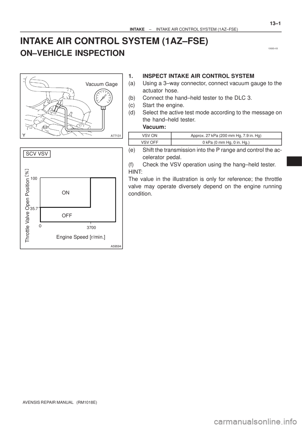
INTAKE AIR CONTROL SYSTEM (1AZ±FSE)
ON±VEHICLE INSPECTION
1. INSPECT INTAKE AIR CONTROL SYSTEM
(a) Using a 3±way connector, connect vacuum gauge to the
actuator hose.
(b) Connect the hand±held tester to the DLC 3.
(c) Start the engine.
(d) Select the active test mode according to the message on
the hand±held tester.
Vacuum:
VSV ONApprox. 27 kPa (200 mm Hg, 7.9 in. Hg)
VSV OFF0 kPa (0 mm Hg, 0 in. Hg.)
(e) Shift the transmission into the P range and control the ac-
celerator pedal.
(f) Check the VSV operation using the hang±held tester.
HINT:
The value in the illustration is only for reference; the throttle
valve may operate diversely depend on the engine running
condition.
Page 2609 of 5135
320VX±01
F42291
F42290
To
Master
Cylinder
FrontTo Master
Cylinder
Rear
To Rear
Wheel RH
To Front Wheel LHTo Front Wheel RH
To Rear
Wheel LH
F42292
± BRAKEBRAKE ACTUATOR ASSY (W/ VSC)
32±57
AVENSIS REPAIR MANUAL (RM1018E)
REPLACEMENT
1. DRAIN BRAKE FLUID
NOTICE:
Wash the brake fluid off immediately if it adheres to any painted surfaces.
2. REMOVE FRONT WHEEL RH
3. REMOVE FRONT FENDER LINER RH
4. REMOVE BRAKE ACTUATOR WITH BRACKET
(a) Release the latch of the brake actuator connector to dis-
connect the connector.
(b) Disconnect oil presser sensor connector.
(c) Using SST, disconnect the brake tubes from the brake ac-
tuator.
SST 09023±00100, 09023±38400
(d) Use tags or make a memo to identify the place to recon-
nect.
(e) Remove the nut, 2 bolts and brake actuator with bracket.
Page 2610 of 5135

AVENSIS REPAIR")
F42292
F42290
To
Master
Cylinder
FrontTo Master
Cylinder
Rear
To Rear
Wheel RH
To Front Wheel LHTo Front Wheel RH
To Rear
Wheel LH
AA
A
A
BB
32±58
±
BRAKE BRAKE ACTUATOR ASSY (W/ VSC)
AVENSIS REPAIR MANUAL (RM1018E)
5. REMOVE BRAKE ACTUATOR ASSY
(a) Remove the 3 bolts and brake actuator from the brake acutuator bracket.
6. REMOVE OIL PRESSURE SENSOR
7. REMOVE SKID CONTROL ECU
(a) Disconnect the connector from the skid control ECU.
(b) Using a torx driver (T20), remove the 6 screws and the skid control EC\
U from the brake actuator.
8. INSTALL SKID CONTROL ECU
(a) Install the skid control ECU and 6 screws with a torx driver (T20).
(b) Connect the connector to the skid control ECU.
9. INSTALL OIL PRESSURE SENSOR
10. INSTALL BRAKE ACTUATOR ASSY
(a) Install the brake actuator with 3 the bolts to the brake actuator bracke\
t. Torque: 4.7 N �m (48 kgf �cm, 42 in. �lbf)
11. INSTALL BRAKE ACTUATOR WITH BRACKET
(a) Install the brake actuator with bracket with the nut and 2 bolts.
Torque: 19 N �m (194 kgf �cm, 14 ft �lbf)
(b) Using SST, connect each brake line to the correct position of the brake actuator, as shown in the illustration.
SST 09023±00100, 09023±38400
Torque:
A: 15 N �m (155 kgf �cm, 11 ft �lbf)
B: 29 N �m (296 kgf �cm, 21 ft �lbf)
(c) Connect the oil presser sensor connector.
(d) Connect the brake actuator connector.
12. INSTALL FRONT FENDER LINER RH
13. INSTALL FRONT WHEEL RH Torque: 103 N �m (1,050 kgf �cm, 76 ft �lbf)
14.FILL RESERVOIR WITH BRAKE FLUID (See page 32±4)
15.BLEED MASTER CYLINDER (See page 32±4) SST 09023±38400
16.BLEED BRAKE LINE (See page 32±4)
17.CHECK FLUID LEVEL IN RESERVOIR (See page 32±4)
18. CHECK BRAKE FLUID LEAKAGE
19.CHECK BRAKE ACTUATOR WITH HAND±HELD TESTER (See page 05±756)
Page 2611 of 5135

AVENSIS REPAIR MANUAL (RM1018E)
BRAKE ACTUATOR ASSY (W/ VSC)
ON±VEHICLE INSPECTION
1. CONNECT HAND±HELD TESTER:
(a) Connect the hand±h")
320VW±01
F45949
32±56
± BRAKEBRAKE ACTUATOR ASSY (W/ VSC)
AVENSIS REPAIR MANUAL (RM1018E)
BRAKE ACTUATOR ASSY (W/ VSC)
ON±VEHICLE INSPECTION
1. CONNECT HAND±HELD TESTER:
(a) Connect the hand±held tester to the DLC3.
(b) Start the engine and run at idle.
(c) Select the ACTIVE TEST mode on the hand±held tester.
HINT:
Please refer to the hand±held tester operator's manual for fur-
ther details.
2. INSPECT ACTUATOR MOTOR OPERATION
(a) With the motor relay on, check the actuator motor operation noise.
(b) Turn the motor relay off.
(c) Depress the brake pedal and hold it for about 15 seconds. Check that the brake pedal cannot be de-
pressed.
(d) With the motor relay on, check that the pedal does not pulsate.
NOTICE:
Do not keep a motor relay tvrned on for more than 5 seconds continuously. When operating it contin-
uously, set an interval more than 20 seconds.
(e) Turn the motor relay off and release the brake pedal.
3. INSPECT RIGHT FRONT WHEEL OPERATION
NOTICE:
Never turn on a solenoid in a manner described below.
(a) With the brake pedal depressed, perform the following operations.
(b) Turn the SFRH and SFRR solenoid on simultaneously, and check that the pedal cannot be depressed.
NOTICE:
Do not keep a solenoids tvrned on for more than 5 seconds continuously. When operating it continu-
ously, set an interval more than 20 seconds.
(c) Turn the SFRH and SFRR solenoid off simultaneously, and check that the pedal can be depressed.
(d) Turn the motor relay on, and check that the pedal returns.
NOTICE:
Do not keep a motor relay tvrned on for more than 5 seconds continuously. When operating it contin-
uously, set an interval more than 20 seconds.
(e) Turn the motor relay off and release the brake pedal.
4. INSPECT OTHER WHEEL OPERATION
(a) Using the same procedure, check the solenoids of the other wheels.
HINT:
Left front wheel: SFLH, SFLR
Right rear wheel: SRRH, SRRR
Left rear wheel: SRLH, SRLR
Page 2612 of 5135
320VZ±01
G24211
To Master Cylinder Front
G24212
To Master Cylinder Rear
To Front Wheel RH
To Rear Wheel LH
To Rear Wheel RH
To Front Wheel LH
G24213
32±54
± BRAKEBRAKE ACTUATOR ASSY (W/O VSC)
AVENSIS REPAIR MANUAL (RM1018E)
REPLACEMENT
1. DRAIN BRAKE FLUID
NOTICE:
Wash the brake fluid off immediately if it adheres to any painted surfaces.
2. REMOVE FRONT WHEEL RH
3. REMOVE FRONT FENDER LINER RH
4. REMOVE BRAKE ACTUATOR WITH BRACKET
(a) Release the latch of the brake actuator connector to dis-
connect the connector.
(b) Using SST, disconnect the brake tubes from the brake ac-
tuator.
SST 09023±00100
(c) Use tags or make a memo to identify the place to recon-
nect.
(d) Remove the nut, 2 bolts and brake actuator with bracket.
Page 2613 of 5135

32±55
AVENSIS REPAIR MANUAL")
G24213
To Master Cylinder Front
G24212
To Master Cylinder Rear
To Front Wheel RH
To Rear Wheel LH
To Rear Wheel RH
To Front Wheel LH
±
BRAKE BRAKE ACTUATOR ASSY(W/O VSC)
32±55
AVENSIS REPAIR MANUAL (RM1018E)
5.REMOVE BRAKE ACTUATOR ASSY
(a)Remove the 2 nuts and brake actuator from the brake acutuator bracket.
6.REMOVE SKID CONTROL ECU
(a)Disconnect the connector from the skid control ECU.
(b)Using a torx driver (T20), remove the 4 screws and the skid control EC\
U from the brake actuator.
7.INSTALL SKID CONTROL ECU
(a)Install the skid control ECU and 4 screws with a torx driver (T20).
(b)Connect the connector to the skid control ECU.
8.INSTALL BRAKE ACTUATOR ASSY
(a)Install the brake actuator with the 2 nuts to the brake actuator bracket\
.
Torque: 7.0 N �m ( 71 kgf �cm, 62 in. �lbf)
9.INSTALL BRAKE ACTUATOR WITH BRACKET
(a)Install the brake actuator with bracket with the nut and 2 bolts.
Torque: 19 N �m (194 kgf �cm, 14 ft �lbf)
(b)Using SST, connect each brake line to the correct position of the brake actuator, as shown in the illustration.
SST09023±00100
Torque:
A: 15 N �m (155 kgf �cm, 11 ft �lbf)
(c)Connect the brake actuator connector.
10.INSTALL FRONT FENDER LINER RH
11.INSTALL FRONT WHEEL RH Torque: 103 N �m (1,050 kgf �cm, 76 ft �lbf)
12.FILL RESERVOIR WITH BRAKE FLUID (See page 32±4)
13.BLEED MASTER CYLINDER (See page 32±4) SST 09023±00100
14.BLEED BRAKE LINE (See page 32±4)
15.CHECK FLUID LEVEL IN RESERVOIR (See page 32±4)
16. CHECK BRAKE FLUID LEAKAGE
17.CHECK BRAKE ACTUATOR WITH HAND±HELD TESTER (See page 05±699)

AVENSIS REPAIR MANUAL (RM1018E)
INSPECTION
1. INSPECT INTAKE AIR CONTROL VALVE ASSY
(a) With 34.7 kPa (260 mm Hg")

32±57
AVENSIS")

AVENS")