Page 1433 of 5135
H43587
Driver Side J/BAirbag Sensor Assy Center
D5 DLC3
TC W−
L
J8 TC
(*2)W−
L
(*1) W−
L
DB 17
DD8
B
(*1) A2719
*1: LHD W−
L
B
13
1AZ−
FE Engine:
W−L
W−
L
W−L
J8
J9 D
TCTC
TC
CG
W−
B
W− B
W− B W−
B
W−
L
M1 16
4
AJ16
J/C
A
IO IP
(*2)
(*1) (*3)
(*2)
(*3)
(*1) CA
CB 6
3 Center J/B J/C
DC
DL 3
15
E920
S2 25 ECM
Skid Control ECU with Actuator
Multi−
Display
*2: RHD
*3: w/ Navigation System (Map Type)
05−
1392
−
DIAGNOSTICS SUPPLEMENTAL RESTRAINT SYSTEM
Page 1434 of 5135
H43589
Driver Side J/BAirbag Sensor Assy Center
D5 DLC3
TCW−
L
J8 TC
(*2)
(*1)
W−L
DB 17
DD8
B
(*1) A27
19
*1: LHD B
13
1ZZ−
FE, 3ZZ −FE Engine:
W−L
W−
L
W−L
J8
J9 D
TCTC
TC
CG
W−
B
W− B
W−B W−
B
M116
4
AJ16
J/C
A
IO IP
(*2)
(*1) (*2)
(*1) CA
CB 6
3 J/C
DC
DL 3
15
E920
S2 25 ECM
Skid Control ECU with Actuator Multi−Display
*2: RHD
*3: w/ Navigation System (Map Type) B
B
J20 J20
(*1)
J9D
D
D
J21 J21
(*2)
TC
W−
L
W−
B(*1)
E15 4
W−L(*1) Center J/B
(*2) (*1)(*
1) (*2)
(*3)
W−
L
(*2) W−
L
(*2)
EPS ECU
−
DIAGNOSTICS SUPPLEMENTAL RESTRAINT SYSTEM
05−1392-1
HINT:
When each warning light stays blinking, a ground short in the wiring of terminal TC of the DLC3 or an internal
ground short in each ECU is suspected.
Page 1535 of 5135
Terminal No.
Wire harness side
Turn Signal Flasher Relay
Skid Control ECU with Actuator Brake Fluid Level Warning Switch
Engine ECU
Oil Pressure Switch
DOME Fuse Headlight Beam Level Control ECU
Skid Control ECU with Actuator
Skid Control ECU with Actuator Turn Signal Flasher Relay Engine ECU ± Multi Display RAD No.1 Fuse
GND
EMPS ECU
TAIL Fuse
Skid Control ECU with Actuator Fuel Sensor Gauge
Skid Control ECU with Actuator
± GND
Rear Fog Light Relay Front Fog Light Relay Multi Display Fuse Filter Warning Switch (*1)
IGN Fuse Fuel Sender Gauge
Engine Oil Level Sensor Security ECU Ambient Temp. Sensor
4P OUT (Other Parts) H±HI RH Fuse/H±LP RH Fuse 1
2
3
4
5
6
7
8
9
10
11
12
13
14
15
16
17
18
19
201
2
3
4
5
6
7
8
9
10
11
12
13
14
15
16
17
18
C10
Airbag Sensor Assembly GND
GAUGE1 Fuse Skid Control ECU with Actuator
C11Engine ECU
Integration Relay
21
22
*1: 1CD±FTVAmbient Temp. Sensor
± DIAGNOSTICSCOMBINATION METER
05±1505
AVENSIS REPAIR MANUAL (RM1018E)
Page 1536 of 5135

056Q9±02
Ignition SW
ODO/TRIP SW
Driver's Seat BeltON
OFF
6s
10s10s
ON
OFF
Unfastened
Fastened
± DIAGNOSTICSCOMBINATION METER
05±1499
AVENSIS REPAIR MANUAL (RM1018E)
PRE±CHECK
1. DATA LIST
According to the DATA LIST displayed by the hand±held tester, you can read the value of the switch, sensor,
actuator and so on without parts removal. Reading the DATA LIST as the first step of troubleshooting is one
method to shorten work time.
(a) Warm up the engine.
(b) Turn the ignition switch to OFF.
(c) Connect the hand±held tester to DLC3.
(d) Turn the ignition switch to ON.
(e) Operate the hand±held tester according to the steps on the display and select ºDATA LISTº.
ALL(ECM):
ItemMeasurement Item/
Range (Display)Normal ConditionDiagnostic Note
VEHICLE SPEEDVehicle speed / Min.: 0 km/h,
Max.: 255 km/hAlmost same at the meter speed
(When driving)±
ENGINE SPEEDEngine speed / Min.: 0 rpm, Max.:
16,383 rpmAlmost same at the meter rpm
(When engine is running)±
COOLANT TEMPCoolant Temperature / Min.:
±40�C, Max.: 140�CAfter warming up: 80 ± 95�C (176
± 203���If the value is º±40 �Cº or º140
�Cº, sensor circuit is open or
shorted.
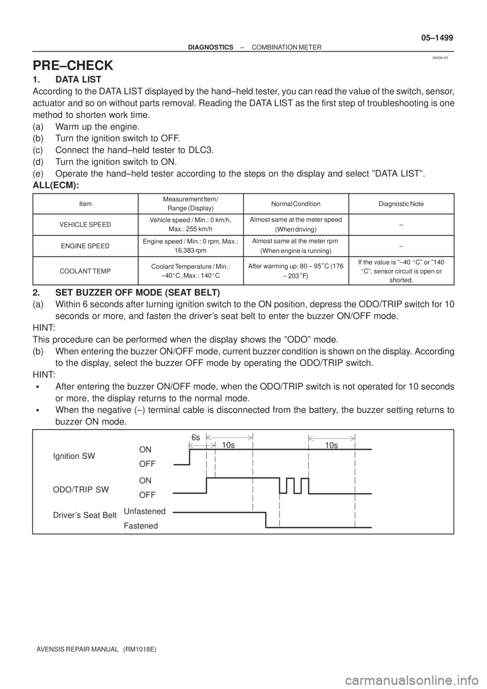
2. SET BUZZER OFF MODE (SEAT BELT)
(a) Within 6 seconds after turning ignition switch to the ON position, depress the ODO/TRIP switch for 10
seconds or more, and fasten the driver's seat belt to enter the buzzer ON/OFF mode.
HINT:
This procedure can be performed when the display shows the ºODOº mode.
(b) When entering the buzzer ON/OFF mode, current buzzer condition is shown on the display. According
to the display, select the buzzer OFF mode by operating the ODO/TRIP switch.
HINT:
�After entering the buzzer ON/OFF mode, when the ODO/TRIP switch is not operated for 10 seconds
or more, the display returns to the normal mode.
�When the negative (±) terminal cable is disconnected from the battery, the buzzer setting returns to
buzzer ON mode.
Page 1561 of 5135

± DIAGNOSTICSPOWER DOOR LOCK CONTROL SYSTEM
05±1537
AVENSIS REPAIR MANUAL (RM1018E)
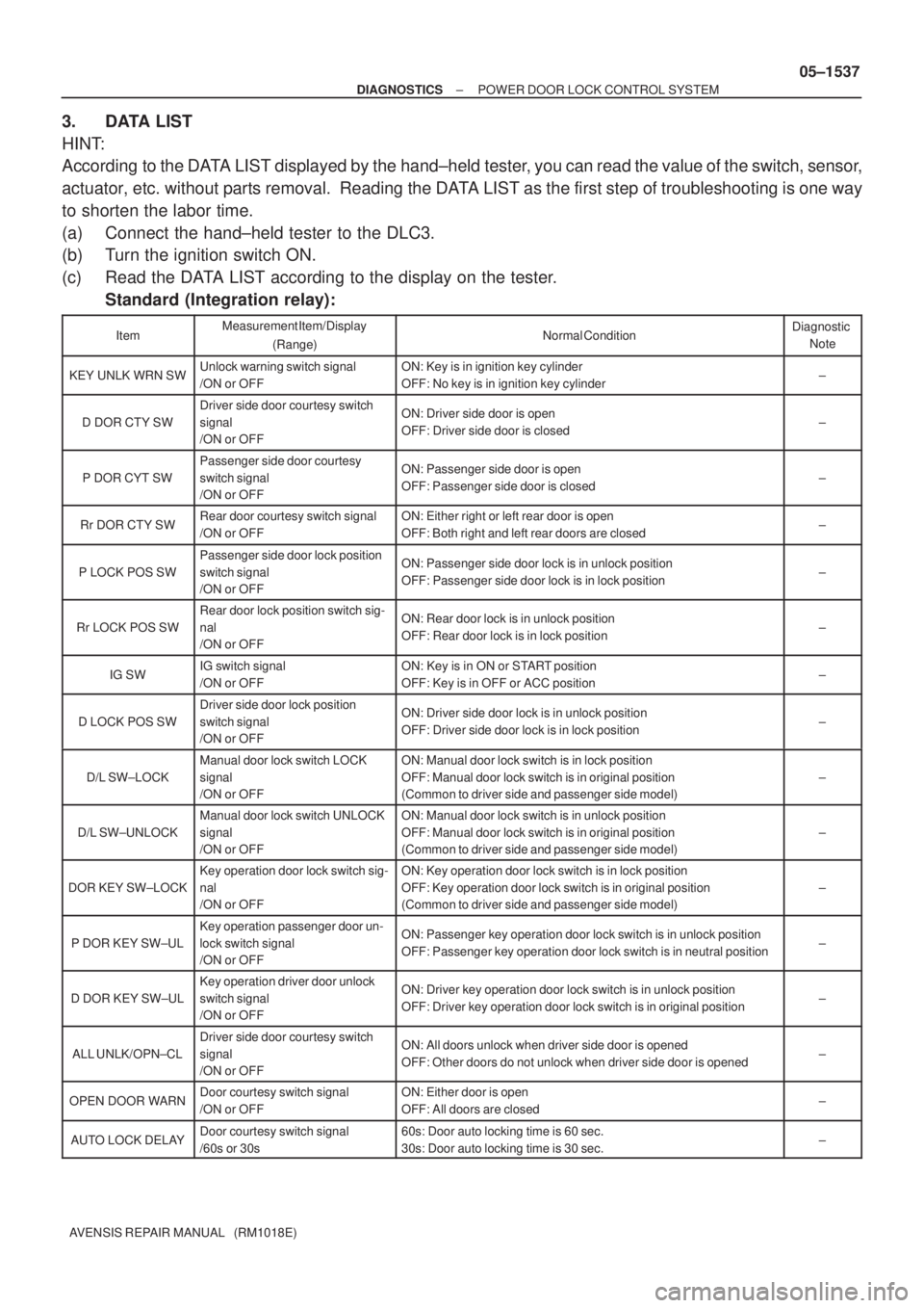
3. DATA LIST
HINT:
According to the DATA LIST displayed by the hand±held tester, you can read the value of the switch, sensor,
actuator, etc. without parts removal. Reading the DATA LIST as the first step of troubleshooting is one way
to shorten the labor time.
(a) Connect the hand±held tester to the DLC3.
(b) Turn the ignition switch ON.
(c) Read the DATA LIST according to the display on the tester.
Standard (Integration relay):
ItemMeasurement Item/Display
(Range)Normal ConditionDiagnostic
Note
KEY UNLK WRN SWUnlock warning switch signal
/ON or OFFON: Key is in ignition key cylinder
OFF: No key is in ignition key cylinder±
D DOR CTY SW
Driver side door courtesy switch
signal
/ON or OFFON: Driver side door is open
OFF: Driver side door is closed±
P DOR CYT SW
Passenger side door courtesy
switch signal
/ON or OFFON: Passenger side door is open
OFF: Passenger side door is closed±
Rr DOR CTY SWRear door courtesy switch signal
/ON or OFFON: Either right or left rear door is open
OFF: Both right and left rear doors are closed±
P LOCK POS SW
Passenger side door lock position
switch signal
/ON or OFFON: Passenger side door lock is in unlock position
OFF: Passenger side door lock is in lock position±
Rr LOCK POS SW
Rear door lock position switch sig-
nal
/ON or OFFON: Rear door lock is in unlock position
OFF: Rear door lock is in lock position±
IG SWIG switch signal
/ON or OFFON: Key is in ON or START position
OFF: Key is in OFF or ACC position±
D LOCK POS SW
Driver side door lock position
switch signal
/ON or OFFON: Driver side door lock is in unlock position
OFF: Driver side door lock is in lock position±
D/L SW±LOCK
Manual door lock switch LOCK
signal
/ON or OFFON: Manual door lock switch is in lock position
OFF: Manual door lock switch is in original position
(Common to driver side and passenger side model)
±
D/L SW±UNLOCK
Manual door lock switch UNLOCK
signal
/ON or OFFON: Manual door lock switch is in unlock position
OFF: Manual door lock switch is in original position
(Common to driver side and passenger side model)
±
DOR KEY SW±LOCK
Key operation door lock switch sig-
nal
/ON or OFFON: Key operation door lock switch is in lock position
OFF: Key operation door lock switch is in original position
(Common to driver side and passenger side model)
±
P DOR KEY SW±UL
Key operation passenger door un-
lock switch signal
/ON or OFFON: Passenger key operation door lock switch is in unlock position
OFF: Passenger key operation door lock switch is in neutral position±
D DOR KEY SW±UL
Key operation driver door unlock
switch signal
/ON or OFFON: Driver key operation door lock switch is in unlock position
OFF: Driver key operation door lock switch is in original position±
ALL UNLK/OPN±CL
Driver side door courtesy switch
signal
/ON or OFFON: All doors unlock when driver side door is opened
OFF: Other doors do not unlock when driver side door is opened±
OPEN DOOR WARNDoor courtesy switch signal
/ON or OFFON: Either door is open
OFF: All doors are closed±
AUTO LOCK DELAYDoor courtesy switch signal
/60s or 30s60s: Door auto locking time is 60 sec.
30s: Door auto locking time is 30 sec.±
Page 1562 of 5135

05±1538
± DIAGNOSTICSPOWER DOOR LOCK CONTROL SYSTEM
AVENSIS REPAIR MANUAL (RM1018E)ItemDiagnostic
Note Normal Condition Measurement Item/Display
(Range)
DOOR HANDLE SW
Back door opener switch signal
(Outside handle switch)
/ON or OFFON: Back door opener switch is pushed
OFF: Back door opener switch is not pushed±
LOCK STATUSBack door position switch signal
/UNLOCK or LOCKUNLOCK: Back door is unlock
LOCK: Back door is lock±
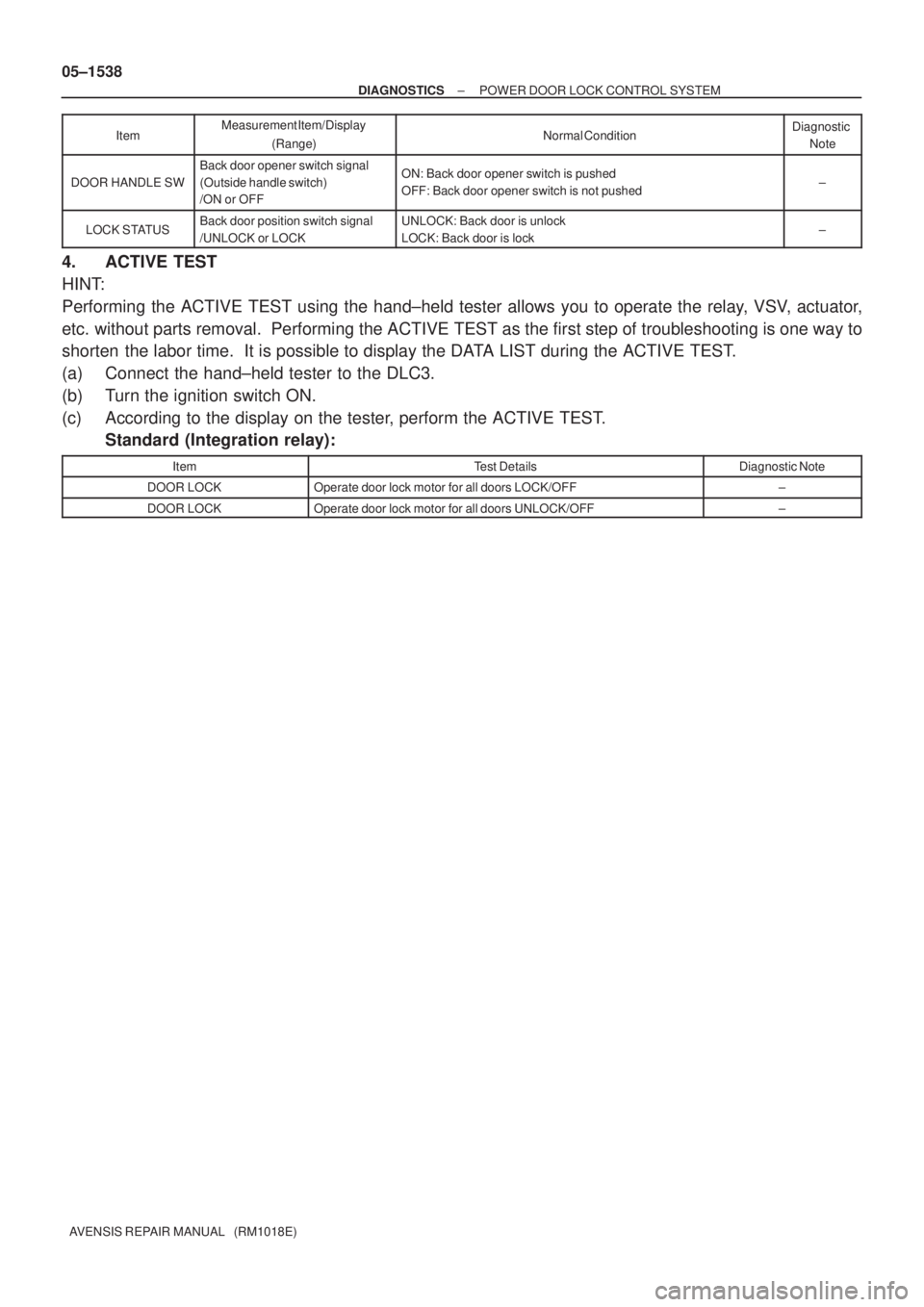
4. ACTIVE TEST
HINT:
Performing the ACTIVE TEST using the hand±held tester allows you to operate the relay, VSV, actuator,
etc. without parts removal. Performing the ACTIVE TEST as the first step of troubleshooting is one way to
shorten the labor time. It is possible to display the DATA LIST during the ACTIVE TEST.
(a) Connect the hand±held tester to the DLC3.
(b) Turn the ignition switch ON.
(c) According to the display on the tester, perform the ACTIVE TEST.
Standard (Integration relay):
ItemTest DetailsDiagnostic Note
DOOR LOCKOperate door lock motor for all doors LOCK/OFF±
DOOR LOCKOperate door lock motor for all doors UNLOCK/OFF±
Page 1641 of 5135
05±1604
± DIAGNOSTICSENGINE IMMOBILISER SYSTEM
AVENSIS REPAIR MANUAL (RM1018E)ItemNormal Condition Measurement Item/
Display (Range)
REG CODE SPACE
Memory space for key codes
registration/
NOT FUL or FULLNOT FUL: Possible to resister more key code
FULL: Impossible to register key code any more
ANTENNA COILAntenna coil condition/
NORMAL or FAILNormal: Antenna coil is normal
FAIL: Antenna coil is abnormal
5. ACTIVE TEST
HINT:
Performing the ACTIVE TEST using the hand±held tester allows you to operate the relay, VSV, actuator,
etc. without parts removal. Performing the ACTIVE TEST as the first step of troubleshooting is one way to
shorten the labor time.
(a) Connect the hand±held tester to the DLC3.
(b) Turn the ignition switch ON.
(c) Perform the ACTIVE TEST, according to the display on the tester.
Transponder key ECU:
ItemTest Details
SECURITY INDICTurn security indicator ON/OFF
Page 2003 of 5135

1302Z±03
A77123
SST
A60595E2 VC
± INTAKETURBO CHARGER SYSTEM (1CD±FTV)
13±5
AVENSIS REPAIR MANUAL (RM1018E)
ON±VEHICLE INSPECTION
1. INSPECT INTAKE AIR SYSTEM
(a) Check for leakage or clogging between the air cleaner
housing and turbocharger inlet and between the turbo-
charger outlet and cylinder head.
(1) Clogged air cleaner...Clean or replace element
(2) Hoses collapsed or deformed...Repair or replace
(3) Leakage from connections...Check each connec-
tion and repair
(4) Cracks in components...Check and replace
2. INSPECT EXHAUST SYSTEM
(a) Check for leakage or clogging between the cylinder head
and turbocharger inlet and between the turbocharger out-
let and exhaust pipe.
(1) Deformed components...Repair or replace
(2) Foreign material in passages...Remove
(3) Leakage from components...Repair or replace
(4) Cracks in components...Check and replace
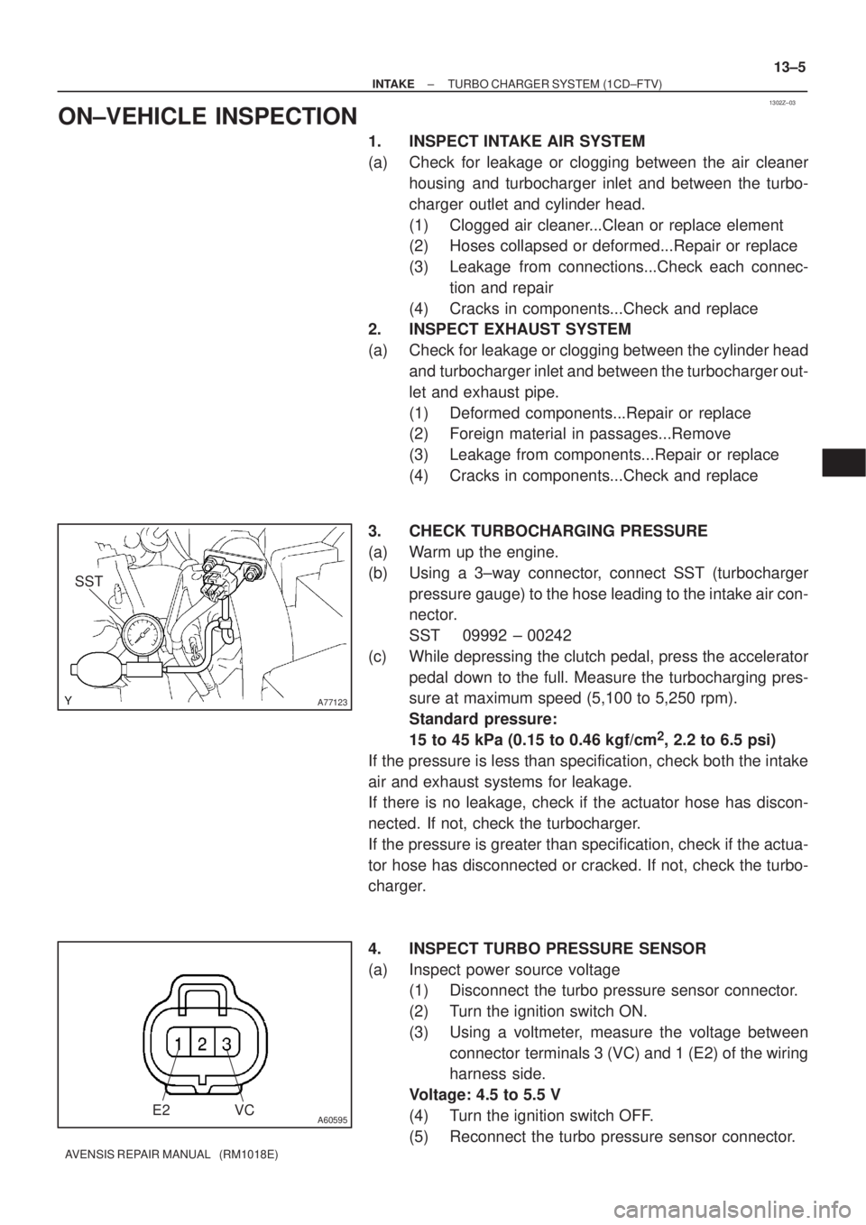
3. CHECK TURBOCHARGING PRESSURE
(a) Warm up the engine.
(b) Using a 3±way connector, connect SST (turbocharger
pressure gauge) to the hose leading to the intake air con-
nector.
SST 09992 ± 00242
(c) While depressing the clutch pedal, press the accelerator
pedal down to the full. Measure the turbocharging pres-
sure at maximum speed (5,100 to 5,250 rpm).
Standard pressure:
15 to 45 kPa (0.15 to 0.46 kgf/cm
2, 2.2 to 6.5 psi)
If the pressure is less than specification, check both the intake
air and exhaust systems for leakage.
If there is no leakage, check if the actuator hose has discon-
nected. If not, check the turbocharger.
If the pressure is greater than specification, check if the actua-
tor hose has disconnected or cracked. If not, check the turbo-
charger.
4. INSPECT TURBO PRESSURE SENSOR
(a) Inspect power source voltage
(1) Disconnect the turbo pressure sensor connector.
(2) Turn the ignition switch ON.
(3) Using a voltmeter, measure the voltage between
connector terminals 3 (VC) and 1 (E2) of the wiring
harness side.
Voltage: 4.5 to 5.5 V
(4) Turn the ignition switch OFF.
(5) Reconnect the turbo pressure sensor connector.