Page 365 of 5135
A71007
MassAir Flow Meter Crankshaft Position Sensor
Actual Valve TimingCorrection Target Valve Timing
Feedback
Duty Control ECM
Camshaft Timing
Oil Control
Valve (OCV)
Vehicle Speed Signal Engine Coolant Temp. SensorThrottle Position Sensor
Camshaft Position Sensor
± DIAGNOSTICSSFI SYSTEM (1AZ±FE)
05±169
AVENSIS REPAIR MANUAL (RM1018E)
DTC P0010/39 CAMSHAFT POSITION ºAº ACTUATOR
CIRCUIT (BANK 1)
CIRCUIT DESCRIPTION
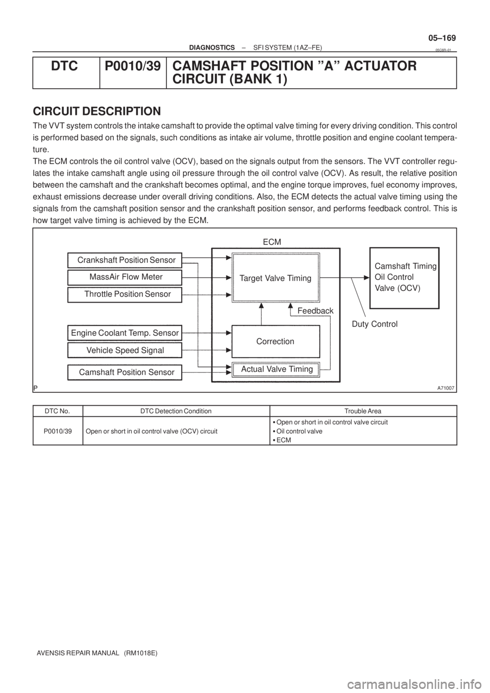
The VVT system controls the intake camshaft to provide the optimal valve timing for every driving condition. This control
is performed based on the signals, such conditions as intake air volume, throttle position and engine coolant tempera-
ture.
The ECM controls the oil control valve (OCV), based on the signals output from the sensors. The VVT controller regu-
lates the intake camshaft angle using oil pressure through the oil control valve (OCV). As result, the relative position
between the camshaft and the crankshaft becomes optimal, and the engine torque improves, fuel economy improves,
exhaust emissions decrease under overall driving conditions. Also, the ECM detects the actual valve timing using the
signals from the camshaft position sensor and the crankshaft position sensor, and performs feedback control. This is
how target valve timing is achieved by the ECM.
DTC No.DTC Detection ConditionTrouble Area
P0010/39Open or short in oil control valve (OCV) circuit
�Open or short in oil control valve circuit
�Oil control valve
�ECM
05C6R±01
Page 366 of 5135
A59779
C2
Camshaft Timing Oil
Control Valve1
2 ECM
W±G OC1+
14
Y±B OC1±
E13
15
E13
05±170
±
DIAGNOSTICS SFI SYSTEM(1AZ±FE)
AVENSIS REPAIR MANUAL (RM1018E)
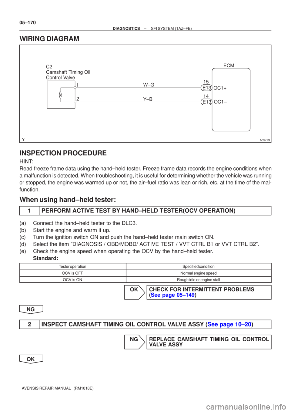
WIRING DIAGRAM
INSPECTION PROCEDURE
HINT:
Read freeze frame data using the hand±held tester. Freeze frame data records the engine conditions when
a malfunction is detected. When troubleshooting, it is useful for determi\
ning whether the vehicle was running
or stopped, the engine was warmed up or not, the air±fuel ratio was lea\
n or rich, etc. at the time of the mal-
function.
When using hand±held tester:
1PERFORM ACTIVE TEST BY HAND±HELD TESTER(OCV OPERATION)
(a)Connect the hand±held tester to the DLC3.
(b)Start the engine and warm it up.
(c)Turn the ignition switch ON and push the hand±held tester main switch \
ON.
(d)Select the item ºDIAGNOSIS / OBD/MOBD/ ACTIVE TEST / VVT CTRL B1 or V\
VT CTRL B2º.
(e)Check the engine speed when operating the OCV by the hand±held tester. Standard:
Tester operationSpecified condition
OCV is OFFNormal engine speed
OCV is ONRough idle or engine stall
OKCHECK FOR INTERMITTENT PROBLEMS (See page 05±149)
NG
2INSPECT CAMSHAFT TIMING OIL CONTROL VALVE ASSY (See page 10±20)
NG REPLACE CAMSHAFT TIMING OIL CONTROL VALVE ASSY
OK
Page 367 of 5135
A79111
OCV Signal Waveform1 msec./Division 5 V/
Division
GND
(A)(A) (A)
E13
OC1 +OC1±
A54386
Wire Harness Side
C2
Camshaft Timing Oil Control Valve
Connector
A65743ECM Connector
E13
OC1+OC1±
±
DIAGNOSTICS SFI SYSTEM(1AZ±FE)
05±171
AVENSIS REPAIR MANUAL (RM1018E)
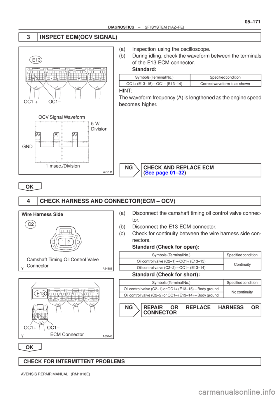
3INSPECT ECM(OCV SIGNAL)
(a)Inspection using the oscilloscope.
(b)During idling, check the waveform between the terminals
of the E13 ECM connector.
Standard:
Symbols (Terminal No.)Specified condition
OC1+ (E13±15) ± OC1± (E13±14)Correct waveform is as shown
HINT:
The waveform frequency (A) is lengthened as the engine speed
becomes higher.
NGCHECK AND REPLACE ECM (See page 01±32)
OK
4 CHECK HARNESS AND CONNECTOR(ECM ± OCV)
(a) Disconnect the camshaft timing oil control valve connec- tor.
(b) Disconnect the E13 ECM connector.
(c) Check for continuity between the wire harness side con- nectors.
Standard (Check for open):
Symbols (Terminal No.)Specified condition
Oil control valve (C2±1) ± OC1+ (E13±15)ContinuityOil control valve (C2±2) ± OC1± (E13±14)Continuity
Standard (Check for short):
Symbols (Terminal No.)Specified condition
Oil control valve (C2±1) or OC1+ (E13±15) ± Body groundNo continuityOil control valve (C2±2) or OC1± (E13±14) ± Body groundNo continuity
NG REPAIR OR REPLACE HARNESS OR CONNECTOR
OK
CHECK FOR INTERMITTENT PROBLEMS
Page 368 of 5135
A76968
C2
(±) (+)
Camshaft Timing Oil Control Valve
A79111
OCV Signal Waveform
1 msec./Division5 V/
Division
GND
(A) (A)
(A)
E13
OC1 + OC1±
05±172
± DIAGNOSTICSSFI SYSTEM (1AZ±FE)
AVENSIS REPAIR MANUAL (RM1018E)
When not using hand±held tester:
1 CHECK OPERATION OF OCV
(a) Disconnect the camshaft timing oil control valve connec-
tor.
(b) Apply battery positive voltage between the terminals of
the camshaft timing oil control valve.
(c) Check the engine speed.
Standard:
Engine speed is rough idle or engine is stalled.
NG REPLACE CAMSHAFT TIMING OIL CONTROL
VALVE ASSY
OK
2 INSPECT ECM(OCV SIGNAL)
(a) Inspection using the oscilloscope.
(b) During idling, check the waveform between the terminals
of the E13 ECM connector.
Standard:
Symbols (Terminal No.)Specified condition
OC1+ (E13±15) ± OC1± (E13±14)Correct waveform is as shown
HINT:
The waveform frequency (A) is lengthened as the engine speed
becomes higher.
NG CHECK AND REPLACE ECM
(See page )
OK
Page 369 of 5135
A54386
Wire Harness SideC2
Camshaft Timing Oil Control Valve
Connector
A65743ECM Connector
E13
OC1+OC1±
±
DIAGNOSTICS SFI SYSTEM(1AZ±FE)
05±173
AVENSIS REPAIR MANUAL (RM1018E)
3CHECK HARNESS AND CONNECTOR(ECM ± OCV)
(a)Disconnect the camshaft timing oil control valve connec-
tor.
(b)Disconnect the E13 ECM connector.
(c)Check for continuity between the wire harness side con- nectors.
Standard (Check for open):
Symbols (Terminal No.)Specified condition
Oil control valve (C2±1) ± OC1+ (E13±15)ContinuityOil control valve (C2±2) ± OC1± (E13±14)Continuity
Standard (Check for short):
Symbols (Terminal No.)Specified condition
Oil control valve (C2±1) or OC1+ (E13±15) ± Body groundNocontinuityOil control valve (C2±2) or OC1± (E13±14) ± Body groundNo continuity
NGREPAIR OR REPLACE HARNESS OR CONNECTOR
OK
CHECK FOR INTERMITTENT PROBLEMS(See page 05±149)
Page 370 of 5135
A76888
FL MAIN
StarterCircuit
Opening Relay
Start Position SWEFI Relay
AM2
BatteryECM
STA MREL Ignition SWFuel Pump
ST2
ST
Relay
(NE Signal) (A/T)FC
EFISTTr
(M/T)
(A/T) AM2 05±264
± DIAGNOSTICSSFI SYSTEM (1AZ±FE)
AVENSIS REPAIR MANUAL (RM1018E)
FUEL PUMP CONTROL CIRCUIT
CIRCUIT DESCRIPTION
In the diagram below, when the engine is cranked, current flows from terminal ST2 of the ignition switch to
the starter relay coil and also current flows to terminal STA of the ECM (STA signal).
When the STA signal and NE signal are input to the ECM, Tr is turned ON, current flows to the coil of the
E.F.I. circuit opening relay, the relay switches on, power is supplied to the fuel pump and the fuel pump oper-
ates.
While the NE signal is generated (engine running), the ECM keeps Tr ON (circuit opening relay ON) and the
fuel pump also keeps operating.
05C79±01
Page 380 of 5135
A79123
I13
Ignition SW
4
6
IE4B±R
IP1 1
1(LHD)
B±R
11B±Y B±R
DHIGN
DA18 2Driver Side J/B
22
EFI
1 AM2
1
1A 1
B±GEngine Room
R/B No.1
Engine Room
J/B No.1 (RHD)
14A
14BEngine Room
J/B No.4
B±G
FL MAIN
BatteryB±W
(LHD)B±W
(LHD)
J8
J/C CC B±W
(RHD)B±W
(RHD)
J/C J26 J27AE
ECM
IGSW
E99
GR
IE12
GR
E98
MREL
44
51
EFI
Relay+B 1
E9 B±R
Engine Room
R/B No.4
Engine Room
R/B No.444
4
4E1 7
E12
IK1 8
1
2
EF ECW±B
B±RBR B±W
EFI
No.132
B±R
EA1 12
± DIAGNOSTICSSFI SYSTEM (1AZ±FE)
05±257
AVENSIS REPAIR MANUAL (RM1018E)
ECM POWER SOURCE CIRCUIT
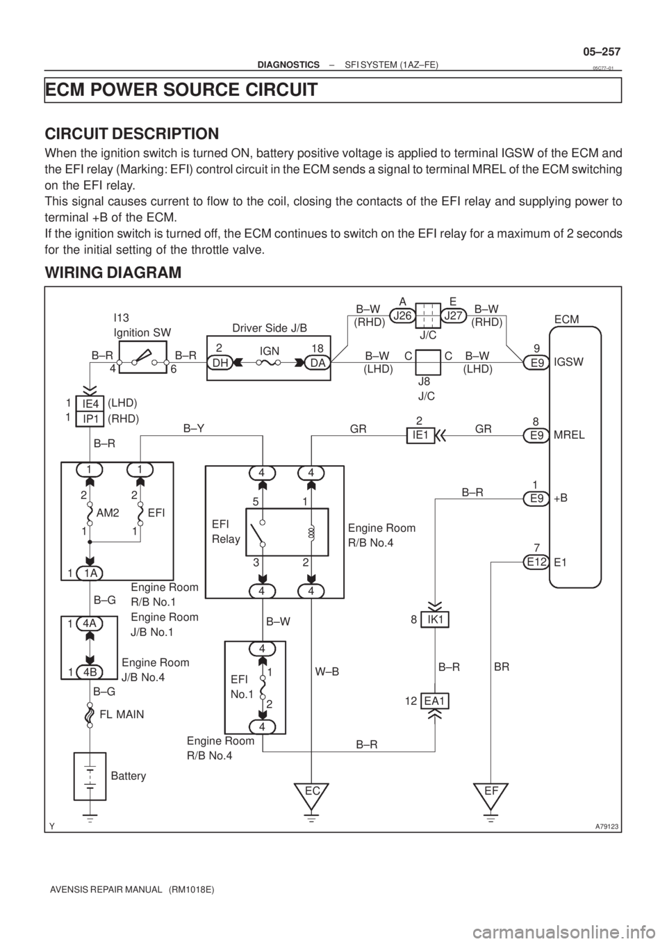
CIRCUIT DESCRIPTION
When the ignition switch is turned ON, battery positive voltage is applied to terminal IGSW of the ECM and
the EFI relay (Marking: EFI) control circuit in the ECM sends a signal to terminal MREL of the ECM switching
on the EFI relay.
This signal causes current to flow to the coil, closing the contacts of the EFI relay and supplying power to
terminal +B of the ECM.
If the ignition switch is turned off, the ECM continues to switch on the EFI relay for a maximum of 2 seconds
for the initial setting of the throttle valve.
WIRING DIAGRAM
05C77±01
Page 402 of 5135
05±232
± DIAGNOSTICSSFI SYSTEM (1AZ±FE)
AVENSIS REPAIR MANUAL (RM1018E)
DTC P0351/14 IGNITION COIL ºAº PRIMARY/SECONDARY
CIRCUIT
DTC P0352/15 IGNITION COIL ºBº PRIMARY/SECONDARY
CIRCUIT
DTC P0353/14 IGNITION COIL ºCº PRIMARY/SECONDARY
CIRCUIT
DTC P0354/15 IGNITION COIL ºDº PRIMARY/SECONDARY
CIRCUIT
CIRCUIT DESCRIPTION
HINT:
�These DTCs indicate a malfunction related to primary circuit.
�If DTC P0351/14 is displayed, check No.1 ignition coil with igniter circuit.
�If DTC P0352/15 is displayed, check No.2 ignition coil with igniter circuit.
�If DTC P0353/14 is displayed, check No.3 ignition coil with igniter circuit.
�If DTC P0354/15 is displayed, check No.4 ignition coil with igniter circuit.
A Direct Ignition System (DIS) has been adopted. The DIS improves the ignition timing accuracy, reduces
high±voltage loss, and enhances the overall reliability of the ignition system by eliminating the distributor.
The DIS is a 1±cylinder ignition system which ignites one cylinder with one ignition coil. In the 1±cylinder
ignition system, the one spark plug is connected to the end of the secondary winding. High voltage generated
in the secondary winding is applied directly to the spark plug. The spark of the spark plug passes from the
center electrode to the ground electrode.
The ECM determines the ignition timing and outputs the ignition (IGT) signals for each cylinder. Based on
the IGT signals, the power transistors in the igniter cut off the current to the primary coil in the ignition coil
is supplied to the spark plug that is connected to the end of the secondary coil. At the same time, the igniter
also sends an ignition confirmation (IGF) signal as a fail±safe measure to the ECM.
05C72±01