Page 263 of 5135
������A79093
ECM
EH W±B E13
IGT1
IGF
E13
E13
E13
E13 23 IGT2
IGT3
IGT4
8
10
11
R±W
3
2
1
I1
Ignition Coil and
Igniter No.1
I2
Ignition Coil and
Igniter No.2
I3
Ignition Coil and
Igniter No.3
I4
Ignition Coil and
Igniter No.4
R±B
W±B 4 3
2
B±R
1
1
1
B±R
R±B
33
2
2
L±YW±R
W±R W±R
4 4 4
W±B
W±B
W±B
W±B
R±B
W±R
R±B R±B
From Terminal 3
of IG2 Relay
(See Page 05±124)
W±B LG±B
P
W±R
W±R
W±R 9
R±B 1N2
Noise
Filter R±B
8 EA1
±
DIAGNOSTICS SFI SYSTEM (1ZZ±FE/3ZZ±FE)
05±105
AVENSIS REPAIR MANUAL (RM1018E)
WIRING DIAGRAM
Page 264 of 5135

A18294
IGT4IGT3IGT2IGT1
ECM Connector
E1
E13E12
IGF
A63956
CH1
(IGT1 ± 4)
CH2
(IGF1)
GND
GND
05±106
±
DIAGNOSTICS SFI SYSTEM(1ZZ±FE/3ZZ±FE)
AVENSIS REPAIR MANUAL (RM1018E)
INSPECTION PROCEDURE
HINT:
Read freeze frame data using \f���� ����\b�\f��\f�
� Freeze frame data records the engine conditions when
a malfunction is detected. When troubleshooting, it is useful for determi\
ning whether the vehicle was running
or stopped, the engine was warmed up or not, the air±fuel ratio was lea\
n or rich, etc. at the time of the mal-
function.
1PERFORM SIMULATION TEST
(a)Clear the DTC (See page 05±5)
(b)Shuffle arrangement of the ighition coil and igniters.
NOTICE:
Do not shuffle the connectors.
(c)Perform the simulation test.
(d)Clear the DTC (See page 05±5) Result:
Display (DTC output)Proceed to
The same DTC is output againA
The other DTC is outputB
BREPLACE IGNITION COIL
A
2INSPECT ECM(IGT1, IGT2, IGT3, IGT4 AND IGF SIGNAL)
(a)Inspection using the oscilloscope.
(b)During cranking or idling, check the waveform between terminals IGT1 to IGT4 and E1, and IGF1 and E1 of the
ECM connector.
Standard:
ItemContents
TerminalCH1: IGT1, IGT2, IGT3, IGT4 ± E1
CH2: IGF ± E1
Equipment Set2V/DIV, 20ms/DIV
ConditionWhile the engine is cranking or idling
HINT:
Correct waveform is as shown in the diagram on the left.
NGCHECK AND REPLACE ECM (See page 01±32)
OK
Page 265 of 5135
A54393
+B (+) GND (±)
Ignition Coil and Igniter Connector Wire Harness Side
I1
I2I3I4
A65743
E13
ECM Connector
IGT4IGT3
IGT2IGT1
IGF
A54393
IGT Wire Harness Side
Ignition Coil and Igniter ConnectorIGF I1
I2I3I4
± DIAGNOSTICSSFI SYSTEM (1ZZ±FE/3ZZ±FE)
05±107
AVENSIS REPAIR MANUAL (RM1018E)
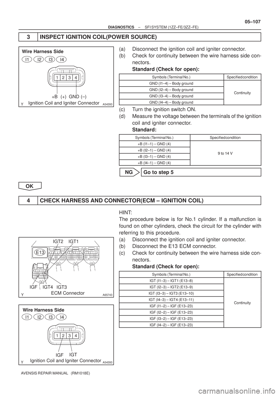
3 INSPECT IGNITION COIL(POWER SOURCE)
(a) Disconnect the ignition coil and igniter connector.
(b) Check for continuity between the wire harness side con-
nectors.
Standard (Check for open):
Symbols (Terminal No.)Specified condition
GND (I1±4) ± Body ground
GND (I2±4) ± Body groundContinuityGND (I3±4) ± Body groundContinuity
GND (I4±4) ± Body ground
(c) Turn the ignition switch ON.
(d) Measure the voltage between the terminals of the ignition
coil and igniter connector.
Standard:
Symbols (Terminal No.)Specified condition
+B (I1±1) ± GND (4)
+B (I2±1) ± GND (4)9to14V+B (I3±1) ± GND (4)9 to 14 V
+B (I4±1) ± GND (4)
NG Go to step 5
OK
4 CHECK HARNESS AND CONNECTOR(ECM ± IGNITION COIL)
HINT:
The procedure below is for No.1 cylinder. If a malfunction is
found on other cylinders, check the circuit for the cylinder with
referring to this procedure.
(a) Disconnect the ignition coil and igniter connector.
(b) Disconnect the E13 ECM connector.
(c) Check for continuity between the wire harness side con-
nectors.
Standard (Check for open):
Symbols (Terminal No.)Specified condition
IGT (I1±3) ± IGT1 (E13±8)
IGT (I2±3) ± IGT2 (E13±9)
IGT (I3±3) ± IGT3 (E13±10)
IGT (I4±3) ± IGT4 (E13±11)ContinuityIGF (I1±2) ± IGF (E13±23)Continuity
IGF (I2±2) ± IGF (E13±23)
IGF (I3±2) ± IGF (E13±23)
IGF (I4±2) ± IGF (E13±23)
Page 266 of 5135
B16200
05±108
± DIAGNOSTICSSFI SYSTEM (1ZZ±FE/3ZZ±FE)
AVENSIS REPAIR MANUAL (RM1018E)
Standard (Check for short):
Symbols (Terminal No.)Specified condition
IGT (I1±3) or IGT1 (E13±8) ± Body ground
IGT (I2±3) or IGT2 (E13±9) ± Body ground
IGT (I3±3) or IGT3 (E13±10) ± Body ground
IGT (I4±3) or IGT4 (E13±11) ± Body groundNo continuityIGF (I1±2) or IGF (E13±23) ± Body groundNo continuity
IGF (I2±2) or IGF (E13±23) ± Body ground
IGF (I3±2) or IGF (E13±23) ± Body ground
IGF (I4±2) or IGF (E13±23) ± Body ground
NG REPLACE HARNESS OR CONNECTOR
OK
REPLACE IGNITION COIL
5 INSPECT IG2 RELAY
(a) Remove the IG2 relay from the engine room R/B No.4.
(b) Inspect the IG2 relay.
Standard:
Terminal No.Specified condition
1 ± 2Continuity
No Continuity
3 ± 5Continuity
(Apply battery voltage Terminals 1 and 2)
NG REPLACE IG2 RELAY
OK
Page 267 of 5135
A54393
+B
Ignition Coil and Igniter Connector
Wire Harness Side
I1
I2I3I4
������A79064IG2 Relay
Engine Room R/B No.4
±
DIAGNOSTICS SFI SYSTEM(1ZZ±FE/3ZZ±FE)
05±109
AVENSIS REPAIR MANUAL (RM1018E)
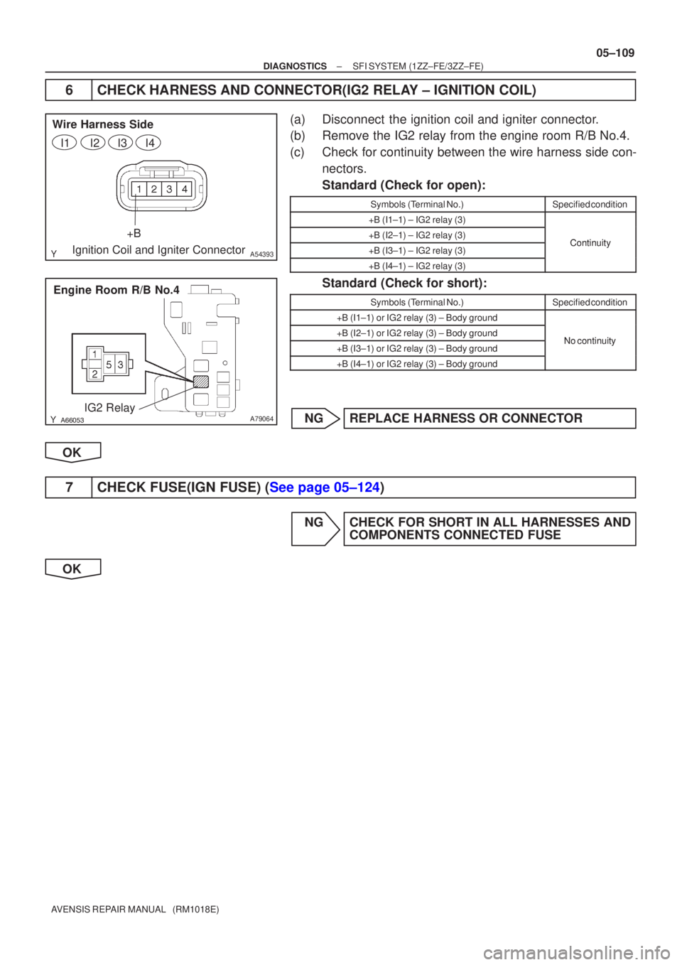
6CHECK HARNESS AND CONNECTOR(IG2 RELAY ± IGNITION COIL)
(a)Disconnect the ignition coil and igniter connector.
(b)Remove the IG2 relay from the engine room R/B No.4.
(c)Check for continuity between the wire harness side con-
nectors.
Standard (Check for open):
Symbols (Terminal No.)Specified condition
+B (I1±1) ± IG2 relay (3)
+B (I2±1) ± IG2 relay (3)Continuity+B (I3±1) ± IG2 relay (3)Continuity
+B (I4±1) ± IG2 relay (3)
Standard (Check for short):
Symbols (Terminal No.)Specified condition
+B (I1±1) or IG2 relay (3) ± Body ground
+B (I2±1) or IG2 relay (3) ± Body groundNocontinuity+B (I3±1) or IG2 relay (3) ± Body groundNo continuity
+B (I4±1) or IG2 relay (3) ± Body ground
NGREPLACE HARNESS OR CONNECTOR
OK
7CHECK FUSE(IGN FUSE) (See page 05±124)
NG CHECK FOR SHORT IN ALL HARNESSES AND COMPONENTS CONNECTED FUSE
OK
Page 281 of 5135
A63955
GND
CH1
(G2)
CH2
(NE+) GND
05±88
±
DIAGNOSTICS SFI SYSTEM(1ZZ±FE/3ZZ±FE)
AVENSIS REPAIR MANUAL (RM1018E)
DTCP0340CAMSHAFT POSITION SENSOR CIRCUIT MALFUNCTION
CIRCUIT DESCRIPTION
The camshaft position sensor (G2 signal) consists of a magnet, iron core \
and pickup coil.
The G2 signal plate has 3 teeth on its outer circumference and is instal\
led on the camshaft timing pulley.
When the camshafts rotate, the protrusion on the signal plate and the air gap on the pickup coil changes,
causing fluctuations in the magnetic field and generating an electromoti\
ve force in the pickup coil.
The NE signal plate (crankshaft timing pulley) has 34 teeth and is instal\
led to the crankshaft. The NE signal
sensor generates 34 signals at every engine revolution. The ECM detects \
the crankshaft angle and the en-
gine revolution based on the NE signals, and the cylinder and the angle of the VVT based on the combination
of the G2 and NE signals.
DTC No.DTC Detecting ConditionTrouble Area
P0340
�No camshaft position sensor signal to the ECM during crank-
ing
� Open in NE± circuit
�Open or short in camshaft position sensor circuit
� Camshaft position sensor
� Intake camshaft
� Timing chain has jumped a tooth
� ECM
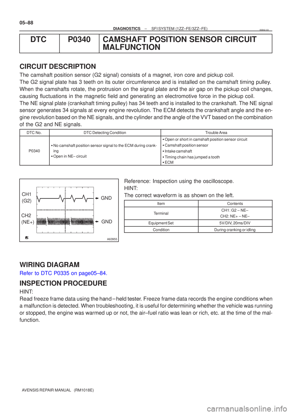
Reference: Inspection using the oscilloscope.
HINT:
The correct waveform is as shown on the left.
ItemContents
TerminalCH1: G2 ± NE±
CH2: NE+ ± NE±
Equipment Set5V/DIV, 20ms/DIV
ConditionDuring cranking or idling
WIRING DIAGRAM
Refer to DTC P0335 on page05±84.
INSPECTION PROCEDURE
HINT:
Read freeze frame data using \f�� �� ����\b� \f��\f�
� Freeze frame data records the engine conditions when
a malfunction is detected. When troubleshooting, it is useful for determi\
ning whether the vehicle was running
or stopped, the engine was warmed up or not, the air±fuel ratio was lea\
n or rich, etc. at the time of the mal-
function.
05B42±03
Page 282 of 5135
A73303
G±G+
Camshaft Position Sensor C1
��
A66132
G+G±
Camshaft Position Sensor Connector Wire Harness Side
C1
A65743NE± G2
E13
ECM Connector
± DIAGNOSTICSSFI SYSTEM (1ZZ±FE/3ZZ±FE)
05±89
AVENSIS REPAIR MANUAL (RM1018E)
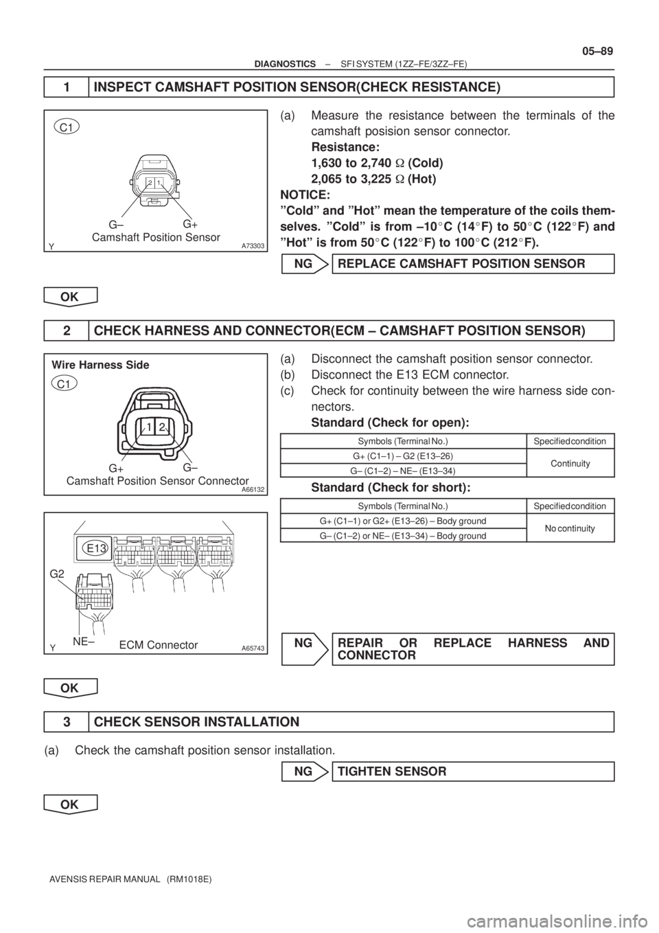
1 INSPECT CAMSHAFT POSITION SENSOR(CHECK RESISTANCE)
(a) Measure the resistance between the terminals of the
camshaft posision sensor connector.
Resistance:
1,630 to 2,740 � (Cold)
2,065 to 3,225 �(Hot)
NOTICE:
ºColdº and ºHotº mean the temperature of the coils them-
selves. ºColdº is from ±10�C (14�F) to 50�C (122�F) and
ºHotº is from 50�C (122�F) to 100�C (212�F).
NG REPLACE CAMSHAFT POSITION SENSOR
OK
2 CHECK HARNESS AND CONNECTOR(ECM ± CAMSHAFT POSITION SENSOR)
(a) Disconnect the camshaft position sensor connector.
(b) Disconnect the E13 ECM connector.
(c) Check for continuity between the wire harness side con-
nectors.
Standard (Check for open):
Symbols (Terminal No.)Specified condition
G+ (C1±1) ± G2 (E13±26)ContinuityG± (C1±2) ± NE± (E13±34)Continuity
Standard (Check for short):
Symbols (Terminal No.)Specified condition
G+ (C1±1) or G2+ (E13±26) ± Body groundNo continuityG± (C1±2) or NE± (E13±34) ± Body groundNo continuity
NG REPAIR OR REPLACE HARNESS AND
CONNECTOR
OK
3 CHECK SENSOR INSTALLATION
(a) Check the camshaft position sensor installation.
NG TIGHTEN SENSOR
OK
Page 284 of 5135
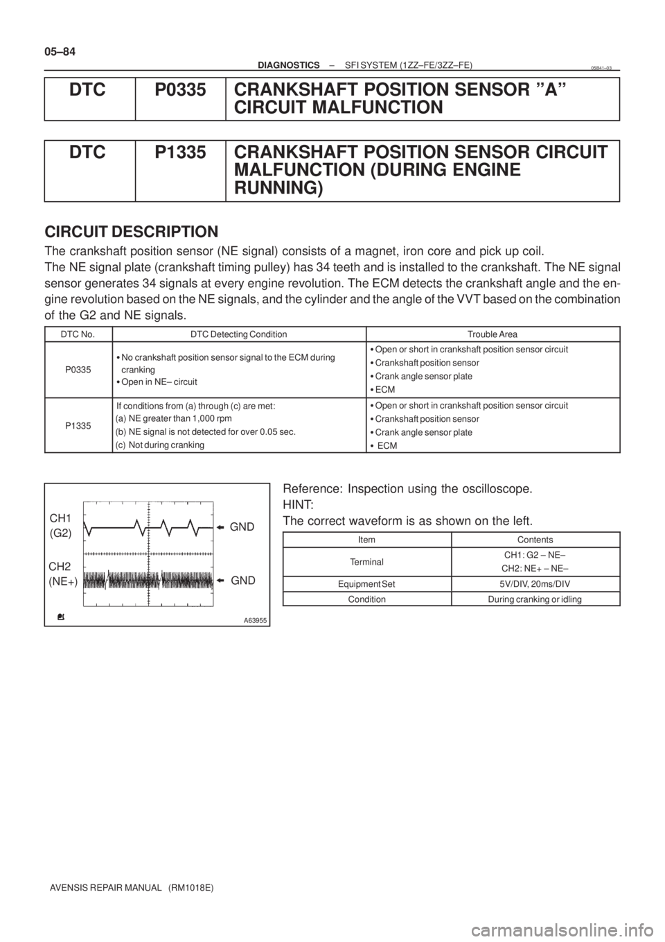
A63955
GND CH1
(G2)
CH2
(NE+)GND 05±84
± DIAGNOSTICSSFI SYSTEM (1ZZ±FE/3ZZ±FE)
AVENSIS REPAIR MANUAL (RM1018E)
DTC P0335 CRANKSHAFT POSITION SENSOR ºAº
CIRCUIT MALFUNCTION
DTC P1335 CRANKSHAFT POSITION SENSOR CIRCUIT
MALFUNCTION (DURING ENGINE
RUNNING)
CIRCUIT DESCRIPTION
The crankshaft position sensor (NE signal) consists of a magnet, iron core and pick up coil.
The NE signal plate (crankshaft timing pulley) has 34 teeth and is installed to the crankshaft. The NE signal
sensor generates 34 signals at every engine revolution. The ECM detects the crankshaft angle and the en-
gine revolution based on the NE signals, and the cylinder and the angle of the VVT based on the combination
of the G2 and NE signals.
DTC No.DTC Detecting ConditionTrouble Area
P0335
�No crankshaft position sensor signal to the ECM during
cranking
�Open in NE± circuit�Open or short in crankshaft position sensor circuit
�Crankshaft position sensor
�Crank angle sensor plate
�ECM
P1335
If conditions from (a) through (c) are met:
(a) NE greater than 1,000 rpm
(b) NE signal is not detected for over 0.05 sec.
(c) Not during cranking�Open or short in crankshaft position sensor circuit
�Crankshaft position sensor
�Crank angle sensor plate
� ECM
Reference: Inspection using the oscilloscope.
HINT:
The correct waveform is as shown on the left.
ItemContents
TerminalCH1: G2 ± NE±
CH2: NE+ ± NE±
Equipment Set5V/DIV, 20ms/DIV
ConditionDuring cranking or idling
05B41±03