Page 502 of 5135
A59779
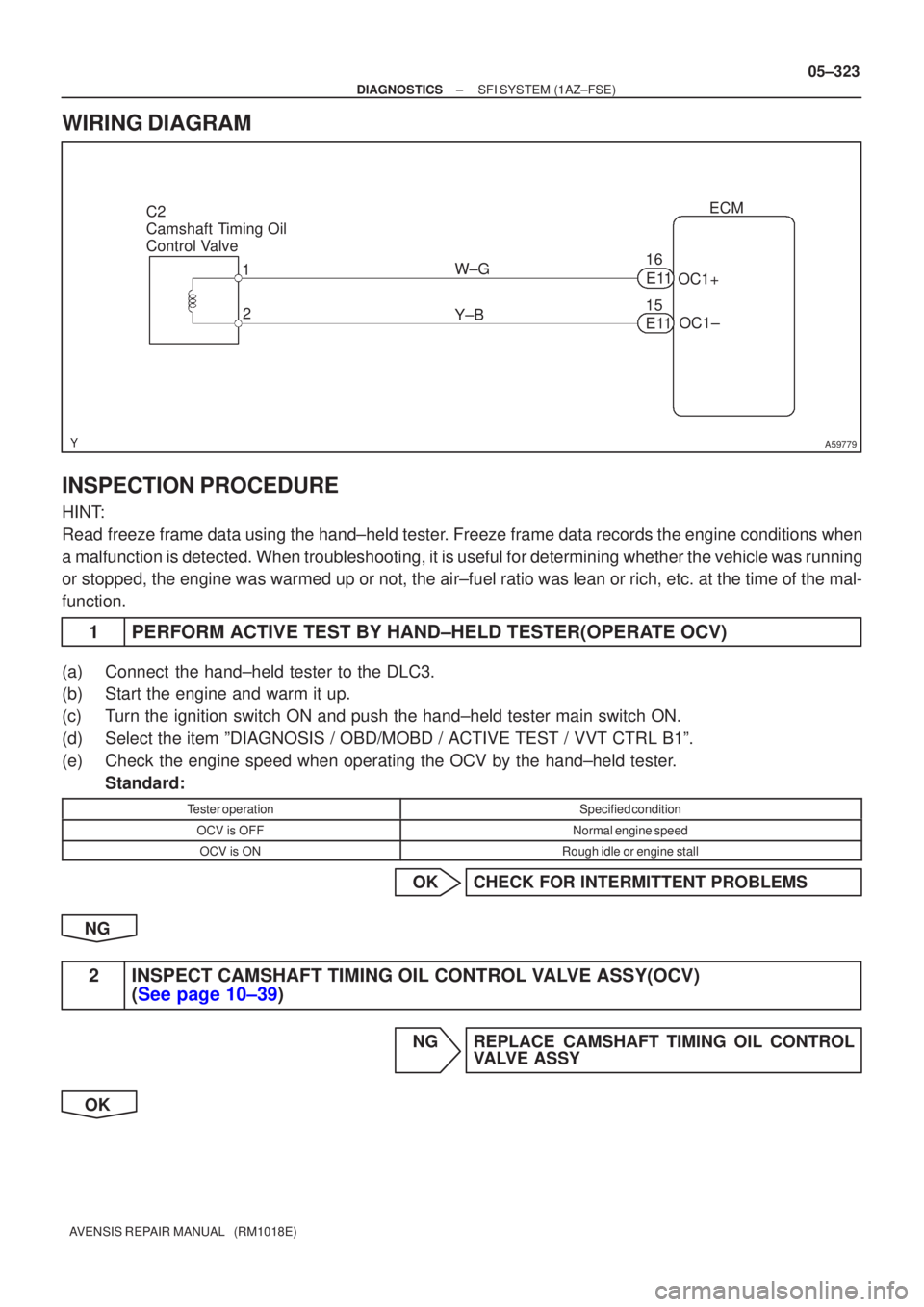
C2
Camshaft Timing Oil
Control Valve1
2 ECM
W±G OC1+
15
Y±B OC1±
E11
16
E11
±
DIAGNOSTICS SFI SYSTEM(1AZ±FSE)
05±323
AVENSIS REPAIR MANUAL (RM1018E)
WIRING DIAGRAM
INSPECTION PROCEDURE
HINT:
Read freeze frame data using the hand±held tester. Freeze frame data records the engine conditions when
a malfunction is detected. When troubleshooting, it is useful for determi\
ning whether the vehicle was running
or stopped, the engine was warmed up or not, the air±fuel ratio was lea\
n or rich, etc. at the time of the mal-
function.
1PERFORM ACTIVE TEST BY HAND±HELD TESTER(OPERATE OCV)
(a)Connect the hand±held tester to the DLC3.
(b)Start the engine and warm it up.
(c)Turn the ignition switch ON and push the hand±held tester main switch \
ON.
(d)Select the item ºDIAGNOSIS / OBD/MOBD / ACTIVE TEST / VVT CTRL B1º\
.
(e)Check the engine speed when operating the OCV by the hand±held tester.
Standard:
Tester operationSpecified condition
OCV is OFFNormal engine speed
OCV is ONRough idle or engine stall
OKCHECK FOR INTERMITTENT PROBLEMS
NG
2INSPECT CAMSHAFT TIMING OIL CONTROL VALVE ASSY(OCV) (See page 10±39)
NG REPLACE CAMSHAFT TIMING OIL CONTROL VALVE ASSY
OK
Page 504 of 5135
05CDX±01
05±320
±
DIAGNOSTICS SFI SYSTEM(1AZ±FSE)
AVENSIS REPAIR MANUAL (RM1018E)
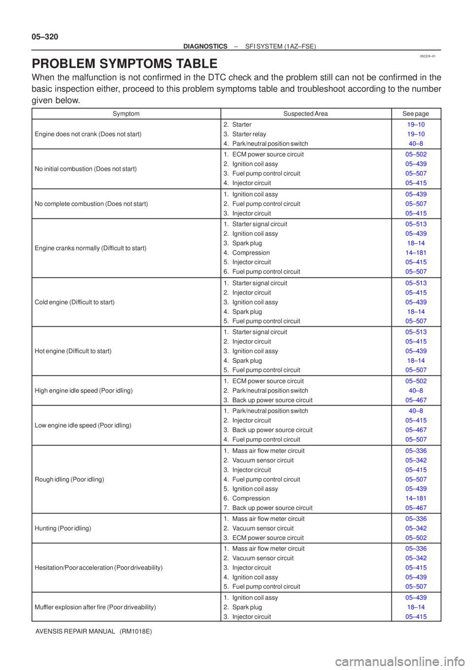
PROBLEM SYMPTOMS TABLE
When the malfunction is not confirmed in the DTC check and the problem still\
can not be confirmed in the
basic inspection either, proceed to this problem symptoms table and troubleshoot according to the number
given below.
SymptomSuspected AreaSee page
Engine does not crank (Does not start)
2. Starter
3. Starter relay
4. Park/neutral position switch19±10
19±10 40±8
No initial combustion (Does not start)
1. ECM power source circuit
2. Ignition coil assy
3. Fuel pump control circuit
4. Injector circuit05±502
05±439
05±507
05±415
No complete combustion (Does not start)
1. Ignition coil assy
2. Fuel pump control circuit
3. Injector circuit05±439
05±507
05±415
Engine cranks normally (Difficult to start)
1. Starter signal circuit
2. Ignition coil assy
3. Spark plug
4. Compression
5. Injector circuit
6. Fuel pump control circuit05±513
05±43918±14
14±181
05±415
05±507
Cold engine (Difficult to start)
1. Starter signal circuit
2. Injector circuit
3. Ignition coil assy
4. Spark plug
5. Fuel pump control circuit05±513
05±415
05±439 18±14
05±507
Hot engine (Difficult to start)
1. Starter signal circuit
2. Injector circuit
3. Ignition coil assy
4. Spark plug
5. Fuel pump control circuit05±513
05±415
05±439
18±14
05±507
High engine idle speed (Poor idling)
1. ECM power source circuit
2. Park/neutral position switch
3. Back up power source circuit05±502
40±8
05±467
Low engine idle speed (Poor idling)
1. Park/neutral position switch
2. Injector circuit
3. Back up power source circuit
4. Fuel pump control circuit40±8
05±415
05±467
05±507
Rough idling (Poor idling)
1. Mass air flow meter circuit
2. Vacuum sensor circuit
3. Injector circuit
4. Fuel pump control circuit
5. Ignition coil assy
6. Compression
7. Back up power source circuit05±336
05±342
05±415
05±507
05±439
14±181
05±467
Hunting (Poor idling)
1. Mass air flow meter circuit
2. Vacuum sensor circuit
3. ECM power source circuit05±336
05±342
05±502
Hesitation/Poor acceleration (Poor driveability)
1. Mass air flow meter circuit
2. Vacuum sensor circuit
3. Injector circuit
4. Ignition coil assy
5. Fuel pump control circuit05±336
05±342
05±415
05±439
05±507
Muffler explosion after fire (Poor driveability)
1. Ignition coil assy
2. Spark plug
3. Injector circuit05±439 18±14
05±415
Page 508 of 5135
A76903
NE+ G2+
NE±ECM ConnectorE11
A59781
± DIAGNOSTICSSFI SYSTEM (1AZ±FSE)
05±433
AVENSIS REPAIR MANUAL (RM1018E)
DTC P0335 CRANKSHAFT POSITION SENSOR ºAº
CIRCUIT
DTC P0339 CRANKSHAFT POSITION SENSOR ºAº
CIRCUIT INTERMITTENT
CIRCUIT DESCRIPTION
The crankshaft position sensor (NE signal) consists of a magnet, iron core and pick up coil.
The NE signal plate (crankshaft position sensor plate No. 1) has 34 teeth and is installed on the crankshaft.
The NE signal sensor generates 34 signals at every engine revolution. The ECM detects the crankshaft
angle and the engine revolution based on the NE signal, and the cylinder and the angle of the VVT based
on the combination of the G2 and NE signal.
DTC No.DTC Detection ConditionTrouble Area
P0335
No crankshaft position sensor (NE) signal to ECM during
cranking for 3 sec. or more (2 trip detection logic).
P0335No crankshaft position sensor (NE) signal to ECM with engine
speed 600 rpm or more (2 trip detection logic).
Open or short in crankshaft position sensor circuit
P0339
In condition (a), (b) and (c), when no crankshaft position sen-
sor (NE) signal is input for 0.05 sec. or more
(1 trip detection logic):
(a) Engine revolution 1,000 rpm or more
(b) STA signal is OFF
(c) 3 sec. or more has been lapsed after STA signal is switched
from ON to OFF.�Open or short in crankshaft position sensor circuit
�Crankshaft position sensor
�Signal plate (crankshaft position sensor plate No. 1)
�ECM
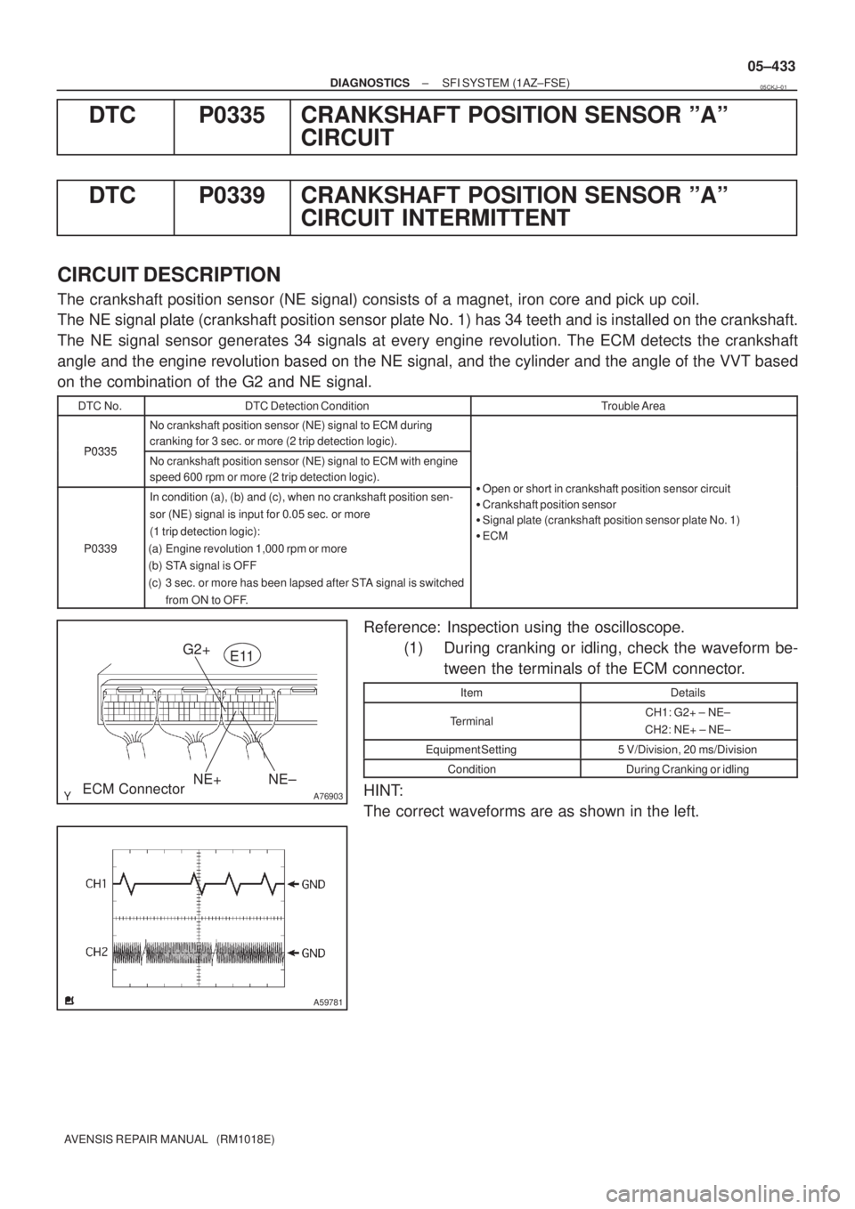
Reference: Inspection using the oscilloscope.
(1) During cranking or idling, check the waveform be-
tween the terminals of the ECM connector.
ItemDetails
TerminalCH1: G2+ ± NE±
CH2: NE+ ± NE±
Equipment Setting5 V/Division, 20 ms/Division
ConditionDuring Cranking or idling
HINT:
The correct waveforms are as shown in the left.
05CKJ±01
Page 509 of 5135
A76874
C1
Camshaft Position Sensor
C6
Crankshaft Position SensorR W
2 1
EE BR
G J12
J/CE1127ECM
G2+
NE+
NE± (Shielded)
R
BRE11
E1125
24
2 1
(Shielded)E E
E
R R
Crankshaft
Position
Sensor
Plate No. 1Camshaft
Timing
Pulley LH
A64984Crankshaft Position Sensor Component Side
C6
05±434
± DIAGNOSTICSSFI SYSTEM (1AZ±FSE)
AVENSIS REPAIR MANUAL (RM1018E)
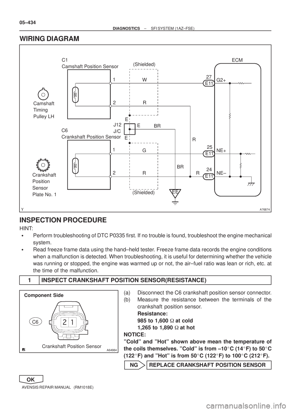
WIRING DIAGRAM
INSPECTION PROCEDURE
HINT:
�Perform troubleshooting of DTC P0335 first. If no trouble is found, troubleshoot the engine mechanical
system.
�Read freeze frame data using the hand±held tester. Freeze frame data records the engine conditions
when a malfunction is detected. When troubleshooting, it is useful for determining whether the vehicle
was running or stopped, the engine was warmed up or not, the air±fuel ratio was lean or rich, etc. at
the time of the malfunction.
1 INSPECT CRANKSHAFT POSITION SENSOR(RESISTANCE)
(a) Disconnect the C6 crankshaft position sensor connector.
(b) Measure the resistance between the terminals of the
crankshaft position sensor.
Resistance:
985 to 1,600 �at cold
1,265 to 1,890 �at hot
NOTICE:
ºColdº and ºHotº shown above mean the temperature of
the coils themselves. ºColdº is from ±10�C (14�F) to 50�C
(122�F) and ºHotº is from 50�C (122�F) to 100�C (212�F).
NG REPLACE CRANKSHAFT POSITION SENSOR
OK
Page 581 of 5135

± DIAGNOSTICSSFI SYSTEM (1AZ±FSE)
05±439
AVENSIS REPAIR MANUAL (RM1018E)
DTC P0351 IGNITION COIL ºAº PRIMARY/SECONDARY
CIRCUIT
DTC P0352 IGNITION COIL ºBº PRIMARY/SECONDARY
CIRCUIT
DTC P0353 IGNITION COIL ºCº PRIMARY/SECONDARY
CIRCUIT
DTC P0354 IGNITION COIL ºDº PRIMARY/SECONDARY
CIRCUIT
HINT:
�These DTCs indicate a malfunction related to primary circuit.
�If DTC P0351 is displayed, check No. 1 ignition coil with igniter circuit.
�If DTC P0352 is displayed, check No. 2 ignition coil with igniter circuit.
�If DTC P0353 is displayed, check No. 3 ignition coil with igniter circuit.
�If DTC P0354 is displayed, check No. 4 ignition coil with igniter circuit.
CIRCUIT DESCRIPTION
A Direct Ignition System (DIS) has been adopted. The DIS improves the ignition timing accuracy, reduces
high±voltage loss, and enhances the overall reliability of the ignition system by eliminating the distributor.
The DIS is a 1±cylinder ignition system which ignites one cylinder with one ignition coil. In the 1±cylinder
ignition system, the one spark plug is connected to the end of the secondary winding. High voltage generated
in the secondary winding is applied directly to the spark plug. The spark of the spark plug passes from the
center electrode to the ground electrode.
The ECM determines the ignition timing and outputs the ignition signals (IGT) for each cylinder. Based on
the IGT signals, the power transistors in the igniter cut off the current to the primary coil in the ignition coil
is supplied to the spark plug that is connected to the end of the secondary coil. At the same time, the igniter
also sends an ignition confirmation signal (IGF) as a fail±safe measure to the ECM.
05CKL±01
Page 582 of 5135
A73818
Crankshaft
Position
Sensor
Camshaft
Position
Sensor
Various
SensorIGT1
IGF
IGT2
IGT3
IGT4 ECM
IgniterFrom Battery
Ignition Coil
TA C
To Tachometer
No.2 Ignition
Coil with Igniter
No.3 Ignition
Coil with Igniter
No.4 Ignition
Coil with IgniterNo.1 Ignition Coil with Igniter
Spark Plug
No.1 Cylinder
No.4 Cylinder No.2 Cylinder
No.3 Cylinder 05±440
± DIAGNOSTICSSFI SYSTEM (1AZ±FSE)
AVENSIS REPAIR MANUAL (RM1018E)DTC No.
DTC Detection ConditionTrouble Area
P0351
P0352
P0353
P0354
No IGF signal to ECM while engine is running
�Ignition system
�Open or short in IGF and IGT circuit from ignition coil with
igniter to ECM (ignition coil circuit 1 through 4)
�Ignition coil with igniter (ignition coil 1 through 4)
�IG2 relay
�ECM
Page 583 of 5135
A76873
8
IGF1 IGT2 IGT1
IGT3 E13
IGT4 I1
Ignition Coil and
Igniter No. 1
P R±W
IGNW±R IE4
LG±B
ECR±B
L±YE13
E13
E13
E139
1110
24 I2
Ignition Coil and
Igniter No. 2
I3
Ignition Coil and
Igniter No. 3
I4
Ignition Coil and
Igniter No. 4W±R
W±RW±R 3
2
14
1
42
2 3
3
3 1
4
4 1 R±B R±B
R±B R±B R±B B±R
W±B
W±B
W±B
W±BW±B W±BW±B
1
N2
Noise Filter
(Ignition)R±B B±R 1
3 Engine Room R/B No. 1 and
Engine Room J/B No. 1
B±G 1A
2
B±G
FL MAIN
Battery Engine Room
J/B No.4I13
Ignition Switch
6
AM2 IG24
(LHD)IP11
(RHD)
B±R
1
1
1 1 2
2 AM2IG2
1B±R
BB
5144
44DH 2
DL 16
IG2
Relay
4A 1
4B 1Engine
Room
R/B No.4
EA1
8R±B
W±BR±BW±B
EF B±R2ECM
W±R
W±R Driver
Side J/B
± DIAGNOSTICSSFI SYSTEM (1AZ±FSE)
05±441
AVENSIS REPAIR MANUAL (RM1018E)
WIRING DIAGRAM
Page 584 of 5135
A76903
E1
IGF1 IGT1
IGT2
IGT3
IGT4
ECM Connector
E13
E11
GND
GND
CH1
CH2
A35500
Normal Signal Waveforms
05±442
±
DIAGNOSTICS SFI SYSTEM(1AZ±FSE)
AVENSIS REPAIR MANUAL (RM1018E)
INSPECTION PROCEDURE
HINT:
Read freeze frame data using the hand±held tester. Freeze frame data records the engine conditions when
a malfunction is detected. When troubleshooting, it is useful for determi\
ning whether the vehicle was running
or stopped, the engine was warmed up or not, the air±fuel ratio was lea\
n or rich, etc. at the time of the mal-
function.
1PERFORM SIMULATION TEST(CHECK DTC)
(a)Read the DTC and check which of the cylinders causes the DTC (See page 05±294).
(b)Clear the DTC (See page 05±294).
(c)Swap the ignition coil with igniter of the cylinder that is referred by \
the DTC for the others.
NOTICE:
Do not swap the ignition coil with igniter connector for the others.
(d)Start the engine.
(e)Read the DTC (See page 05±294). Result:
Display (DTC output)Proceed to
The same DTC is output againA
The other DTC is outputB
BREPLACE IGNITION COIL ASSY
A
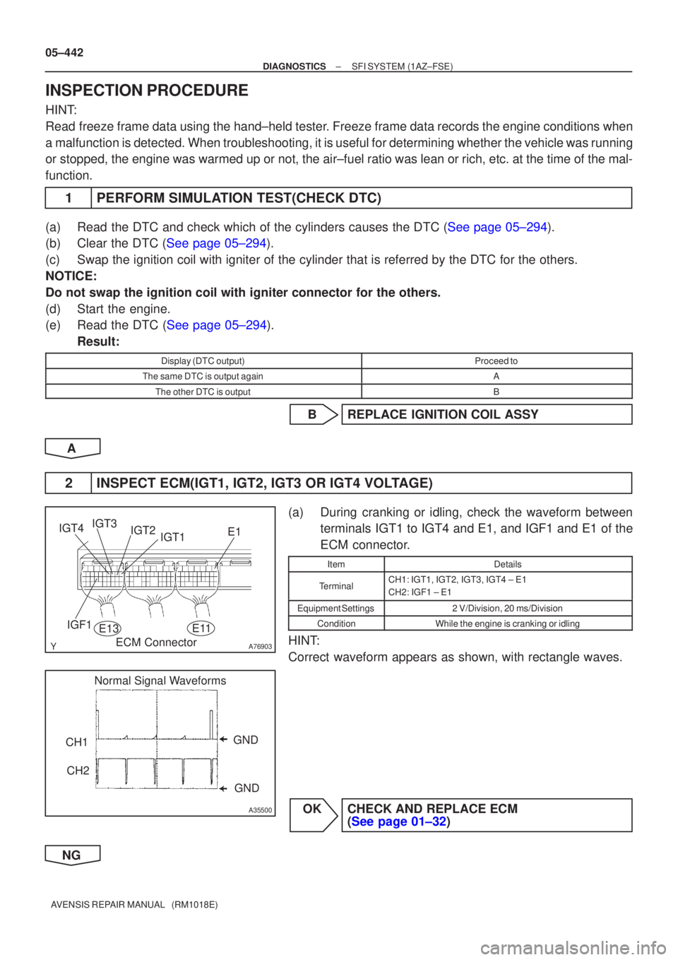
2INSPECT ECM(IGT1, IGT2, IGT3 OR IGT4 VOLTAGE)
(a)During cranking or idling, check the waveform between terminals IGT1 to IGT4 and E1, and IGF1 and E1 of the
ECM connector.
ItemDetails
TerminalCH1: IGT1, IGT2, IGT3, IGT4 ± E1
CH2: IGF1 ± E1
Equipment Settings2 V/Division, 20 ms/Division
ConditionWhile the engine is cranking or idling
HINT:
Correct waveform appears as shown, with rectangle waves.
OKCHECK AND REPLACE ECM (See page 01±32)
NG