Page 1534 of 5135
I34627
C11±21 (IG1+)
*3:
C11±10 (AUTO LEVELING)
C11±22 (IG2+)
C11±8 (AIR BAG)
C10±8 (Rr FOG)
C10±7 (Fr FOG) BUZZER
WATER LVL
CHECK E/G
VSC
SLIP
AUTO LVL
ABS
EMPS
BRAKE
A/B ACTIVE
CIRCUIT
E/G OIL LVL
FUEL
A/T OIL TEMP
CHG
ECT SNOW
D±SEAT BELT
Rr FOG
Fr FOG
TRC OFF
OIL/P
*1: GLOW
CRUISE AIR BAG
ABS ACTIVE
CIRCUIT
EMPS ACTIVE
CIRCUIT
BRAKE ACTIVE
CIRCUIT
C11±11 (OIL PRESS SW)
C11±4 (EBD) *3: C11±6 (EMPS)C10±9 (ABS) *1, 2: C11±15 (SLIP)*1, 2: C11±16 (VSC)
C11±2 (BRAKE LVL SW)
CPU
*1: 1CD±FTV, *2: 1AZ±FSE, 2AZ±FSE, *3: 1ZZ±FE, 3ZZ±FE
C11±9 (CHECK ENGINE)
*1, 2:
C11±17 (TRC OFF) 05±1504
± DIAGNOSTICSCOMBINATION METER
AVENSIS REPAIR MANUAL (RM1018E)
Page 1535 of 5135
Terminal No.
Wire harness side
Turn Signal Flasher Relay
Skid Control ECU with Actuator Brake Fluid Level Warning Switch
Engine ECU
Oil Pressure Switch
DOME Fuse Headlight Beam Level Control ECU
Skid Control ECU with Actuator
Skid Control ECU with Actuator Turn Signal Flasher Relay Engine ECU ± Multi Display RAD No.1 Fuse
GND
EMPS ECU
TAIL Fuse
Skid Control ECU with Actuator Fuel Sensor Gauge
Skid Control ECU with Actuator
± GND
Rear Fog Light Relay Front Fog Light Relay Multi Display Fuse Filter Warning Switch (*1)
IGN Fuse Fuel Sender Gauge
Engine Oil Level Sensor Security ECU Ambient Temp. Sensor
4P OUT (Other Parts) H±HI RH Fuse/H±LP RH Fuse 1
2
3
4
5
6
7
8
9
10
11
12
13
14
15
16
17
18
19
201
2
3
4
5
6
7
8
9
10
11
12
13
14
15
16
17
18
C10
Airbag Sensor Assembly GND
GAUGE1 Fuse Skid Control ECU with Actuator
C11Engine ECU
Integration Relay
21
22
*1: 1CD±FTVAmbient Temp. Sensor
± DIAGNOSTICSCOMBINATION METER
05±1505
AVENSIS REPAIR MANUAL (RM1018E)
Page 1632 of 5135

05B0B±02
B65593
I12
B55023
GND
± DIAGNOSTICSENGINE IMMOBILISER SYSTEM
05±1607
AVENSIS REPAIR MANUAL (RM1018E)
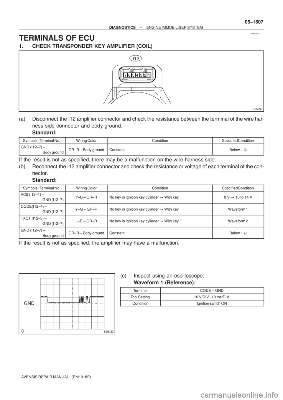
TERMINALS OF ECU
1. CHECK TRANSPONDER KEY AMPLIFIER (COIL)
(a) Disconnect the I12 amplifier connector and check the resistance between the terminal of the wire har-
ness side connector and body ground.
Standard:
Symbols (Terminal No.)Wiring ColorConditionSpecified Condition
GND (I12±7) ±
Body groundGR±R ± Body groundConstantBelow 1 �
If the result is not as specified, there may be a malfunction on the wire harness side.
(b) Reconnect the I12 amplifier connector and check the resistance or voltage of each terminal of the con-
nector.
Standard:
Symbols (Terminal No.)Wiring ColorConditionSpecified Condition
VC5 (I12±1) ±
GND (I12±7)Y±B ± GR±RNo key in ignition key cylinder � With key0 V �10 to 14 V
CODE(I12±4) ±
GND (I12±7)Y±G ± GR±RNo key in ignition key cylinder � With keyWaveform 1
TXCT (I12±5) ±
GND (I12±7)L±R ± GR±RNo key in ignition key cylinder � With keyWaveform 2
GND (I12±7) ±
Body groundGR±R ± Body groundConstantBelow 1 �
If the result is not as specified, the amplifier may have a malfunction.
(c) Inspect using an oscilloscope.
Waveform 1 (Reference):
TerminalCODE ± GND
Tool Setting10 V/DIV., 10 ms/DIV.
ConditionIgnition switch ON
Page 1637 of 5135
054CM±07
B65753
Transponder Key ECU Assy
ECM
Security Indicator
Transponder Key Amplifier
(Transponder Key Coil)
Unlock Warning Switch Assy
Transponder Key ECU Assy
Transponder Key Amplifier
(Transponder Key Coil)
Unlock Warning Switch Assy
ECM
Driver Side R/B Assy
Passenger Side R/B Assy
Center J/B
LHD Models
RHD Models 05±1606
± DIAGNOSTICSENGINE IMMOBILISER SYSTEM
AVENSIS REPAIR MANUAL (RM1018E)
LOCATION
Page 1638 of 5135

054CI±07
±
DIAGNOSTICS ENGINE IMMOBILISER SYSTEM
05±1605
AVENSIS REPAIR MANUAL (RM1018E)
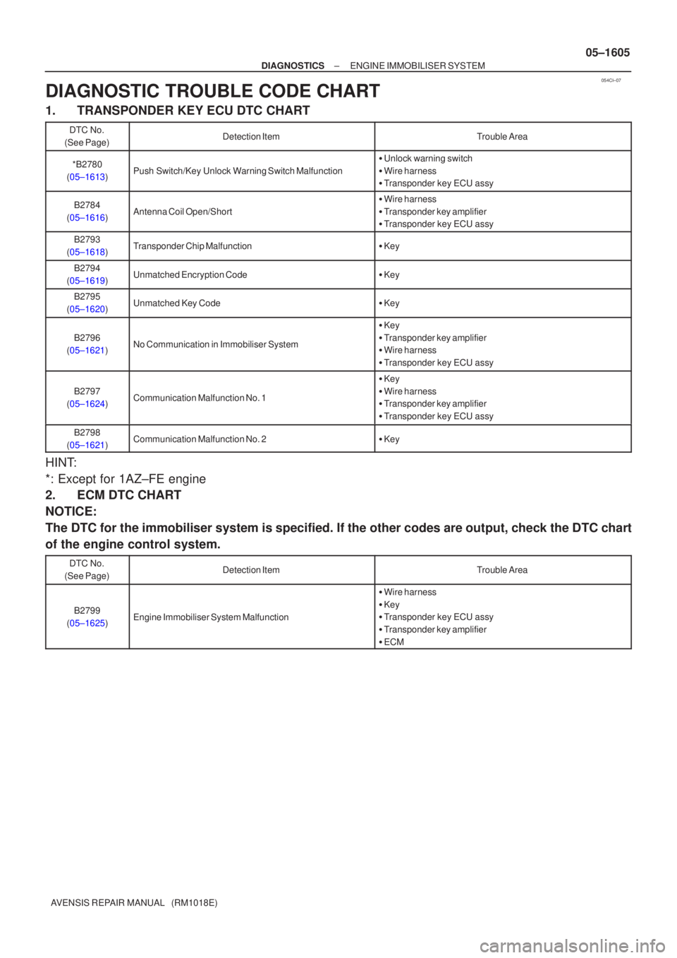
DIAGNOSTIC TROUBLE CODE CHART
1. TRANSPONDER KEY ECU DTC CHART
DTC No.
(See Page)Detection ItemTrouble Area
*B2780
(05±1613)Push Switch/Key Unlock Warning Switch Malfunction
� Unlock warning switch
� Wire harness
� Transponder key ECU assy
B2784
(05±1616)Antenna Coil Open/Short
� Wire harness
� Transponder key amplifier
� Transponder key ECU assy
B2793
(05±1618)Transponder Chip Malfunction� Key
B2794
(05±1619)Unmatched Encryption Code� Key
B2795
(05±1620)Unmatched Key Code� Key
B2796
(05±1621)No Communication in Immobiliser System
� Key
� Transponder key amplifier
� Wire harness
� Transponder key ECU assy
B2797
(05±1624)Communication Malfunction No. 1
� Key
� Wire harness
� Transponder key amplifier
� Transponder key ECU assy
B2798
(05±1621)Communication Malfunction No. 2� Key
HINT:
*: Except for 1AZ±FE engine
2. ECM DTC CHART
NOTICE:
The DTC for the immobiliser system is specified. If the other codes are out\
put, check the DTC chart
of the engine control system.
DTC No.
(See Page)Detection ItemTrouble Area
B2799
(05±1625)Engine Immobiliser System Malfunction
� Wire harness
� Key
� Transponder key ECU assy
� Transponder key amplifier
� ECM
Page 1641 of 5135
05±1604
± DIAGNOSTICSENGINE IMMOBILISER SYSTEM
AVENSIS REPAIR MANUAL (RM1018E)ItemNormal Condition Measurement Item/
Display (Range)
REG CODE SPACE
Memory space for key codes
registration/
NOT FUL or FULLNOT FUL: Possible to resister more key code
FULL: Impossible to register key code any more
ANTENNA COILAntenna coil condition/
NORMAL or FAILNormal: Antenna coil is normal
FAIL: Antenna coil is abnormal
5. ACTIVE TEST
HINT:
Performing the ACTIVE TEST using the hand±held tester allows you to operate the relay, VSV, actuator,
etc. without parts removal. Performing the ACTIVE TEST as the first step of troubleshooting is one way to
shorten the labor time.
(a) Connect the hand±held tester to the DLC3.
(b) Turn the ignition switch ON.
(c) Perform the ACTIVE TEST, according to the display on the tester.
Transponder key ECU:
ItemTest Details
SECURITY INDICTurn security indicator ON/OFF
Page 1678 of 5135
B62676
I12
Transponder Key AmplifierT8
Transponder Key ECU Assy
VC5
CODE
TXCT
AGND Y±B
Y±G
L±R
GR±R8
11
12
13 1
4
5
7 TXCT
GND
ANT2 ANT1 VC5
CODE
CoilAmplifier
± DIAGNOSTICSENGINE IMMOBILISER SYSTEM
05±1621
AVENSIS REPAIR MANUAL (RM1018E)
DTC B2796 NO COMMUNICATION IN IMMOBILISER
SYSTEM
DTC B2798 COMMUNICATION MALFUNCTION NO.2
CIRCUIT DESCRIPTION
This code is stored in the memory when a key that does not have a transponder chip is inserted or if commu-
nication between the key and transponder key ECU is impossible.
DTC No.DTC Detection ConditionTrouble Area
B2796No communication
�Key
�Wire harness
�Transponder key amplifier (Transponder key coil)
�Transponder key ECU assy
B2798Communication error�Key
WIRING DIAGRAM
05B0H±03
Page 1679 of 5135

05±1622
± DIAGNOSTICSENGINE IMMOBILISER SYSTEM
AVENSIS REPAIR MANUAL (RM1018E)
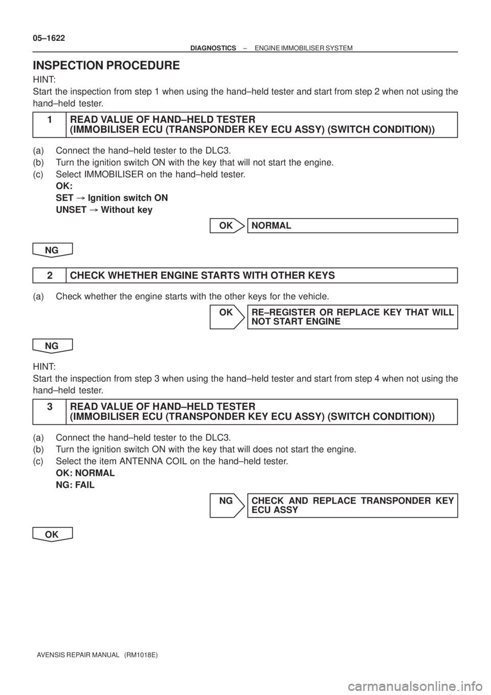
INSPECTION PROCEDURE
HINT:
Start the inspection from step 1 when using the hand±held tester and start from step 2 when not using the
hand±held tester.
1 READ VALUE OF HAND±HELD TESTER
(IMMOBILISER ECU (TRANSPONDER KEY ECU ASSY) (SWITCH CONDITION))
(a) Connect the hand±held tester to the DLC3.
(b) Turn the ignition switch ON with the key that will not start the engine.
(c) Select IMMOBILISER on the hand±held tester.
OK:
SET � Ignition switch ON
UNSET � Without key
OK NORMAL
NG
2 CHECK WHETHER ENGINE STARTS WITH OTHER KEYS
(a) Check whether the engine starts with the other keys for the vehicle.
OK RE±REGISTER OR REPLACE KEY THAT WILL
NOT START ENGINE
NG
HINT:
Start the inspection from step 3 when using the hand±held tester and start from step 4 when not using the
hand±held tester.
3 READ VALUE OF HAND±HELD TESTER
(IMMOBILISER ECU (TRANSPONDER KEY ECU ASSY) (SWITCH CONDITION))
(a) Connect the hand±held tester to the DLC3.
(b) Turn the ignition switch ON with the key that will does not start the engine.
(c) Select the item ANTENNA COIL on the hand±held tester.
OK: NORMAL
NG: FAIL
NG CHECK AND REPLACE TRANSPONDER KEY
ECU ASSY
OK