Page 1892 of 5135

A77913
Turn
Push
A77914
Turn
A81621
Fuel Pipe
Clamp
Push
11±28
±
FUEL FUEL INJECTOR ASSY(1AZ±FE)
AVENSIS REPAIR MANUAL (RM1018E)
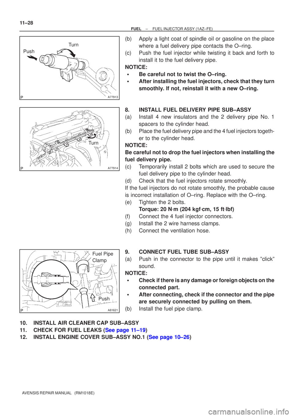
(b)Apply a light coat of spindle oil or gasoline on the place where a fuel delivery pipe contacts the O±ring.
(c)Push the fuel injector while twisting it back and forth to
install it to the fuel delivery pipe.
NOTICE:
�Be careful not to twist the O±ring.
�After installing the fuel injectors, check that they turn
smoothly. If not, reinstall it with a new O±ring.
8.INSTALL FUEL DELIVERY PIPE SUB±ASSY
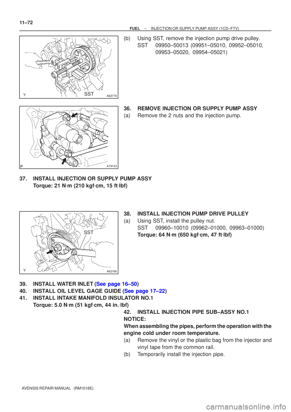
(a)Install 4 new insulators and the 2 delivery pipe No. 1 spacers to the cylinder head.
(b)Place the fuel delivery pipe and the 4 fuel injectors togeth- er to the cylinder head.
NOTICE:
Be careful not to drop the fuel injectors when installing the
fuel delivery pipe.
(c)Temporarily install 2 bolts which are used to secure the fuel delivery pipe to the cylinder head.
(d)Check that the fuel injectors rotate smoothly.
If the fuel injectors do not rotate smoothly, the probable cause
is incorrect installation of O±ring. Replace with the O±ring.
(e)Tighten the 2 bolts. Torque: 20 N �m (204 kgf �cm, 15 ft �lbf)
(f)Connect the 4 fuel injector connectors.
(g)Install the 2 wire harness clamps.
(h)Connect the ventilation hose.
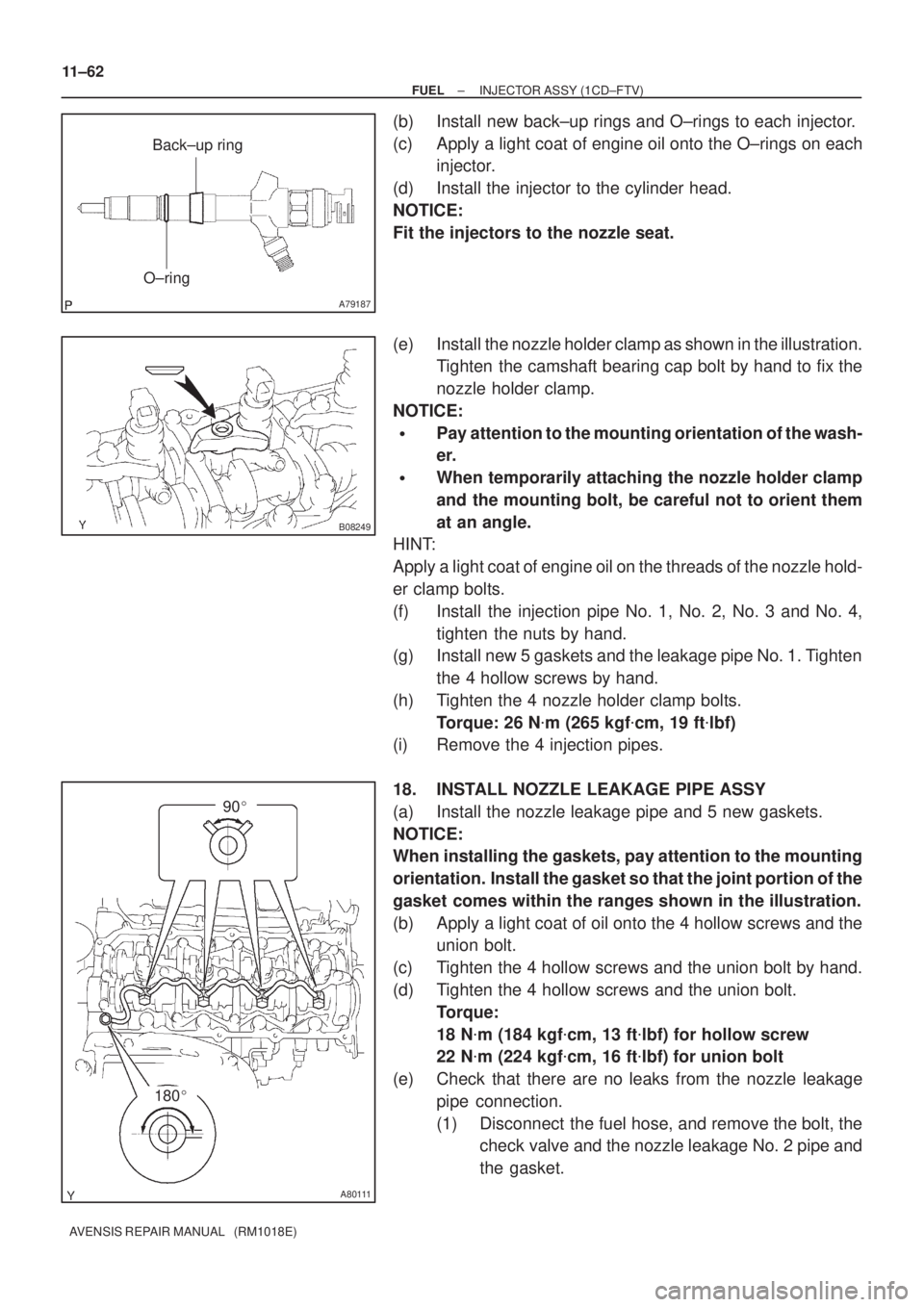
9.CONNECT FUEL TUBE SUB±ASSY
(a)Push in the connector to the pipe until it makes ºclickº sound.
NOTICE:
�Check if there is any damage or foreign objects on the
connected part.
�After connecting, check if the connector and the pipe
are securely connected by pulling on them.
(b)Install the fuel pipe clamp.
10.INSTALL AIR CLEANER CAP SUB±ASSY
11.CHECK FOR FUEL LEAKS (See page 11±19)
12.INSTALL ENGINE COVER SUB±ASSY NO.1 (See page 10±26)
Page 1912 of 5135
A79150
A79151
A79152
A62166
SST
±
FUEL INJECTION OR SUPPLY PUMP ASSY(1CD±FTV)
11±71
AVENSIS REPAIR MANUAL (RM1018E)
29.REMOVE INTAKE MANIFOLD INSULATOR NO.1
(a)Remove the 2 bolts and the intake manifold insulator.
30.REMOVE OIL LEVEL GAGE SUB±ASSY
31.REMOVE OIL LEVEL GAGE GUIDE(See page 17±22)
32.REMOVE WATER INLET(See page 16±50) 33. DISCONNECT INJECTION PUMP TO FUEL PIPE FUELHOSE
(a) Disconnect the injection pump to fuel pipe fuel hose from the supply pump.
34. DISCONNECT INJECTION PUMP TO FUEL FILTER FUEL HOSE OR PIPE
(a) Disconnect the injection pump to fuel filter fuel hose or pipe from the supply pump.
35. REMOVE INJECTION PUMP DRIVE PULLEY
(a) Using SST, remove the pulley nut. SST 09960±10010 (09962±01000, 09963±01000)
Page 1913 of 5135

A62779SST
A79153
A62166
SST
11±72
±
FUEL INJECTION OR SUPPLY PUMP ASSY(1CD±FTV)
AVENSIS REPAIR MANUAL (RM1018E)
(b)Using SST, remove the injection pump drive pulley. SST09950±50013 (09951±05010, 09952±05010, 09953±05020, 09954±05021)
36.REMOVE INJECTION OR SUPPLY PUMP ASSY
(a)Remove the 2 nuts and the injection pump.
37.INSTALL INJECTION OR SUPPLY PUMP ASSY Torque: 21 N �m (210 kgf �cm, 15 ft �lbf)
38.INSTALL INJECTION PUMP DRIVE PULLEY
(a)Using SST, install the pulley nut. SST09960±10010 (09962±01000, 09963±01000)
Torque: 64 N �m (650 kgf �cm, 47 ft �lbf)
39.INSTALL WATER INLET(See page 16±50)
40.INSTALL OIL LEVEL GAGE GUIDE(See page 17±22)
41. INSTALL INTAKE MANIFOLD INSULATOR NO.1 Torque: 5.0 N �m (51 kgf �cm, 44 in. �lbf)
42. INSTALL INJECTION PIPE SUB±ASSY NO.1
NOTICE:
When assembling the pipes, perform the operation with the
engine cold under room temperature.
(a) Remove the vinyl or the plastic bag from the injector and vinyl tape from the common rail.
(b) Temporarily install the injection pipe.
Page 1919 of 5135
A79436
5.0 (51, 44 in.�lbf)
* 42 (428, 31)
46 (469, 34)
* 31 (316, 23)
34 (347, 25)
* 31 (316, 23)
34 (347, 25)
Injection Pipe Clamp No. 2
Injection Pipe Sub±assy
� Fuel Inlet Pipe Sub±assy
64 (650, 47)
Injection Pump
Drive Pulley
� O±ring Oil Level Gage Guide
: Specified torqueN´m (kgf´cm, ft´lbf)
* Use SST
18 (184, 13)
Oil Level Gage Sub±assy Injection or
Supply Pump Assy
21 (210, 15)
21 (210, 15)
Water Inlet
8.8 (90, 78 in.�lbf)
� Gasket
5.0 (51, 44 in.�lbf)
Intake Manifold
Insulator No. 1
* 42 (428, 31)
46 (469, 34)
Injection Pump to Fuel Filter
Fuel Hose or Pipe
Injection Pump to Fuel Pipe
Fuel Hose
11±68
± FUELINJECTION OR SUPPLY PUMP ASSY (1CD±FTV)
AVENSIS REPAIR MANUAL (RM1018E)
Page 1922 of 5135

A79187
O±ringBack±up ring
B08249
A80111
180�
90� 11±62
± FUELINJECTOR ASSY (1CD±FTV)
AVENSIS REPAIR MANUAL (RM1018E)
(b) Install new back±up rings and O±rings to each injector.
(c) Apply a light coat of engine oil onto the O±rings on each
injector.
(d) Install the injector to the cylinder head.
NOTICE:
Fit the injectors to the nozzle seat.
(e) Install the nozzle holder clamp as shown in the illustration.
Tighten the camshaft bearing cap bolt by hand to fix the
nozzle holder clamp.
NOTICE:
�Pay attention to the mounting orientation of the wash-
er.
�When temporarily attaching the nozzle holder clamp
and the mounting bolt, be careful not to orient them
at an angle.
HINT:
Apply a light coat of engine oil on the threads of the nozzle hold-
er clamp bolts.
(f) Install the injection pipe No. 1, No. 2, No. 3 and No. 4,
tighten the nuts by hand.
(g) Install new 5 gaskets and the leakage pipe No. 1. Tighten
the 4 hollow screws by hand.
(h) Tighten the 4 nozzle holder clamp bolts.
Torque: 26 N�m (265 kgf�cm, 19 ft�lbf)
(i) Remove the 4 injection pipes.
18. INSTALL NOZZLE LEAKAGE PIPE ASSY
(a) Install the nozzle leakage pipe and 5 new gaskets.
NOTICE:
When installing the gaskets, pay attention to the mounting
orientation. Install the gasket so that the joint portion of the
gasket comes within the ranges shown in the illustration.
(b) Apply a light coat of oil onto the 4 hollow screws and the
union bolt.
(c) Tighten the 4 hollow screws and the union bolt by hand.
(d) Tighten the 4 hollow screws and the union bolt.
Torque:
18 N�m (184 kgf�cm, 13 ft�lbf) for hollow screw
22 N�m (224 kgf�cm, 16 ft�lbf) for union bolt
(e) Check that there are no leaks from the nozzle leakage
pipe connection.
(1) Disconnect the fuel hose, and remove the bolt, the
check valve and the nozzle leakage No. 2 pipe and
the gasket.
Page 1931 of 5135

A79573
A79574
A79834
± FUELFUEL PUMP ASSY (1AZ±FSE)
11±53
AVENSIS REPAIR MANUAL (RM1018E)
(c) Remove the 2 bolts first, then remove the fuel pipe sub±
assy No. 1 from the fuel delivery pipe sub±assy.
NOTICE:
Be careful not to damage both the sealing surfaces of the
fuel delivery pipe and the fuel pump when removing the
fuel pipe No.1.
8. REMOVE FUEL PUMP ASSY
(a) Disconnect the fuel pump assy connector.
(b) Remove the 2 nuts and the fuel pump assy.
(c) Remove the fuel pump insulator.
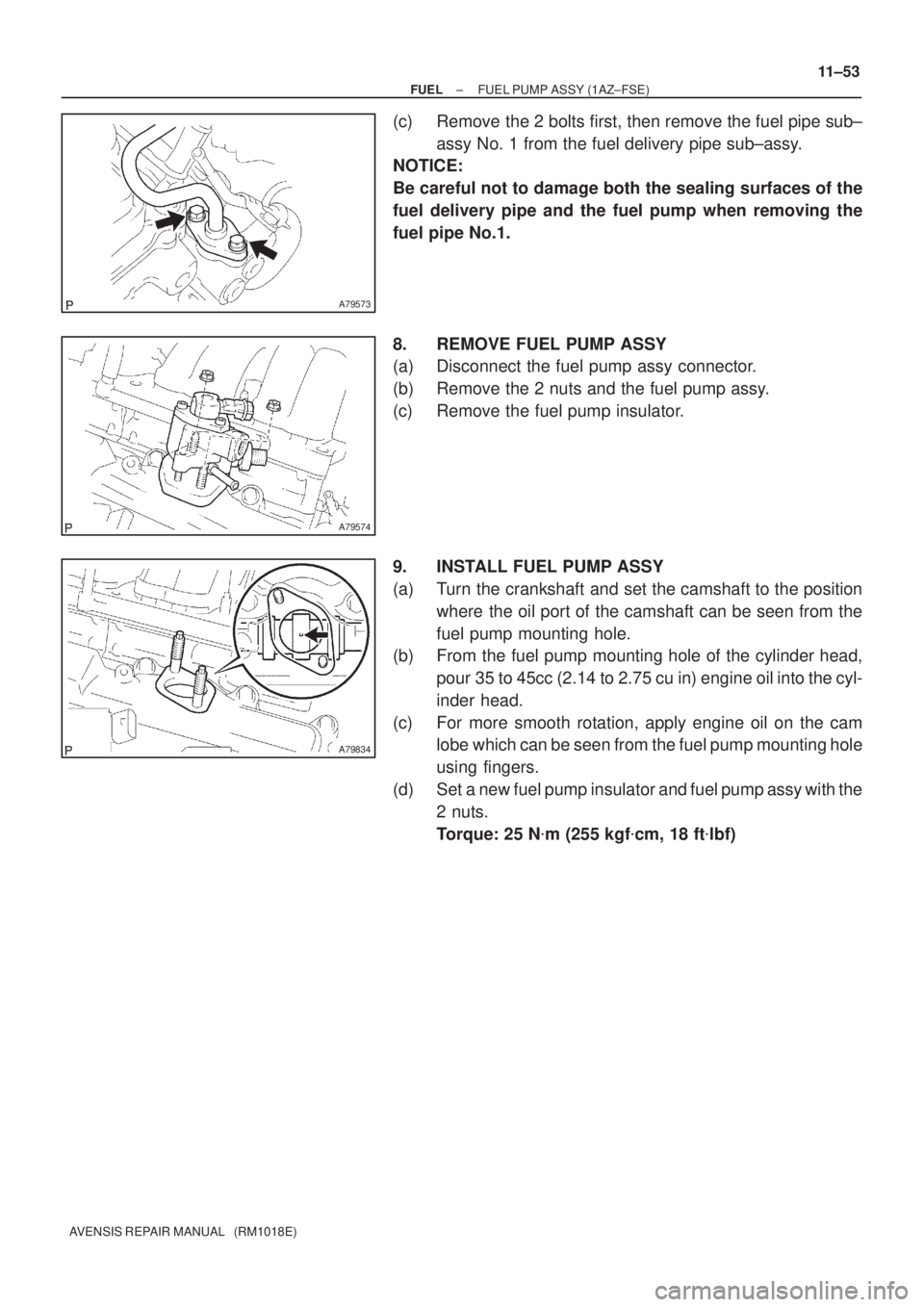
9. INSTALL FUEL PUMP ASSY
(a) Turn the crankshaft and set the camshaft to the position
where the oil port of the camshaft can be seen from the
fuel pump mounting hole.
(b) From the fuel pump mounting hole of the cylinder head,
pour 35 to 45cc (2.14 to 2.75 cu in) engine oil into the cyl-
inder head.
(c) For more smooth rotation, apply engine oil on the cam
lobe which can be seen from the fuel pump mounting hole
using fingers.
(d) Set a new fuel pump insulator and fuel pump assy with the
2 nuts.
Torque: 25 N�m (255 kgf�cm, 18 ft�lbf)
Page 1934 of 5135
1203V±03
B08075
12±16
± EMISSION CONTROLEMISSION CONTROL SYSTEM (1CD±FTV)
AVENSIS REPAIR MANUAL (RM1018E)
EMISSION CONTROL SYSTEM (1CD±FTV)
ON±VEHICLE INSPECTION
1. VISUALLY INSPECT HOSES, CONNECTIONS AND
GASKETS
(a) Check for cracks, leak or damage.
HINT:
Separation of the engine oil dipstick, oil filler cap, PCV hose,
etc. may cause the engine to run improperly. Disconnection,
looseness or cracks in the parts of the air induction system be-
tween the throttle body and cylinder head will allow air suction
and cause the engine to run improperly.
Page 1949 of 5135
A62836
1ZZ±FE
3ZZ±FE
12±2
± EMISSION CONTROLEMISSION CONTROL SYSTEM (1ZZ±FE/3ZZ±FE)
AVENSIS REPAIR MANUAL (RM1018E)
4. VISUALLY INSPECT HOSES, CONNECTIONS AND
GASKETS
(a) Check for cracks, leaks or damage.
HINT:
Separation of the engine oil dipstick, oil filler cap, PCV hose,
etc. may cause the engine to run improperly. Disconnection,
looseness or cracks in the parts of the air induction system be-
tween the throttle body and cylinder head will allow air suction
and cause the engine to run improperly.