Page 1996 of 5135
B13096
A79165
B
BAA
± INTAKETURBOCHARGER SUB±ASSY (1CD±FTV)
13±15
AVENSIS REPAIR MANUAL (RM1018E)
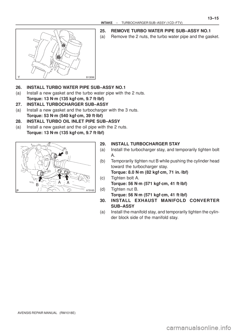
25. REMOVE TURBO WATER PIPE SUB±ASSY NO.1
(a) Remove the 2 nuts, the turbo water pipe and the gasket.
26. INSTALL TURBO WATER PIPE SUB±ASSY NO.1
(a) Install a new gasket and the turbo water pipe with the 2 nuts.
Torque: 13 N�m (135 kgf�cm, 9.7 ft�lbf)
27. INSTALL TURBOCHARGER SUB±ASSY
(a) Install a new gasket and the turbocharger with the 3 nuts.
Torque: 53 N�m (540 kgf�cm, 39 ft�lbf)
28. INSTALL TURBO OIL INLET PIPE SUB±ASSY
(a) Install a new gasket and the oil pipe with the 2 nuts.
Torque: 13 N�m (135 kgf�cm, 9.7 ft�lbf)
29. INSTALL TURBOCHARGER STAY
(a) Install the turbocharger stay, and temporarily tighten bolt
A.
(b) Temporarily tighten nut B while pushing the cylinder head
toward the turbocharger stay.
Torque: 8.0 N�m (82 kgf�cm, 71 in.�lbf)
(c) Tighten bolt A.
Torque: 56 N�m (571 kgf�cm, 41 ft�lbf)
(d) Tighten nut B.
Torque: 56 N�m (571 kgf�cm, 41 ft�lbf)
30. INSTALL EXHAUST MANIFOLD CONVERTER
SUB±ASSY
(a) Install the manifold stay, and temporarily tighten the cylin-
der block side of the manifold stay.
Page 1998 of 5135
A64328
2 to 7 mm0 to 2 mm
A78274
Upward90�
Clamp
Bolt
±
INTAKE TURBOCHARGER SUB±ASSY(1CD±FTV)
13±17
AVENSIS REPAIR MANUAL (RM1018E)
41.INSTALL INTERCOOLER AIR HOSE
(a)Install the air hose and hose clamps as shown in the il-
lustration.
(b)Tighten the hose clamps as shown in the illustration. Torque: 6.0 N �m (61 kgf �cm, 53 in. �lbf)
(c)Install the air tube No. 1 with the 3 bolts and nut. Torque: 25 N �m (255 kgf �cm, 18 ft �lbf)
42.INSTALL AIR CLEANER ASSY Torque: 7.0 N �m (71 kgf �cm, 62 in. �lbf)
43.INSTALL VACUUM RESERVOIR SUB±ASSY Torque: 8.3 N �m (85 kgf �cm, 73 in. �lbf)
44.INSTALL ENGINE COVER NO.1
Torque: 8.0 N �m (82 kgf �cm, 71 in. �lbf)
45.ADD ENGINE COOLANT(See page 16±44)
46. CHECK ENGINE OIL LEVEL
47.CHECK FOR ENGINE COOLANT LEAKS(See page 16±44)
48. CHECK FOR ENGINE OIL LEAKS
49.CHECK FOR FUEL LEAKS(See page 11±60)
50. CHECK FOR EXHAUST GAS LEAKS
Page 2001 of 5135
A79441
N´m (kgf´cm, ft´lbf)
: Specified torque
� Non±reusable part� Gasket
� Gasket � Gasket
20 (204, 15)
20 (204, 15)
20 (204, 15)
12 (122, 8.9)
53 (540, 39)
13 (135, 9.7)
36 (367, 27)
61 (622, 45)
56 (571, 41)
25 (255, 18)
Turbo Insulator No. 1
Exhaust Manifold Heat Insulator No. 2
Turbocharger Stay
Turbocharger Sub±assy
Turbo Oil Inlet Pipe
Sub±assy
Manifold Stay Manifold Stay No. 2
Exhaust Manifold
Converter Sub±assy Turbo Insulator No. 2
Turbo Water Pipe
Sub±assy No. 1
13 (135, 9.7)
56 (571, 41)
Turbo Water
Hose No. 2
Turbo Water
Hose No. 1
� Gasket
12 (122, 8.9)
� 13±10
± INTAKETURBOCHARGER SUB±ASSY (1CD±FTV)
AVENSIS REPAIR MANUAL (RM1018E)
Page 2005 of 5135
1302Y±03
A77119
A77120
A77121
± INTAKETURBO CHARGER SYSTEM (1CD±FTV)
13±3
AVENSIS REPAIR MANUAL (RM1018E)
TURBO CHARGER SYSTEM (1CD±FTV)
PRECAUTION
1. MAINTENANCE PRECAUTION
(a) Do not stop the engine immediately after pulling a trailer,
or after driving at a high speed, or uphill drive. Let the en-
gine Idle for 20 to 120 seconds before turn the ignition
switch OFF (According as the driving condition, the idling
time varies).
(b) Avoid quick acceleration or quickly accelerating the en-
gine RPM immediately after the starting a cold engine.
(c) If the turbocharger is found to be defective, it must be re-
placed. Also, inspect a source of the trouble including
conditions of the turbocharger that having been used. Re-
pair or replace the followings as necessary:
(1) Engine oil (Level and quality)
(2) Oil lines leading to the turbocharger
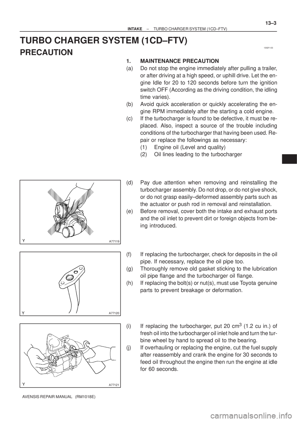
(d) Pay due attention when removing and reinstalling the
turbocharger assembly. Do not drop, or do not give shock,
or do not grasp easily±deformed assembly parts such as
the actuator or push rod in removal and reinstallation.
(e) Before removal, cover both the intake and exhaust ports
and the oil inlet to prevent dirt or foreign objects from be-
ing introduced.
(f) If replacing the turbocharger, check for deposits in the oil
pipe. If necessary, replace the oil pipe too.
(g) Thoroughly remove old gasket sticking to the lubrication
oil pipe flange and the turbocharger oil flange.
(h) If replacing the bolt(s) or nut(s), must use Toyota genuine
parts to prevent breakage or deformation.
(i) If replacing the turbocharger, put 20 cm
3 (1.2 cu in.) of
fresh oil into the turbocharger oil inlet hole and turn the tur-
bine wheel by hand to spread oil to the bearing.
(j) If overhauling or replacing the engine, cut the fuel supply
after reassembly and crank the engine for 30 seconds to
feed oil throughout the engine then run the engine at idle
for 60 seconds.
Page 2012 of 5135
141CK±01
A78459
A76713
A64023
A65078
14±64
±
ENGINE MECHANICAL CAMSHAFT(1ZZ±FE/3ZZ±FE)
AVENSIS REPAIR MANUAL (RM1018E)
REPLACEMENT
1.REMOVE RADIATOR SUPPORT OPENING COVER (See page 14±27)
2.REMOVE ENGINE UNDER COVER RH (See page 14±27) 3. REMOVE CYLINDER HEAD COVER NO.2
(a) Remove and the 2 screw and 2 clips and detach the en-gine under cover No.2.
4. DISCONNECT COIL, IGNITION
(a) Remove the 5 clamps from the 5 clamp brackets.
(b) Disconnect the 4 ignition coil connectors.
(c) Remove the 2 nuts which are used to secure the engine wire.
(d) Remove the 4 bolts and the 4 ignition coils.
5. DISCONNECT VENTILATION HOSE
(a) Disconnect the ventilation hose from the cylinder head cover.
Page 2016 of 5135
A32556
A62190
Advance
Side Path Retard Side
Path
Open
Close
Rubber Vinyl Tape Open Close
A62191
Advanced
Side Path Retard
Side Path
14±68
± ENGINE MECHANICALCAMSHAFT (1ZZ±FE/3ZZ±FE)
AVENSIS REPAIR MANUAL (RM1018E)
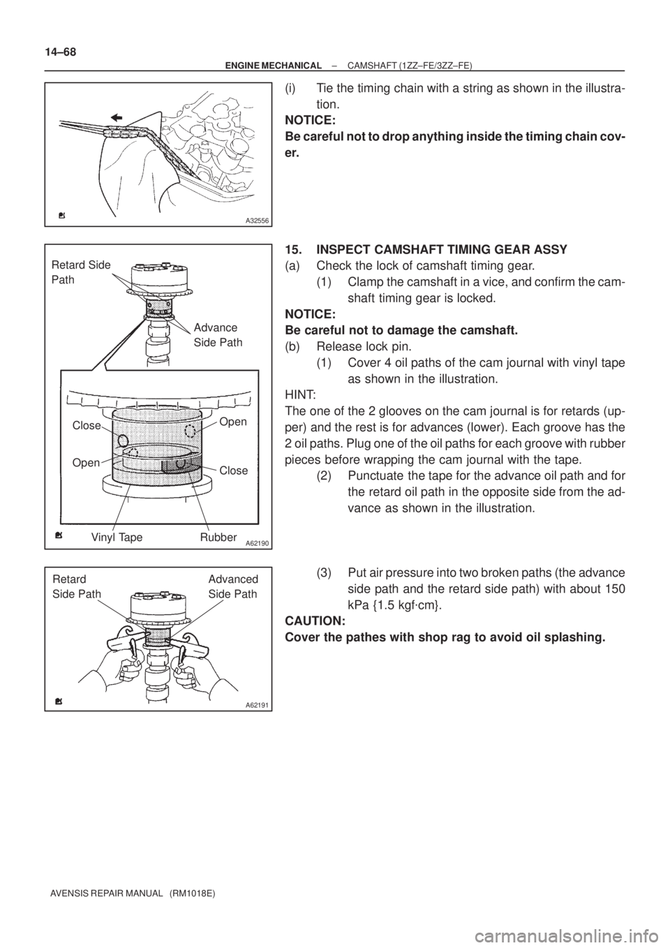
(i) Tie the timing chain with a string as shown in the illustra-
tion.
NOTICE:
Be careful not to drop anything inside the timing chain cov-
er.
15. INSPECT CAMSHAFT TIMING GEAR ASSY
(a) Check the lock of camshaft timing gear.
(1) Clamp the camshaft in a vice, and confirm the cam-
shaft timing gear is locked.
NOTICE:
Be careful not to damage the camshaft.
(b) Release lock pin.
(1) Cover 4 oil paths of the cam journal with vinyl tape
as shown in the illustration.
HINT:
The one of the 2 glooves on the cam journal is for retards (up-
per) and the rest is for advances (lower). Each groove has the
2 oil paths. Plug one of the oil paths for each groove with rubber
pieces before wrapping the cam journal with the tape.
(2) Punctuate the tape for the advance oil path and for
the retard oil path in the opposite side from the ad-
vance as shown in the illustration.
(3) Put air pressure into two broken paths (the advance
side path and the retard side path) with about 150
kPa {1.5 kgf�cm}.
CAUTION:
Cover the pathes with shop rag to avoid oil splashing.
Page 2017 of 5135
A62192
Hold Pressure
DecompressAdvanced
Side Path Retard
Side Path
A62190
Advance
Side Path Retard Side
Path
Open
Close
Rubber Vinyl Tape Open Close
± ENGINE MECHANICALCAMSHAFT (1ZZ±FE/3ZZ±FE)
14±69
AVENSIS REPAIR MANUAL (RM1018E)
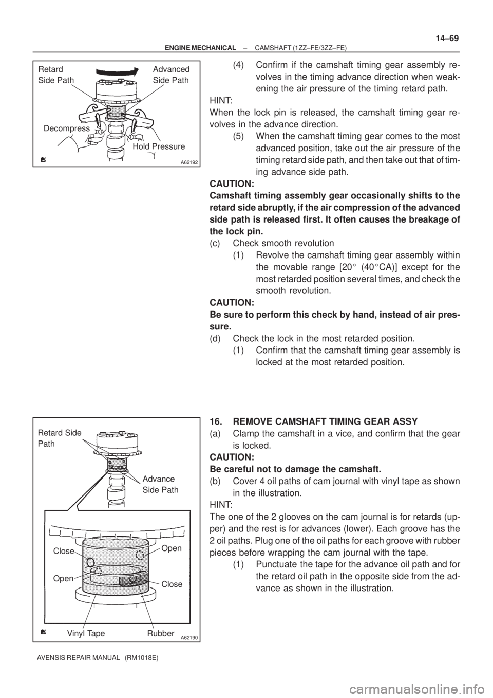
(4) Confirm if the camshaft timing gear assembly re-
volves in the timing advance direction when weak-
ening the air pressure of the timing retard path.
HINT:
When the lock pin is released, the camshaft timing gear re-
volves in the advance direction.
(5) When the camshaft timing gear comes to the most
advanced position, take out the air pressure of the
timing retard side path, and then take out that of tim-
ing advance side path.
CAUTION:
Camshaft timing assembly gear occasionally shifts to the
retard side abruptly, if the air compression of the advanced
side path is released first. It often causes the breakage of
the lock pin.
(c) Check smooth revolution
(1) Revolve the camshaft timing gear assembly within
the movable range [20� (40�CA)] except for the
most retarded position several times, and check the
smooth revolution.
CAUTION:
Be sure to perform this check by hand, instead of air pres-
sure.
(d) Check the lock in the most retarded position.
(1) Confirm that the camshaft timing gear assembly is
locked at the most retarded position.
16. REMOVE CAMSHAFT TIMING GEAR ASSY
(a) Clamp the camshaft in a vice, and confirm that the gear
is locked.
CAUTION:
Be careful not to damage the camshaft.
(b) Cover 4 oil paths of cam journal with vinyl tape as shown
in the illustration.
HINT:
The one of the 2 glooves on the cam journal is for retards (up-
per) and the rest is for advances (lower). Each groove has the
2 oil paths. Plug one of the oil paths for each groove with rubber
pieces before wrapping the cam journal with the tape.
(1) Punctuate the tape for the advance oil path and for
the retard oil path in the opposite side from the ad-
vance as shown in the illustration.
Page 2018 of 5135
A62191
Advanced
Side Path Retard
Side Path
A62192
Hold Pressure
DecompressAdvanced
Side Path Retard
Side Path
A62193
Straight Pin Fringe Bolt
A62194
Straight Pin
Key Groove
14±70
± ENGINE MECHANICALCAMSHAFT (1ZZ±FE/3ZZ±FE)
AVENSIS REPAIR MANUAL (RM1018E)
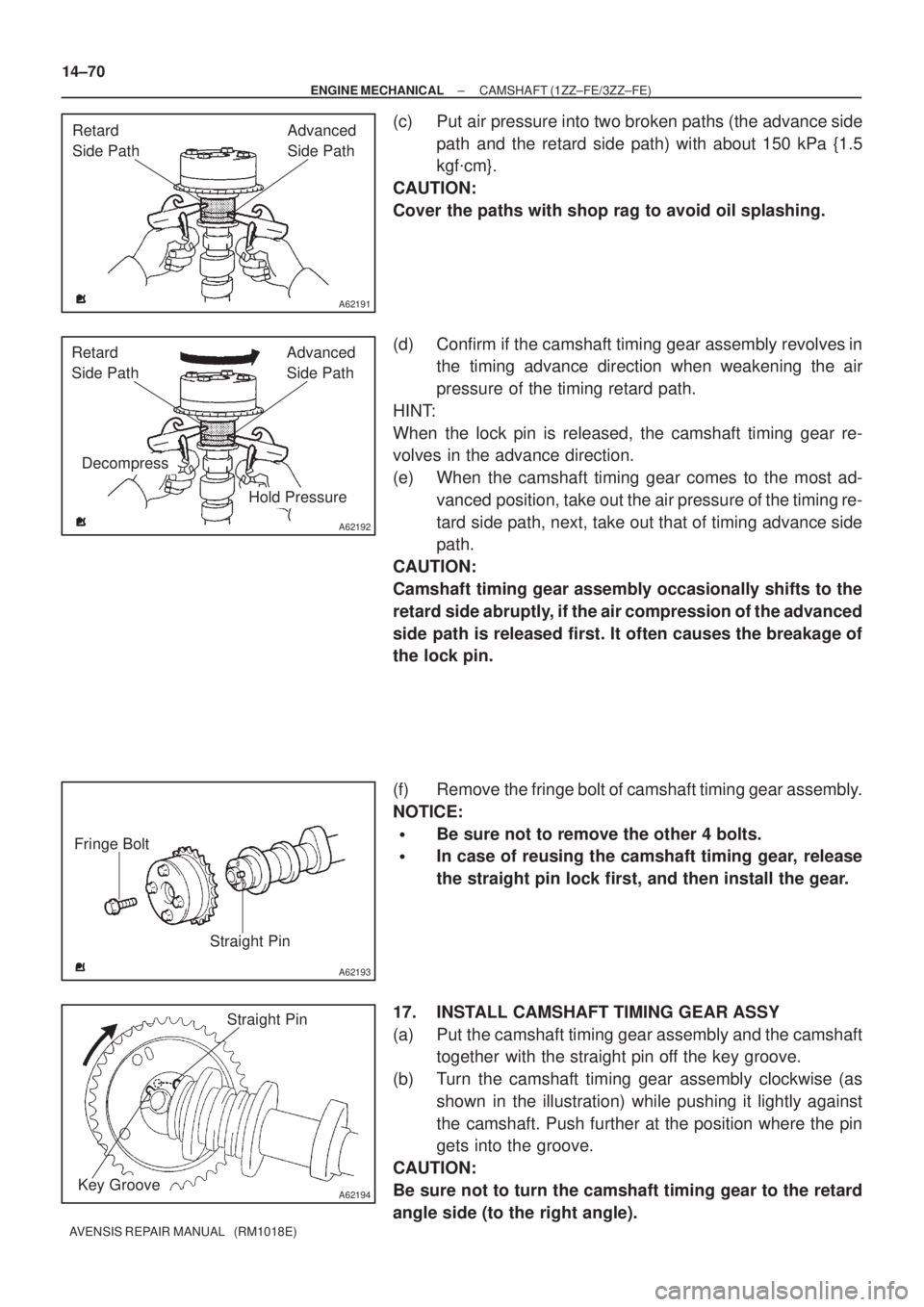
(c) Put air pressure into two broken paths (the advance side
path and the retard side path) with about 150 kPa {1.5
kgf�cm}.
CAUTION:
Cover the paths with shop rag to avoid oil splashing.
(d) Confirm if the camshaft timing gear assembly revolves in
the timing advance direction when weakening the air
pressure of the timing retard path.
HINT:
When the lock pin is released, the camshaft timing gear re-
volves in the advance direction.
(e) When the camshaft timing gear comes to the most ad-
vanced position, take out the air pressure of the timing re-
tard side path, next, take out that of timing advance side
path.
CAUTION:
Camshaft timing gear assembly occasionally shifts to the
retard side abruptly, if the air compression of the advanced
side path is released first. It often causes the breakage of
the lock pin.
(f) Remove the fringe bolt of camshaft timing gear assembly.
NOTICE:
�Be sure not to remove the other 4 bolts.
�In case of reusing the camshaft timing gear, release
the straight pin lock first, and then install the gear.
17. INSTALL CAMSHAFT TIMING GEAR ASSY
(a) Put the camshaft timing gear assembly and the camshaft
together with the straight pin off the key groove.
(b) Turn the camshaft timing gear assembly clockwise (as
shown in the illustration) while pushing it lightly against
the camshaft. Push further at the position where the pin
gets into the groove.
CAUTION:
Be sure not to turn the camshaft timing gear to the retard
angle side (to the right angle).