Page 2034 of 5135

A65676
Timing Chain Cover side:
3 (0.118)3 (0.118)
A
ABB
C
C
7 (0.276)
4.5 (0.177)
12 (0.472)6 (0.236)
3 (0.118)
Width 4 (0.157)
A ± AB ± B
C ± C
08826±00100 or equivalent
08826±00080 or equivalent
(mm (in.))
A65677
A
A
AA
A
A
AAA B
B
B
± ENGINE MECHANICALCHAIN SUB±ASSY (1ZZ±FE/3ZZ±FE)
14±55
AVENSIS REPAIR MANUAL (RM1018E)
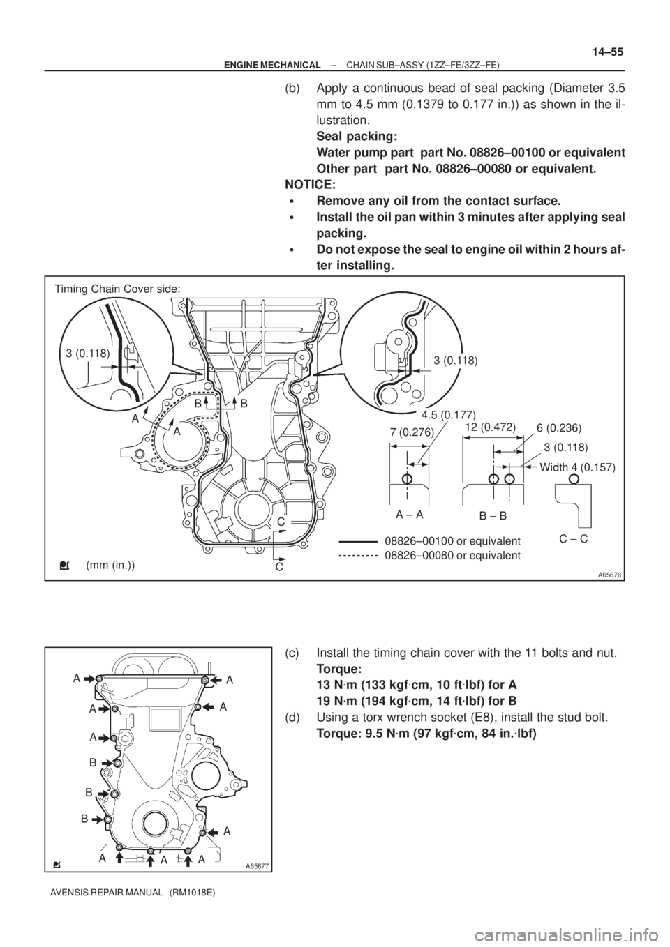
(b) Apply a continuous bead of seal packing (Diameter 3.5
mm to 4.5 mm (0.1379 to 0.177 in.)) as shown in the il-
lustration.
Seal packing:
Water pump part part No. 08826±00100 or equivalent
Other part part No. 08826±00080 or equivalent.
NOTICE:
�Remove any oil from the contact surface.
�Install the oil pan within 3 minutes after applying seal
packing.
�Do not expose the seal to engine oil within 2 hours af-
ter installing.
(c) Install the timing chain cover with the 11 bolts and nut.
Torque:
13 N�m (133 kgf�cm, 10 ft�lbf) for A
19 N�m (194 kgf�cm, 14 ft�lbf) for B
(d) Using a torx wrench socket (E8), install the stud bolt.
Torque: 9.5 N�m (97 kgf�cm, 84 in.�lbf)
Page 2035 of 5135

A62177
Raise
Push
Hook
Pin
A62178
Push
A76692
A12816
A11858
14±56
±
ENGINE MECHANICAL CHAIN SUB±ASSY(1ZZ±FE/3ZZ±FE)
AVENSIS REPAIR MANUAL (RM1018E)
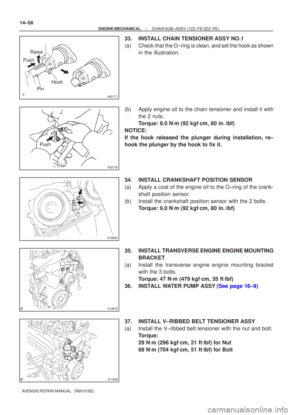
33.INSTALL CHAIN TENSIONER ASSY NO.1
(a)Check that the O±ring is clean, and set the hook as shown in the illustration.
(b)Apply engine oil to the chain tensioner and install it with the 2 nuts.
Torque: 9.0 N �m (92 kgf �cm, 80 in. �lbf)
NOTICE:
If the hook released the plunger during installation, re±
hook the plunger by the hook to fix it.
34.INSTALL CRANKSHAFT POSITION SENSOR
(a)Apply a coat of the engine oil to the O±ring of the crank- shaft position sensor.
(b)Install the crankshaft position sensor with the 2 bolts. Torque: 9.0 N �m (92 kgf �cm, 80 in. �lbf)
35.INSTALL TRANSVERSE ENGINE ENGINE MOUNTING BRACKET
(a)Install the transverse engine engine mounting bracket with the 3 bolts.
Torque: 47 N �m (479 kgf �cm, 35 ft �lbf)
36.INSTALL WATER PUMP ASSY(See page 16±9)
37. INSTALL V±RIBBED BELT TENSIONER ASSY
(a) Install the V±ribbed belt tensioner with the nut and bolt. Torque:
29 N�m (296 kgf �cm, 21 ft �lbf) for Nut
69 N �m (704 kgf �cm, 51 ft �lbf) for Bolt
Page 2036 of 5135

A62837SST
A62180
Disconnect
Hook
Pin Turn
A62181
Plunger
Turn
Push
A62182
Seal Packing
± ENGINE MECHANICALCHAIN SUB±ASSY (1ZZ±FE/3ZZ±FE)
14±57
AVENSIS REPAIR MANUAL (RM1018E)
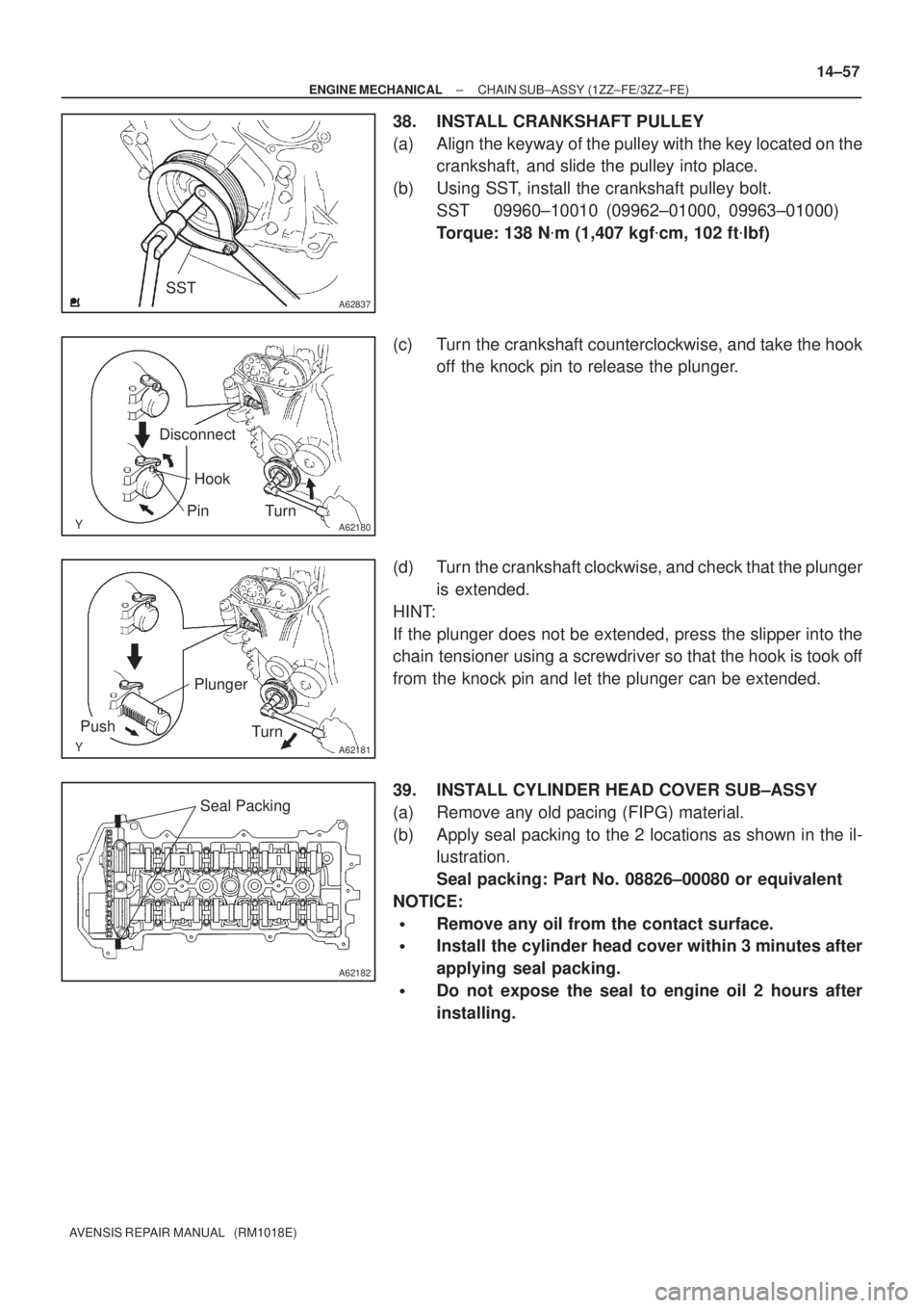
38. INSTALL CRANKSHAFT PULLEY
(a) Align the keyway of the pulley with the key located on the
crankshaft, and slide the pulley into place.
(b) Using SST, install the crankshaft pulley bolt.
SST 09960±10010 (09962±01000, 09963±01000)
Torque: 138 N�m (1,407 kgf�cm, 102 ft�lbf)
(c) Turn the crankshaft counterclockwise, and take the hook
off the knock pin to release the plunger.
(d) Turn the crankshaft clockwise, and check that the plunger
is extended.
HINT:
If the plunger does not be extended, press the slipper into the
chain tensioner using a screwdriver so that the hook is took off
from the knock pin and let the plunger can be extended.
39. INSTALL CYLINDER HEAD COVER SUB±ASSY
(a) Remove any old pacing (FIPG) material.
(b) Apply seal packing to the 2 locations as shown in the il-
lustration.
Seal packing: Part No. 08826±00080 or equivalent
NOTICE:
�Remove any oil from the contact surface.
�Install the cylinder head cover within 3 minutes after
applying seal packing.
�Do not expose the seal to engine oil 2 hours after
installing.
Page 2037 of 5135
A65687
AAA
A
A
A
A
A
A
BB
A64005
A64023
A76713
14±58
±
ENGINE MECHANICAL CHAIN SUB±ASSY(1ZZ±FE/3ZZ±FE)
AVENSIS REPAIR MANUAL (RM1018E)
(c)Install the cylinder head cover and 3 cable brackets with the 9 bolts, 2 seal washers and 2 nuts. Tighten the bolts
and nuts uniformly in the several steps.
Torque:
11 N�m (112 kgf �cm, 8 ft �lbf) for A
9.0 N �m (92 kgf �cm, 80 in. �lbf) for B
40.INSTALL ENGINE MOUNTIN G INSULATOR
SUB±ASSY RH
(a)Install the engine mounting insulator with the 4 bolts and 2 nuts.
Torque: 52 N �m (530 kgf �cm, 38 ft �lbf)
41.INSTALL IGNITION COIL ASSY
(a)Install the 4 ignition coils with the 4 bolts. Torque: 9.0 N �m (92 kgf �cm, 80 in. �lbf)
(b)Install the engine wire with the 2 nuts. Torque: 9.0 N �m (92 kgf �cm, 80 in. �lbf)
42.INSTALL GENERATOR ASSY (See page 19±7)
Page 2038 of 5135
A79324
A78459
±
ENGINE MECHANICAL CHAIN SUB±ASSY(1ZZ±FE/3ZZ±FE)
14±59
AVENSIS REPAIR MANUAL (RM1018E)
43.INSTALL V±RIBBED IDLER ASSY NO.1
(a)Install the tube and idler with the nut and bolt.
Torque: 39.2 N �m (400 kgf �cm, 29 ft �lbf)
44.INSTALL CYLINDER HEAD COVER NO.2
(a)Install the cylinder head cover with the 2 nuts and 2 clips. Torque: 7.0 N �m (71 kgf �cm, 62 in. �lbf)
45.INSTALL FRONT WHEEL RH Torque: 103 N �m (1,050 kgf �cm, 76 ft �lbf)
46.ADD ENGINE COOLANT(See page 16±7)
47.CHECK FOR ENGINE COOLANT LEAKS(See page 16±7)
48. CHECK FOR ENGINE OIL LEAKS
Page 2041 of 5135
A76709
Ventilation Hose No. 2
Clamp Bracket
Ventilation Hose Ignition Coil AssyEngine Wire
Clamp Bracket
Clamp Bracket
Gasket
Cylinder Head Cover
Sub±assy
Seal Washer
N´m (kgf´cm, ft´lbf) : Specified torque
9.0 (92, 80 in.�lbf)
9.0 (92, 80 in.�lbf)
9.0 (92, 80 in.�lbf)
9.0 (92, 80 in.�lbf)
11 (112, 8)
11 (112, 8)11 (112, 8)
11 (112, 8)
± ENGINE MECHANICALCHAIN SUB±ASSY (1ZZ±FE/3ZZ±FE)
14±47
AVENSIS REPAIR MANUAL (RM1018E)
Page 2042 of 5135
A60625
Crankshaft Pulley V±ribbed Belt
Tensioner Assy
Water Pump AssyTransverse Engine
Engine Mounting Bracket
Crankshaft Position Sensor Chain Tensioner Assy No. 1
Timing Chain or
Belt Cover Sub±assy
� Oil Seal
Crankshaft Position Sensor
Plate No. 1Chain Sub±assy
Chain Tensioner Slipper
Crankshaft timing Sprocket� O±ring
� Non±reusable part
N´m (kgf´cm, ft´lbf) : Specified torque
47 (479, 35)
29 (296, 21)
69 (704, 51)
138 (1,047, 102)
13 (133, 10)
9.0 (92, 80 in.�lbf)
9.0 (92, 80 in.�lbf)
19 (194, 14)
9.0 (92, 80 in.�lbf) (L=20)
11 (112, 8) (L=35)
9.5 (97, 84 in.�lbf)
13 (133, 10) (M6)
19 (194, 14) (M8)
14±48
± ENGINE MECHANICALCHAIN SUB±ASSY (1ZZ±FE/3ZZ±FE)
AVENSIS REPAIR MANUAL (RM1018E)
Page 2044 of 5135

A78516
A78459
14±28
±
ENGINE MECHANICAL PARTIAL ENGINE ASSY(1ZZ±FE/3ZZ±FE)
AVENSIS REPAIR MANUAL (RM1018E)
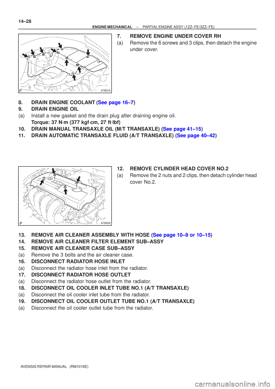
7.REMOVE ENGINE UNDER COVER RH
(a)Remove the 6 screws and 3 clips, then detach the engine under cover.
8.DRAIN ENGINE COOLANT(See page 16±7)
9. DRAIN ENGINE OIL
(a) Install a new gasket and the drain plug after draining engine oil. Torque: 37 N �m (377 kgf �cm, 27 ft �lbf)
10.DRAIN MANUAL TRANSAXLE OIL (M/T TRANSAXLE) (See page 41±15)
11.DRAIN AUTOMATIC TRANSAXLE FLUID (A/T TRANSAXLE) (See page 40±42)
12. REMOVE CYLINDER HEAD COVER NO.2
(a) Remove the 2 nuts and 2 clips, then detach cylinder headcover No.2.
13.REMOVE AIR CLEANER ASSEMBLY WITH HOSE (See page 10±9 or 10±15)
14. REMOVE AIR CLEANER FILTER ELEMENT SUB±ASSY
15. REMOVE AIR CLEANER CASE SUB±ASSY
(a) Remove the 3 bolts and the air cleaner case.
16. DISCONNECT RADIATOR HOSE INLET
(a) Disconnect the radiator hose inlet from the radiator.
17. DISCONNECT RADIATOR HOSE OUTLET
(a) Disconnect the radiator hose outlet from the radiator.
18. DISCONNECT OIL COOLER INLET TUBE NO.1 (A/T TRANSAXLE)
(a) Disconnect the oil cooler inlet tube from the radiator.
19. DISCONNECT OIL COOLER OUTLET TUBE NO.1 (A/T TRANSAXLE)
(a) Disconnect the oil cooler outlet tube from the radiator.