Page 585 of 5135
A54393
Wire Harness Side
Ignition Coil with Igniter
Connector
GND +B
I1I2
I3I4
A54393
I1
Wire Harness Side
Ignition Coil Connector
I2
I3I4
A81699
E13
ECM Connector IGF1IGT4
IGT3IGT2 IGT1
± DIAGNOSTICSSFI SYSTEM (1AZ±FSE)
05±443
AVENSIS REPAIR MANUAL (RM1018E)
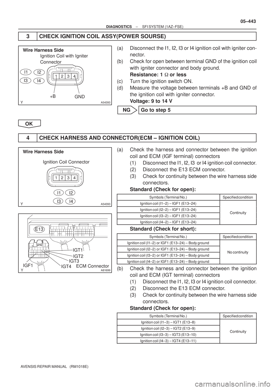
3 CHECK IGNITION COIL ASSY(POWER SOURSE)
(a) Disconnect the I1, I2, I3 or I4 ignition coil with igniter con-
nector.
(b) Check for open between terminal GND of the ignition coil
with igniter connector and body ground.
Resistance: 1 �or less
(c) Turn the ignition switch ON.
(d) Measure the voltage between terminals +B and GND of
the ignition coil with igniter connector.
Voltage: 9 to 14 V
NG Go to step 5
OK
4 CHECK HARNESS AND CONNECTOR(ECM ± IGNITION COIL)
(a) Check the harness and connector between the ignition
coil and ECM (IGF terminal) connectors
(1) Disconnect the I1, I2, I3 or I4 ignition coil connector.
(2) Disconnect the E13 ECM connector.
(3) Check for continuity between the wire harness side
connectors.
Standard (Check for open):
Symbols (Terminal No.)Specified condition
Ignition coil (I1±2) ± IGF1 (E13±24)
Ignition coil (I2±2) ± IGF1 (E13±24)ContinuityIgnition coil (I3±2) ± IGF1 (E13±24)Continuity
Ignition coil (I4±2) ± IGF1 (E13±24)
Standard (Check for short):
Symbols (Terminal No.)Specified condition
Ignition coil (I1±2) or IGF1 (E13±24) ± Body ground
Ignition coil (I2±2) or IGF1 (E13±24) ± Body groundNo continuityIgnition coil (I3±2) or IGF1 (E13±24) ± Body groundNo continuity
Ignition coil (I4±2) or IGF1 (E13±24) ± Body ground
(b) Check the harness and connector between the ignition
coil and ECM (IGT terminal) connectors
(1) Disconnect the I1, I2, I3 or I4 ignition coil connector.
(2) Disconnect the E13 ECM connector.
(3) Check for continuity between the wire harness side
connectors.
Standard (Check for open):
Symbols (Terminal No.)Specified condition
Ignition coil (I1±3) ± IGT1 (E13±8)
Ignition coil (I2±3) ± IGT2 (E13±9)ContinuityIgnition coil (I3±3) ± IGT3 (E13±10)Continuity
Ignition coil (I4±3) ± IGT4 (E13±11)
Page 586 of 5135
B16200
A54393
Wire Harness Side
Ignition Coil with Igniter
Connector
+B
I1I2
I3I4
������A79064IG2 Relay
Engine Room
R/B No. 4 05±444
± DIAGNOSTICSSFI SYSTEM (1AZ±FSE)
AVENSIS REPAIR MANUAL (RM1018E)
Standard (Check for short):
Symbols (Terminal No.)Specified condition
Ignition coil (I1±3) or IGT1 (E13±8) ± Body ground
Ignition coil (I2±3) or IGT2 (E13±9) ± Body groundNo continuityIgnition coil (I3±3) or IGT3 (E13±10) ± Body groundNo continuity
Ignition coil (I4±3) or IGT4 (E13±11) ± Body ground
NG REPAIR OR REPLACE HARNESS OR
CONNECTOR
OK
REPLACE IGNITION COIL ASSY
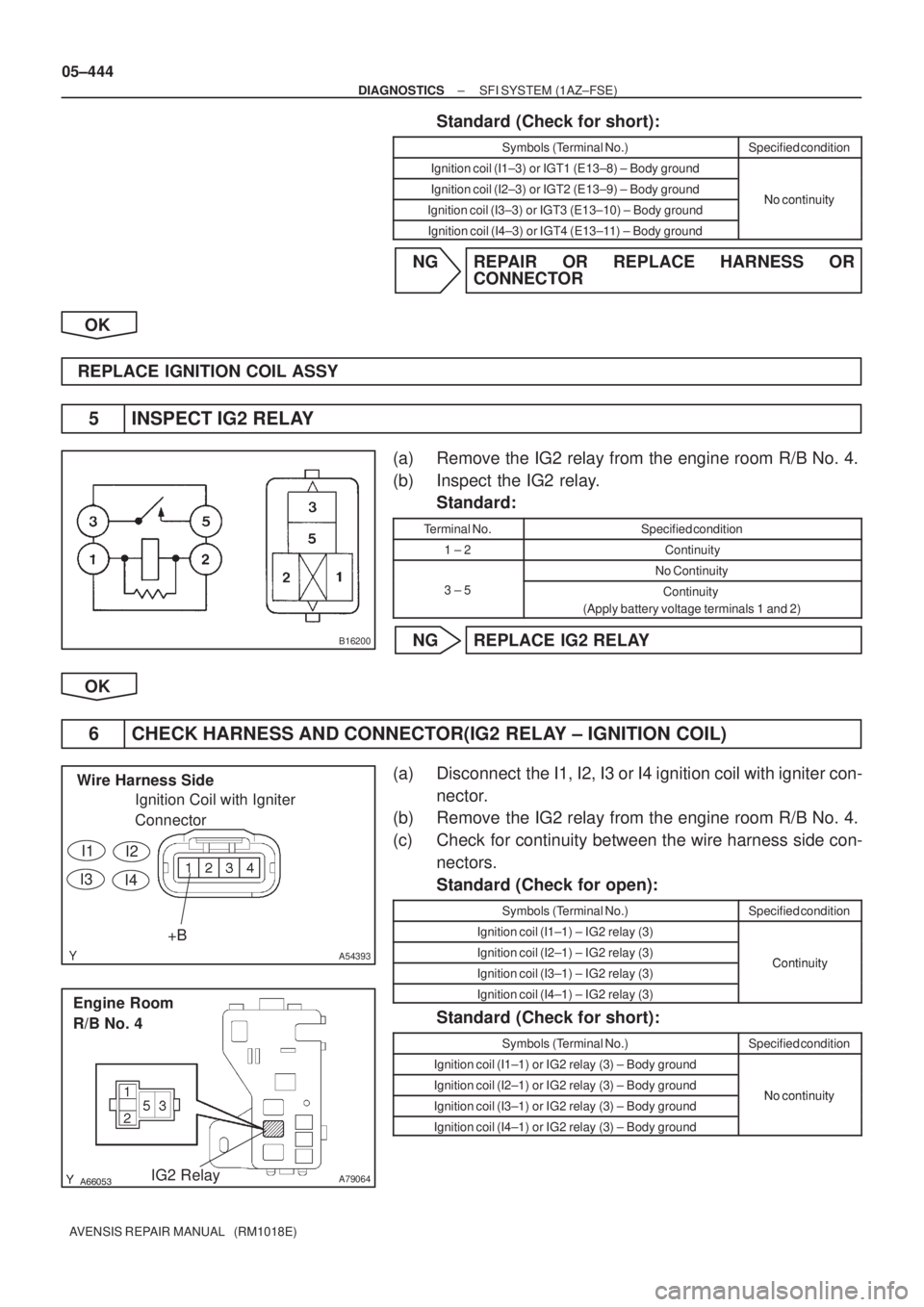
5 INSPECT IG2 RELAY
(a) Remove the IG2 relay from the engine room R/B No. 4.
(b) Inspect the IG2 relay.
Standard:
Terminal No.Specified condition
1 ± 2Continuity
No Continuity
3 ± 5Continuity
(Apply battery voltage terminals 1 and 2)
NG REPLACE IG2 RELAY
OK
6 CHECK HARNESS AND CONNECTOR(IG2 RELAY ± IGNITION COIL)
(a) Disconnect the I1, I2, I3 or I4 ignition coil with igniter con-
nector.
(b) Remove the IG2 relay from the engine room R/B No. 4.
(c) Check for continuity between the wire harness side con-
nectors.
Standard (Check for open):
Symbols (Terminal No.)Specified condition
Ignition coil (I1±1) ± IG2 relay (3)
Ignition coil (I2±1) ± IG2 relay (3)ContinuityIgnition coil (I3±1) ± IG2 relay (3)Continuity
Ignition coil (I4±1) ± IG2 relay (3)
Standard (Check for short):
Symbols (Terminal No.)Specified condition
Ignition coil (I1±1) or IG2 relay (3) ± Body ground
Ignition coil (I2±1) or IG2 relay (3) ± Body groundNo continuityIgnition coil (I3±1) or IG2 relay (3) ± Body groundNo continuity
Ignition coil (I4±1) or IG2 relay (3) ± Body ground
Page 588 of 5135
A76880
FL MAIN
StarterCircuit
Opening Relay
Park/Neutral
Position SWIG2 Relay
AM2
BatteryECM
STA IGSW IGN Ignition SWFuel Pump
ST2IG2
ST
Relay
(NE Signal) (A/T)FC
IG2STTr
(M/T)
(A/T) AM2
± DIAGNOSTICSSFI SYSTEM (1AZ±FSE)
05±507
AVENSIS REPAIR MANUAL (RM1018E)
FUEL PUMP CONTROL CIRCUIT
CIRCUIT DESCRIPTION
In the diagram below, when the engine is cranked, current flows from terminal ST2 of the ignition switch to
the starter relay coil and also current flows to terminal STA of ECM (STA signal).
When the STA signal and NE signal are input to the ECM, Tr is turned ON, current flows to the coil of the
circuit opening relay, the relay switches on, power is supplied to the fuel pump and the fuel pump operates.
While the NE signal is generated (engine running), the ECM keeps Tr ON (circuit opening relay ON) and the
fuel pump also keeps operating.
05CK1±01
Page 592 of 5135
A79096
Driver Side J/B
IGN Fuse
A66267
Ignition Coil Connector
Wire Harness Side
IG2 I13
������A79064IG2 Relay
Engine Room R/B No. 4
������A81706
IG2 Fuse
Engine Room R/B No. 1
2
1
± DIAGNOSTICSSFI SYSTEM (1AZ±FSE)
05±511
AVENSIS REPAIR MANUAL (RM1018E)
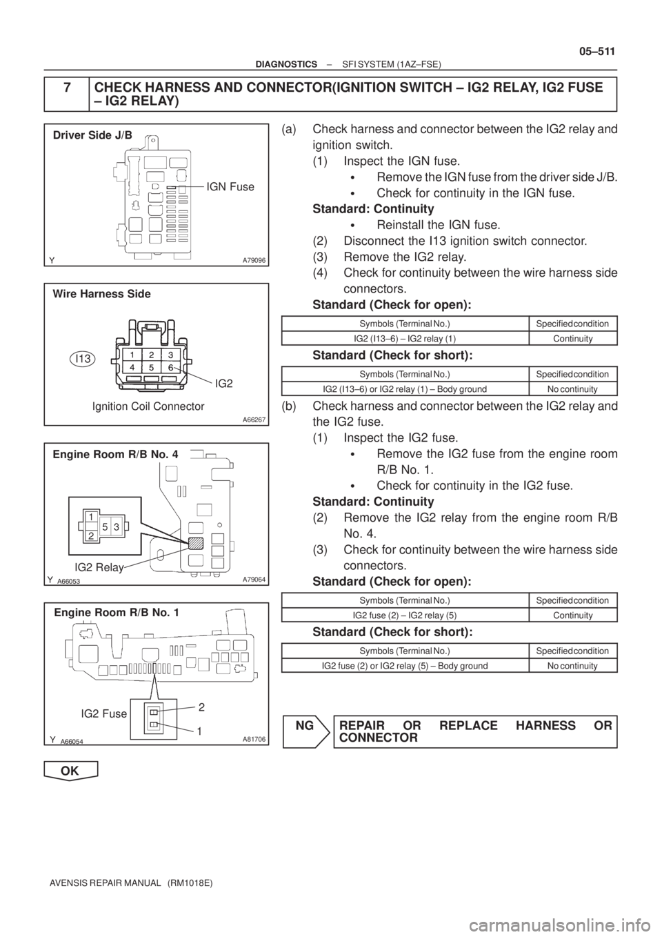
7 CHECK HARNESS AND CONNECTOR(IGNITION SWITCH ± IG2 RELAY, IG2 FUSE
± IG2 RELAY)
(a) Check harness and connector between the IG2 relay and
ignition switch.
(1) Inspect the IGN fuse.
�Remove the IGN fuse from the driver side J/B.
�Check for continuity in the IGN fuse.
Standard: Continuity
�Reinstall the IGN fuse.
(2) Disconnect the I13 ignition switch connector.
(3) Remove the IG2 relay.
(4) Check for continuity between the wire harness side
connectors.
Standard (Check for open):
Symbols (Terminal No.)Specified condition
IG2 (I13±6) ± IG2 relay (1)Continuity
Standard (Check for short):
Symbols (Terminal No.)Specified condition
IG2 (I13±6) or IG2 relay (1) ± Body groundNo continuity
(b) Check harness and connector between the IG2 relay and
the IG2 fuse.
(1) Inspect the IG2 fuse.
�Remove the IG2 fuse from the engine room
R/B No. 1.
�Check for continuity in the IG2 fuse.
Standard: Continuity
(2) Remove the IG2 relay from the engine room R/B
No. 4.
(3) Check for continuity between the wire harness side
connectors.
Standard (Check for open):
Symbols (Terminal No.)Specified condition
IG2 fuse (2) ± IG2 relay (5)Continuity
Standard (Check for short):
Symbols (Terminal No.)Specified condition
IG2 fuse (2) or IG2 relay (5) ± Body groundNo continuity
NG REPAIR OR REPLACE HARNESS OR
CONNECTOR
OK
Page 594 of 5135
A76879
IP1I13
Ignition Switch
IGN Driver Side J/B
E9
E11ECM
Battery FL MAINEFI
No. 1
2
B±G2
118
9
18 4DH
2
E9E9
1 12 31 5
EFI
Relay
D
EFBR GR B±W
DA
J/C 1A
J28IGSW
+B2 MREL
E1
Engine Room
J/B No. 41 4A
4BEngine Room
R/B No. 1 and
Engine Room
J/B No. 1 1EFI AM2
1 211
1 2
B±G6
(RHD) IE4 1 (LHD)
B±R B±R B±R
4 4
4
4
4
4Engine Room
R/B No. 4
Engine
Room
R/B No. 4B±Y
B±W
B±R
ECW±B
B±RB±R B±R
(RHD) (LHD)
D J14 D J28 (RHD)(LHD)
D J14
D J28 D J141
E9 +B (RHD)
(LHD)B±W
B±W (RHD)
(LHD)B±W
J26A
J27E
J8
J/CJ/C
CC
IE12
GR
(LHD) (RHD)IP1 IE42
3
AM2 IG2
05±502
± DIAGNOSTICSSFI SYSTEM (1AZ±FSE)
AVENSIS REPAIR MANUAL (RM1018E)
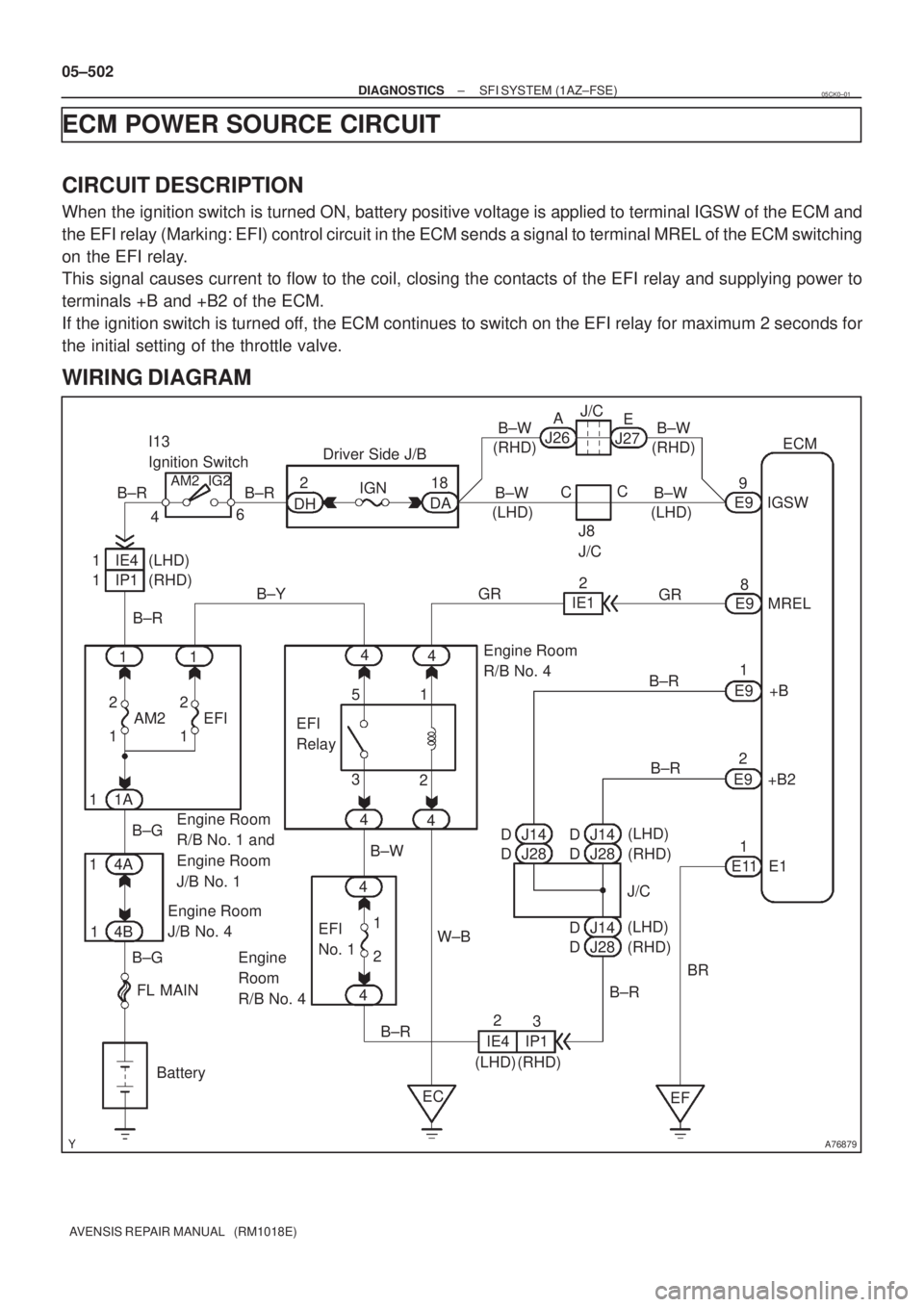
ECM POWER SOURCE CIRCUIT
CIRCUIT DESCRIPTION
When the ignition switch is turned ON, battery positive voltage is applied to terminal IGSW of the ECM and
the EFI relay (Marking: EFI) control circuit in the ECM sends a signal to terminal MREL of the ECM switching
on the EFI relay.
This signal causes current to flow to the coil, closing the contacts of the EFI relay and supplying power to
terminals +B and +B2 of the ECM.
If the ignition switch is turned off, the ECM continues to switch on the EFI relay for maximum 2 seconds for
the initial setting of the throttle valve.
WIRING DIAGRAM
05CK0±01
Page 643 of 5135
A66074
A66289
Inside
05±542
±
DIAGNOSTICS ECD SYSTEM(1CD±FTV)
AVENSIS REPAIR MANUAL (RM1018E)
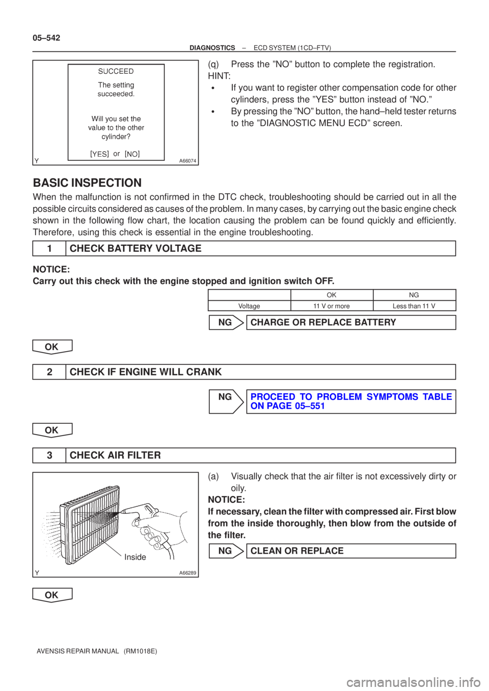
(q)Press the ºNOº button to complete the registration.
HINT:
�If you want to register other compensation code for other
cylinders, press the ºYESº button instead of ºNO.º
�By pressing the ºNOº button, the hand±held tester returns
to the ºDIAGNOSTIC MENU ECDº screen.
BASIC INSPECTION
When the malfunction is not confirmed in the DTC check, troubleshooting shou\
ld be carried out in all the
possible circuits considered as causes of the problem. In many cases, by carrying out the basic engine check
shown in the following flow chart, the location causing the problem can be found quickly and efficiently.
Therefore, using this check is essential in the engine troubleshooting.
1CHECK BATTERY VOLTAGE
NOTICE:
Carry out this check with the engine stopped and ignition switch OFF.
OKNG
Voltage11 V or moreLess than 11 V
NGCHARGE OR REPLACE BATTERY
OK
2CHECK IF ENGINE WILL CRANK
NGPROCEED TO PROBLEM SYMPTOMS TABLE ON PAGE 05±551
OK
3 CHECK AIR FILTER
(a) Visually check that the air filter is not excessively dirty or oily.
NOTICE:
If necessary, clean the filter with compressed air. First blow
from the inside thoroughly, then blow from the outside of
the filter.
NG CLEAN OR REPLACE
OK
Page 644 of 5135
±
DIAGNOSTICS ECD SYSTEM(1CD±FTV)
05±543
AVENSIS REPAIR MANUAL (RM1018E)
4CHECK FUEL QUALITY
(a)Check that only diesel fuel is used
(b)Check that the fuel does not contain any impurity.
NGREPLACE FUEL
OK
5CHECK ENGINE OIL (See page 17±20)
NGADD OR REPLACE
OK
6CHECK ENGINE COOLANT (See page 16±37)
NGREPLACE ENGINE COOLANT (See page 16±44)
OK
7CHECK IDLE SPEED AND MAXIMUM SPEED (See page 14±266)
NGREPAIR OR REPLACE INJECTION PUMP (See page 11±69)
OK
8CHECK DIAGNOSTIC CIRCUIT
NGREPAIR OR REPLACE
OK
9CHECK VACUUM PUMP
NGREPAIR OR REPLACE VACUUM PUMP
OK
PROCEED TO PROBLEM SYMPTOMS TABLE ON PAGE (See page 05±551)
Page 714 of 5135
A33913
A80987
Engine Room R/B No. 3GLOW
Fuse
B08263
OhmmeterContinuity
05±626
±
DIAGNOSTICS ECD SYSTEM(1CD±FTV)
AVENSIS REPAIR MANUAL (RM1018E)
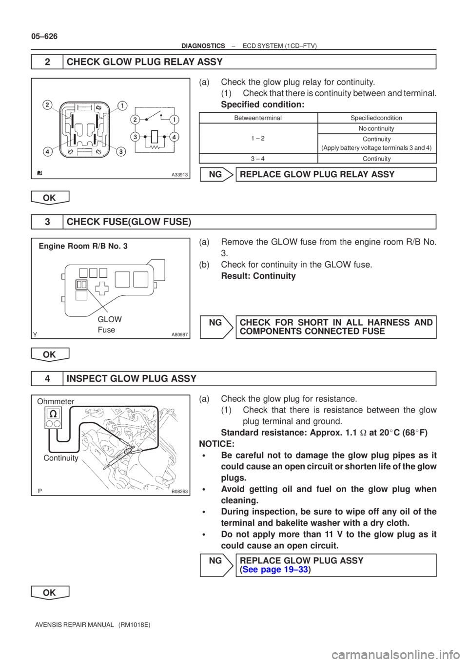
2CHECK GLOW PLUG RELAY ASSY
(a)Check the glow plug relay for continuity. (1)Check that there is continuity between and terminal.
Specified condition:
Between terminalSpecified condition
No continuity
1 ± 2Continuity
(Apply battery voltage terminals 3 and 4)
3 ± 4Continuity
NGREPLACE GLOW PLUG RELAY ASSY
OK
3CHECK FUSE(GLOW FUSE)
(a)Remove the GLOW fuse from the engine room R/B No. 3.
(b)Check for continuity in the GLOW fuse. Result: Continuity
NGCHECK FOR SHORT IN ALL HARNESS AND COMPONENTS CONNECTED FUSE
OK
4INSPECT GLOW PLUG ASSY
(a)Check the glow plug for resistance. (1)Check that there is resistance between the glow
plug terminal and ground.
Standard resistance: Approx. 1.1 � at 20 �C (68 �F)
NOTICE:
�Be careful not to damage the glow plug pipes as it
could cause an open circuit or shorten life of the glow
plugs.
�Avoid getting oil and fuel on the glow plug when
cleaning.
�During inspection, be sure to wipe off any oil of the
terminal and bakelite washer with a dry cloth.
�Do not apply more than 11 V to the glow plug as it
could cause an open circuit.
NGREPLACE GLOW PLUG ASSY (See page 19±33)
OK