Page 2441 of 4555
![NISSAN X-TRAIL 2005 Service Repair Manual DTC P1705 ACCELERATOR PEDAL POSITION (APP) SENSOR
AT-177
[EURO-OBD]
D
E
F
G
H
I
J
K
L
MA
B
AT
2. CHECK INPUT SIGNAL
With CONSULT-II
1. Turn ignition switch ON. (Do not start engine.)
2. Select “](/manual-img/5/57403/w960_57403-2440.png "NISSAN X-TRAIL 2005 Service Repair Manual DTC P1705 ACCELERATOR PEDAL POSITION (APP) SENSOR
AT-177
[EURO-OBD]
D
E
F
G
H
I
J
K
L
MA
B
AT
2. CHECK INPUT SIGNAL
With CONSULT-II
1. Turn ignition switch ON. (Do not start engine.)
2. Select “")
DTC P1705 ACCELERATOR PEDAL POSITION (APP) SENSOR
AT-177
[EURO-OBD]
D
E
F
G
H
I
J
K
L
MA
B
AT
2. CHECK INPUT SIGNAL
With CONSULT-II
1. Turn ignition switch ON. (Do not start engine.)
2. Select “TCM INPUT SIGNALS” in “DATA MONITOR” mode for “A/T” with CONSULT-II.
3. Read out the value of “THRTL POS SEN”.
Without CONSULT-II
1. Turn ignition switch ON. (Do not start engine.)
2. Check voltage between TCM connector terminals.
OK or NG
OK >> GO TO 3.
NG >> Check harness for short or open between ECM and TCM regarding accelerator pedal position
sensor circuit.
3. CHECK DTC
Perform AT- 1 7 3 , "
DTC Confirmation Procedure" .
OK or NG
OK >>INSPECTION END
NG >> GO TO 4.
4. CHECK TCM
1. Check TCM input/output signal. Refer to AT- 9 4 , "
TCM Terminals and Reference Value" .
2. If NG, recheck TCM pin terminals for damage or loose connection with harness connector.
OK or NG
OK >>INSPECTION END
NG >> Repair or replace damaged parts.
Monitor item Condition Display value
THRTL POS SEN (V)When depressing accel-
erator pedal slowly after
warming up engine.
(Voltage rises gradually in
response to throttle posi-
tion.)Fully-closed throttle: 0.8V
Fully-open throttle: 4.4V
LCIA0090E
Name Connec-
tor No. Terminal
No. (Wire
color) ConditionJudge-
mentstan-
dard(Appro
x.)
Accelerator
pedal posi-
tion (APP)
sensor F47 41 (G/Y) -
42 (B)When depressing accel-
erator pedal slowly after
warming up engine.
(Voltage rises gradually
in response to throttle
position.)Fully-
closed
throttle:
0.8V
Fully-open
throttle:
4.4V
SCIA3247E
Page 2442 of 4555
![NISSAN X-TRAIL 2005 Service Repair Manual AT-178
[EURO-OBD]
DTC P1760 OVERRUN CLUTCH SOLENOID VALVE
DTC P1760 OVERRUN CLUTCH SOLENOID VALVEPFP:31940
DescriptionECS004S9
The overrun clutch solenoid valve is activated by the TCM in
response t](/manual-img/5/57403/w960_57403-2441.png "NISSAN X-TRAIL 2005 Service Repair Manual AT-178
[EURO-OBD]
DTC P1760 OVERRUN CLUTCH SOLENOID VALVE
DTC P1760 OVERRUN CLUTCH SOLENOID VALVEPFP:31940
DescriptionECS004S9
The overrun clutch solenoid valve is activated by the TCM in
response t")
AT-178
[EURO-OBD]
DTC P1760 OVERRUN CLUTCH SOLENOID VALVE
DTC P1760 OVERRUN CLUTCH SOLENOID VALVEPFP:31940
DescriptionECS004S9
The overrun clutch solenoid valve is activated by the TCM in
response to signals sent from the park/neutral position (PNP) switch,
overdrive control switch, vehicle speed and throttle position sensors.
The overrun clutch operation will then be controlled.
On Board Diagnosis LogicECS00CUJ
Possible CauseECS00CUK
Check the following items.
�Harness or connector
(The solenoid circuit is open or shorted.)
�Overrun clutch solenoid valve
DTC Confirmation ProcedureECS00CUL
CAUTION:
Always drive vehicle at a safe speed.
NOTE:
If “DTC Confirmation Procedure” has been previously conducted, always turn ignition switch OFF and
wait at least 5 seconds before conducting the next test.
TESTING CONDITION:
Always drive vehicle on a level road to improve accuracy of test.
After the repair, perform the following procedure to confirm the malfunction is eliminated.
WITH CONSULT-II
1. Turn ignition switch ON and select “DATA MONITOR” mode for
“A/T” with CONSULT-II.
2. Start engine.
3. Accelerate vehicle to a speed of more than 10 km/h (6 MPH)
with “D” position (O/D ON).
4. Release accelerator pedal completely with D position (O/D
OFF).
WITH GST
Follow the procedure “WITH CONSULT-II”.
SCIA0718E
Diagnostic trouble code Malfunction is detected when... Check items (Possible cause)
: OVERRUN CLUTCH S/V
TCM detects an improper voltage drop
when it tries to operate the solenoid valve.
�Harness or connectors
(The solenoid circuit is open or shorted.)
�Overrun clutch solenoid valve
: P1760
SAT014K
Page 2515 of 4555
![NISSAN X-TRAIL 2005 Service Repair Manual TROUBLE DIAGNOSIS — INTRODUCTION
AT-251
[EXC.F/EURO-OBD]
D
E
F
G
H
I
J
K
L
MA
B
AT
TROUBLE DIAGNOSIS — INTRODUCTIONPFP:00000
IntroductionECS004TF
The TCM receives a signal from the vehicle speed](/manual-img/5/57403/w960_57403-2514.png "NISSAN X-TRAIL 2005 Service Repair Manual TROUBLE DIAGNOSIS — INTRODUCTION
AT-251
[EXC.F/EURO-OBD]
D
E
F
G
H
I
J
K
L
MA
B
AT
TROUBLE DIAGNOSIS — INTRODUCTIONPFP:00000
IntroductionECS004TF
The TCM receives a signal from the vehicle speed")
TROUBLE DIAGNOSIS — INTRODUCTION
AT-251
[EXC.F/EURO-OBD]
D
E
F
G
H
I
J
K
L
MA
B
AT
TROUBLE DIAGNOSIS — INTRODUCTIONPFP:00000
IntroductionECS004TF
The TCM receives a signal from the vehicle speed sensor, throttle
position sensor or PNP switch and provides shift control or lock-up
control via A/T solenoid valves.
Input and output signals must always be correct and stable in the
operation of the A/T system. The A/T system must be in good oper-
ating condition and be free of valve seizure, solenoid valve malfunc-
tion, etc.
It is much more difficult to diagnose a problem that occurs intermit-
tently rather than continuously. Most intermittent problems are
caused by poor electric connections or improper wiring. In this case,
careful checking of suspected circuits may help prevent the replace-
ment of good parts.
A visual check only, may not find the cause of the problems. A road
test with CONSULT-II or a circuit tester connected should be per-
formed. Follow the “Work Flow”. Refer to AT- 6 1
.
Before undertaking actual checks, take a few minutes to talk with a
customer who approaches with a drive ability complaint. The cus-
tomer can supply good information about such problems, especially
intermittent ones. Find out what symptoms are present and under
what conditions they occur. A “Diagnostic Worksheet” like the exam-
ple (AT- 5 8
) should be used.
Start your diagnosis by looking for “conventional” problems first. This
will help troubleshoot drive ability problems on an electronically con-
trolled engine vehicle.
Also check related Service bulletins for information.
SAT631IA
SAT632I
SEF234G
Page 2524 of 4555
AT-260
[EXC.F/EURO-OBD]
TROUBLE DIAGNOSIS — BASIC INSPECTION
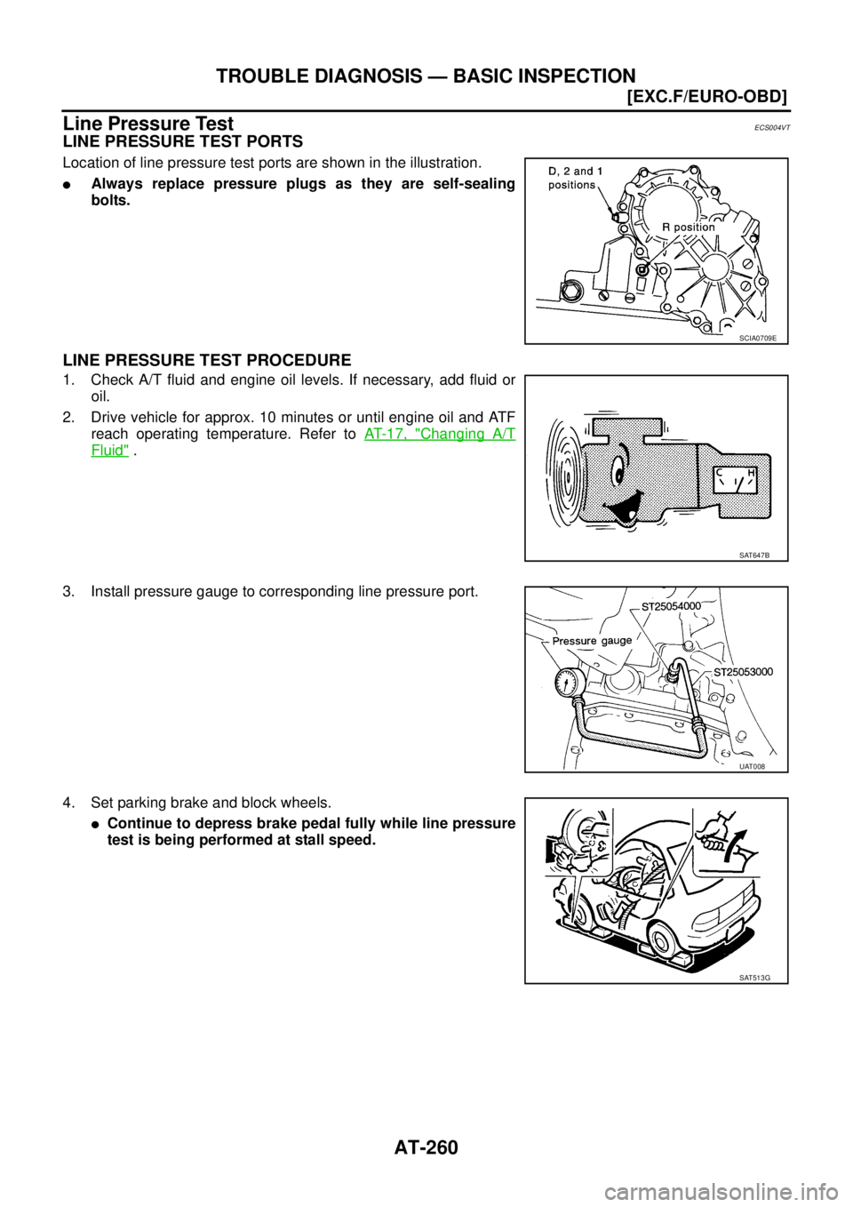
Line Pressure TestECS004VT
LINE PRESSURE TEST PORTS
Location of line pressure test ports are shown in the illustration.
�Always replace pressure plugs as they are self-sealing
bolts.
LINE PRESSURE TEST PROCEDURE
1. Check A/T fluid and engine oil levels. If necessary, add fluid or
oil.
2. Drive vehicle for approx. 10 minutes or until engine oil and ATF
reach operating temperature. Refer to AT- 1 7 , "
Changing A/T
Fluid" .
3. Install pressure gauge to corresponding line pressure port.
4. Set parking brake and block wheels.
�Continue to depress brake pedal fully while line pressure
test is being performed at stall speed.
SCIA0709E
SAT647B
UAT008
SAT513G
Page 2552 of 4555
![NISSAN X-TRAIL 2005 Service Repair Manual AT-288
[EXC.F/EURO-OBD]
TROUBLE DIAGNOSIS — GENERAL DESCRIPTION
*1: These terminals are connected to the ECM.
*2: These terminals are connected to the data link connector.34 W/GPNP switch “D”](/manual-img/5/57403/w960_57403-2551.png "NISSAN X-TRAIL 2005 Service Repair Manual AT-288
[EXC.F/EURO-OBD]
TROUBLE DIAGNOSIS — GENERAL DESCRIPTION
*1: These terminals are connected to the ECM.
*2: These terminals are connected to the data link connector.34 W/GPNP switch “D”")
AT-288
[EXC.F/EURO-OBD]
TROUBLE DIAGNOSIS — GENERAL DESCRIPTION
*1: These terminals are connected to the ECM.
*2: These terminals are connected to the data link connector.34 W/GPNP switch “D”
position
and When setting selector lever to “D”
position.Battery voltage
When setting selector lever to other
positions.0V
35 Y/GPNP switch “R”
positionWhen setting selector lever to “R”
position.Battery voltage
When setting selector lever to other
positions.0V
36 GPNP switch “N” or
“P” positionWhen setting selector lever to “N” or
“P” position.Battery voltage
When setting selector lever to other
positions.0V
39 *1 L/OREngine speed sig-
nal
and Refer to EC-95, "
ECM INSPECTION
TABLE" .—
40 L/BVehicle speed
sensorWhen moving vehicle at 2 to 3 km/h
(1 to 2 MPH) for 1 m (3 ft) or more.Voltage varies
between less
than 0V and
more than 4.5V
41 G/YThrottle position
sensorWhen depressing accelerator pedal
slowly after warming up engine.
(Voltage rises gradually in response
to throttle position.)Fully-closed
throttle: 0.5V
Fully-open throt-
tle: 4V
42 B Sensor ground Always 0V
47 BRA/T fluid tempera-
ture sensorWhen ATF temperature is 20°C
(68°F).1.5V
When ATF temperature is 80°C
(176°F).0.5V
48 B Ground Always 0V Te r m i -
nal No.Wire color Item ConditionJudgementstan-
dard(Approx.)
Page 2612 of 4555
![NISSAN X-TRAIL 2005 Service Repair Manual AT-348
[ALL]
ACCELE RATOR PEDAL POSITION (APP) SENSOR
TERMINALS AND REFERENCE VALUE MEASURED BETWEEN EACH TERMINAL
Diagnostic ProcedureECS00CSG
1. CHECK DTC WITH ECM
�Check P code with CONSULT-II �](/manual-img/5/57403/w960_57403-2611.png "NISSAN X-TRAIL 2005 Service Repair Manual AT-348
[ALL]
ACCELE RATOR PEDAL POSITION (APP) SENSOR
TERMINALS AND REFERENCE VALUE MEASURED BETWEEN EACH TERMINAL
Diagnostic ProcedureECS00CSG
1. CHECK DTC WITH ECM
�Check P code with CONSULT-II �")
AT-348
[ALL]
ACCELE RATOR PEDAL POSITION (APP) SENSOR
TERMINALS AND REFERENCE VALUE MEASURED BETWEEN EACH TERMINAL
Diagnostic ProcedureECS00CSG
1. CHECK DTC WITH ECM
�Check P code with CONSULT-II “ENGINE”.
Turn ignition switch ON and select “SELF DIAGNOSTIC RESULTS” mode for “ENGINE” with CONSULT-II.
Refer to EC-64, "
Malfunction Indicator (MI)" (WITH EURO-OBD) or EC-568, "Malfunction Indicator (MI)"
(WITHOUT EURO-OBD).
OK or NG
OK >> GO TO 2.
NG >> Check accelerator pedal position (APP) sensor circuit for engine control. Refer to EC-409, "
DTC
P2122, P2123 APP SENSOR" , EC-416, "DTC P2127, P2128 APP SENSOR" , EC-432, "DTC
P2138 APP SENSOR" . If CAN communication line is detected, GO TO LAN-4, "CAN COMMUNI-
CATION" .
Termi-
nal No.Wire color Item ConditionJudgement stan-
dard
(Approx.)
32 RThrottle position
sensor
(Power source)
or When turning ignition switch “ON”. 4.5 - 5.5V
When turning ignition switch “OFF”. 0V
41 G/YThrottle position
sensorWhen depressing accelerator pedal
slowly after warming up engine.
(Voltage rises gradually in response
to throttle position.)Fully-closed throttle:
0.5V
Fully-open throttle:
4V
42 B Sensor ground Always 0V
Page 2613 of 4555
![NISSAN X-TRAIL 2005 Service Repair Manual ACCELE RATOR PEDAL POSITION (APP) SENSOR
AT-349
[ALL]
D
E
F
G
H
I
J
K
L
MA
B
AT
2. CHECK INPUT SIGNAL
With CONSULT-II
1. Turn ignition switch ON. (Do not start engine.)
2. Select “TCM INPUT SIGN](/manual-img/5/57403/w960_57403-2612.png "NISSAN X-TRAIL 2005 Service Repair Manual ACCELE RATOR PEDAL POSITION (APP) SENSOR
AT-349
[ALL]
D
E
F
G
H
I
J
K
L
MA
B
AT
2. CHECK INPUT SIGNAL
With CONSULT-II
1. Turn ignition switch ON. (Do not start engine.)
2. Select “TCM INPUT SIGN")
ACCELE RATOR PEDAL POSITION (APP) SENSOR
AT-349
[ALL]
D
E
F
G
H
I
J
K
L
MA
B
AT
2. CHECK INPUT SIGNAL
With CONSULT-II
1. Turn ignition switch ON. (Do not start engine.)
2. Select “TCM INPUT SIGNALS” in “DATA MONITOR” mode for “A/T” with CONSULT-II.
3. Read out the value of “THRTL POS SEN”.
Without CONSULT-II
1. Turn ignition switch ON. (Do not start engine.)
2. Check voltage between TCM connector terminals.
OK or NG
OK >> GO TO 3.
NG >> Check harness for short or open between ECM and TCM regarding throttle position sensor circuit.
3. CHECK DTC
Perform AT- 3 4 5 , "
DTC Confirmation Procedure" .
OK or NG
OK >>INSPECTION END
NG >> GO TO 5.
4. CHECK TCM
1. Check TCM input/output signal. Refer to AT- 9 4 , "
TCM Terminals and Reference Value" .
2. If NG, recheck TCM pin terminals for damage or loose connection with harness connector.
OK or NG
OK >>INSPECTION END
NG >> Repair or replace damaged parts.
Monitor item Condition Display value
THRTL POS SEN (V)When depressing accel-
erator pedal slowly after
warming up engine.
(Voltage rises gradually in
response to throttle posi-
tion.)Fully-closed throttle: 0.5V
Fully-open throttle: 4V
LCIA0090E
Name Connec-
tor No. Terminal
No. (Wire
color) ConditionJudge-
mentstan-
dard(Appro
x.)
Accelerator
pedal posi-
tion (APP)
sensor F47 41(G/Y) -
42(B)When depressing accel-
erator pedal slowly after
warming up engine.
(Voltage rises gradually
in response to throttle
position.)Fully-
closed
throttle:
0.5V
Fully-open
throttle: 4V
SCIA3247E
Page 2614 of 4555
![NISSAN X-TRAIL 2005 Service Repair Manual AT-350
[ALL]
SHIFT SOLENOID VALVE A
SHIFT SOLENOID VALVE APFP:31940
DescriptionECS004TS
Shift solenoid valves A and B are turned ON or OFF by the TCM in
response to signals sent from the PNP switch,](/manual-img/5/57403/w960_57403-2613.png "NISSAN X-TRAIL 2005 Service Repair Manual AT-350
[ALL]
SHIFT SOLENOID VALVE A
SHIFT SOLENOID VALVE APFP:31940
DescriptionECS004TS
Shift solenoid valves A and B are turned ON or OFF by the TCM in
response to signals sent from the PNP switch,")
AT-350
[ALL]
SHIFT SOLENOID VALVE A
SHIFT SOLENOID VALVE APFP:31940
DescriptionECS004TS
Shift solenoid valves A and B are turned ON or OFF by the TCM in
response to signals sent from the PNP switch, vehicle speed and
throttle position sensors. Gears will then be shifted to the optimum
position.
CONSULT-II Reference ValueECS00CSI
Remarks: Specification data are reference values.
On Board Diagnosis LogicECS00CSJ
Possible CauseECS00CSK
Check the following items.
�Harness or connector
(The solenoid circuit is open or shorted.)
�Shift solenoid valve A
DTC Confirmation ProcedureECS00CSL
CAUTION:
�Always drive vehicle at a safe speed.
�If performing this “DTC Confirmation Procedure” again, always turn ignition switch OFF and wait
at least 10 seconds before continuing.
After the repair, perform the following procedure to confirm the malfunction is eliminated.
SCIA0718E
Gear position 1 2 3 4
Shift solenoid valve A ON (Closed) OFF (Open) OFF (Open) ON (Closed)
Shift solenoid valve B ON (Closed) ON (Closed) OFF (Open) OFF (Open)
Monitor item Condition Display value
SHIFT S/V A (ON/OFF)When shift solenoid valve A operates.
(When driving in “D
1 ” or “D4 ”.)ON
When shift solenoid valve A does not operate.
(When driving in “D
2 ” or “D3 ”.)OFF
Diagnostic trouble code Malfunction is detected when... Check items (Possible cause)
: SHIFT SOLENOID/VA
TCM detects an improper voltage drop
when it tries to operate the solenoid valve.
�Harness or connectors
(The solenoid circuit is open or shorted.)
�Shift solenoid valve A
: 4th judgement flicker