Page 4412 of 4555
![NISSAN X-TRAIL 2005 Service Repair Manual LAN-168
[CAN]
CAN SYSTEM (TYPE 9)
2. CHECK HARNESS FOR OPEN CIRCUIT
1. Disconnect ECM connector.
2. Check resistance between ECM harness connector M118 termi-
nals 95 (G/R) and 87 (GY/R).
OK or NG
O](/manual-img/5/57403/w960_57403-4411.png "NISSAN X-TRAIL 2005 Service Repair Manual LAN-168
[CAN]
CAN SYSTEM (TYPE 9)
2. CHECK HARNESS FOR OPEN CIRCUIT
1. Disconnect ECM connector.
2. Check resistance between ECM harness connector M118 termi-
nals 95 (G/R) and 87 (GY/R).
OK or NG
O")
LAN-168
[CAN]
CAN SYSTEM (TYPE 9)
2. CHECK HARNESS FOR OPEN CIRCUIT
1. Disconnect ECM connector.
2. Check resistance between ECM harness connector M118 termi-
nals 95 (G/R) and 87 (GY/R).
OK or NG
OK >> Replace ECM.
NG >> Repair harness between ECM and ESP/TCS/ABS con-
trol unit.
ESP/TCS/ABS Control Unit Circuit InspectionEKS00NLE
1. CHECK CONNECTOR
1. Turn ignition switch OFF.
2. Disconnect the battery cable from the negative terminal.
3. Check terminals and connector of ESP/TCS/ABS control unit for damage, bend and loose connection
(control unit side and harness side).
OK or NG
OK >> GO TO 2.
NG >> Repair terminal or connector.
2. CHECK HARNESS FOR OPEN CIRCUIT
1. Disconnect ESP/TCS/ABS control unit connector.
2. Check resistance between ESP/TCS/ABS control unit harness
connector E122 terminals 61 (W) and 63 (R).
OK or NG
OK >> Replace ESP/TCS/ABS control unit.
NG >> Repair harness between ESP/TCS/ABS control unit and
harness connector E116.
Steering Angle Sensor Circuit InspectionEKS00NLF
1. CHECK CONNECTOR
1. Turn ignition switch OFF.
2. Disconnect the battery cable from the negative terminal.
3. Check terminals and connector of steering angle sensor for damage, bend and loose connection (sensor
side and harness side).
OK or NG
OK >> GO TO 2.
NG >> Repair terminal or connector.95 (G/R) - 87 (GY/R) : Approx. 108 - 132 Ω
SKIB0120E
61 (W) - 63 (R) : Approx. 54 - 66 Ω
PKIA9632E
Page 4413 of 4555
![NISSAN X-TRAIL 2005 Service Repair Manual CAN SYSTEM (TYPE 9)
LAN-169
[CAN]
C
D
E
F
G
H
I
J
L
MA
B
LAN
2. CHECK HARNESS FOR OPEN CIRCUIT
1. Disconnect steering angle sensor connector.
2. Check resistance between steering angle sensor harnes](/manual-img/5/57403/w960_57403-4412.png "NISSAN X-TRAIL 2005 Service Repair Manual CAN SYSTEM (TYPE 9)
LAN-169
[CAN]
C
D
E
F
G
H
I
J
L
MA
B
LAN
2. CHECK HARNESS FOR OPEN CIRCUIT
1. Disconnect steering angle sensor connector.
2. Check resistance between steering angle sensor harnes")
CAN SYSTEM (TYPE 9)
LAN-169
[CAN]
C
D
E
F
G
H
I
J
L
MA
B
LAN
2. CHECK HARNESS FOR OPEN CIRCUIT
1. Disconnect steering angle sensor connector.
2. Check resistance between steering angle sensor harness con-
nector M81 terminals 4 (W) and 5 (R).
OK or NG
OK >> Replace steering angle sensor.
NG >> Repair harness between steering angle sensor and har-
ness connector M75.
Combination Meter Circuit InspectionEKS00NLH
1. CHECK CONNECTOR
1. Turn ignition switch OFF.
2. Disconnect the battery cable from the negative terminal.
3. Check terminals and connector of combination meter for damage, bend and loose connection (meter side
and harness side).
OK or NG
OK >> GO TO 2.
NG >> Repair terminal or connector.
2. CHECK HARNESS FOR OPEN CIRCUIT
1. Disconnect combination meter connector.
2. Check resistance between combination meter harness connec-
tor M44 terminals 22 (W) and 23 (R).
OK or NG
OK >> Replace combination meter.
NG >> Repair harness between combination meter and steer-
ing angle sensor.
CAN Communication Circuit InspectionEKS00NLI
1. CHECK CONNECTOR
1. Turn ignition switch OFF.
2. Disconnect the battery cable from the negative terminal.
3. Check following terminals and connectors for damage, bend and loose connection (control module side,
control unit side, sensor side, meter side, connector side and harness side).
–ECM
–ESP/TCS/ABS control unit
–Steering angle sensor
–Combination meter
–Between ECM and combination meter
OK or NG
OK >> GO TO 2.
NG >> Repair terminal or connector.4 (W) - 5 (R) : Approx. 54 - 66 Ω
SKIA6870E
22 (W) - 23 (R) : Approx. 108 - 132 Ω
SKIA9780E
Page 4414 of 4555
![NISSAN X-TRAIL 2005 Service Repair Manual LAN-170
[CAN]
CAN SYSTEM (TYPE 9)
2. CHECK HARNESS FOR SHORT CIRCUIT
1. Disconnect ECM connector and harness connector M75.
2. Check continuity between ECM harness connector M118 termi-
nals 95 (G/R](/manual-img/5/57403/w960_57403-4413.png "NISSAN X-TRAIL 2005 Service Repair Manual LAN-170
[CAN]
CAN SYSTEM (TYPE 9)
2. CHECK HARNESS FOR SHORT CIRCUIT
1. Disconnect ECM connector and harness connector M75.
2. Check continuity between ECM harness connector M118 termi-
nals 95 (G/R")
LAN-170
[CAN]
CAN SYSTEM (TYPE 9)
2. CHECK HARNESS FOR SHORT CIRCUIT
1. Disconnect ECM connector and harness connector M75.
2. Check continuity between ECM harness connector M118 termi-
nals 95 (G/R) and 87 (GY/R).
OK or NG
OK >> GO TO 3.
NG >> Repair harness between ECM and harness connector
M75.
3. CHECK HARNESS FOR SHORT CIRCUIT
Check continuity between ECM harness connector M118 terminals
95 (G/R), 87 (GY/R) and ground.
OK or NG
OK >> GO TO 4.
NG >> Repair harness between ECM and harness connector
M75.
4. CHECK HARNESS FOR SHORT CIRCUIT
1. Disconnect ESP/TCS/ABS control unit connector.
2. Check continuity between ESP/TCS/ABS control unit harness
connector E122 terminals 61 (W) and 63 (R).
OK or NG
OK >> GO TO 5.
NG >> Repair harness between ESP/TCS/ABS control unit and
harness connector E116.
5. CHECK HARNESS FOR SHORT CIRCUIT
Check continuity between ESP/TCS/ABS control unit harness con-
nector E122 terminals 61 (W), 63 (R) and ground.
OK or NG
OK >> GO TO 6.
NG >> Repair harness between ESP/TCS/ABS control unit and
harness connector E116. 95 (G/R) - 87 (GY/R) : Continuity should not exist.
SKIB0120E
95 (G/R) - Ground : Continuity should not exist.
87 (GY/R) - Ground : Continuity should not exist.
SKIB0121E
61 (W) - 63 (R) : Continuity should not exist.
PKIA9632E
61 (W) - Ground : Continuity should not exist.
63 (R) - Ground : Continuity should not exist.
PKIA9633E
Page 4428 of 4555

PG-12
POWER SUPPLY ROUTING
Fuse EKS00324
�If fuse is blown, be sure to eliminate cause of malfunction before
installing new fuse.
�Use fuse of specified rating. Never use fuse of more than speci-
fied rating.
�Do not partially install fuse; always insert it into fuse holder prop-
erly.
�Remove fuse for “ELECTRICAL PARTS (BAT)” if vehicle is not
used for a long period of time.
Fusible Link EKS00325
A melted fusible link can be detected either by visual inspection or by
feeling with finger tip. If its condition is questionable, use circuit
tester or test lamp.
CAUTION:
�If fusible link should melt, it is possible that critical circuit
(power supply or large current carrying circuit) is shorted.
In such a case, carefully check and eliminate cause of mal-
function.
�Never wrap outside of fusible link with vinyl tape. Important:
Never let fusible link touch any other wiring harness, vinyl
or rubber parts.
Circuit Breaker EKS00326
The PTC thermistor generates heat in response to current flow. The
temperature (and resistance) of the thermistor element varies with
current flow. Excessive current flow will cause the element's temper-
ature to rise. When the temperature reaches a specified level, the
electrical resistance will rise sharply to control the circuit current.
Reduced current flow will cause the element to cool. Resistance falls
accordingly and normal circuit current flow is allowed to resume.
CEL083
CKWA0098E
SEL109W
Page 4482 of 4555

PG-66
HARNESS
ESP BRC ESP/TCS/ABS Control System
ETC1 EC Electric Throttle Control Function
ETC2 EC Electric Throttle Control Motor Relay
ETC3 EC Electric Throttle Control Motor
F/FOG LT Front Fog Lamp
F/PUMP EC Fuel Pump
FIAR EC Fuel Injector Adjustment Resistor
FRO2 EC Front Heated Oxygen Sensor
FRO2/H EC Front Heated Oxygen Sensor Heater
FRPS EC Fuel Rail Pressure Sensor
FTP EC Fuel Transport Pump
FTS AT A/T Fluid Temperature Sensor Circuit
FTS EC Fuel Temperature Sensor
FUEL EC Fuel Injection System Function
GLORLY EC Glow Relay
GLOW EC Glow Control System
H/AIM LT Headlamp Aiming Control System
H/LAMP LT Headlamp
HEATER MTC Heater System
HLC WW Headlamp Cleaner
HO2S1 EC Heated Oxygen Sensor 1
HO2S1H EC Heated Oxygen Sensor 1 Heater
HO2S2 EC Heated Oxygen Sensor 2
HO2S2H EC Heated Oxygen Sensor 2 Heater
HORN WW Horn
HSEAT SE Heated Seat
IATS EC Intake Air Temperature Sensor
IATSEN EC Intake Air Temperature Sensor
IGNSYS EC Ignition System
ILL LT Illumination
INJ/PW EC Fuel Injector Power Supply Circuit
INJECT EC Fuel Injector
INT/L LT Map Lamp
IVC EC Intake Valve Timing Control Solenoid Valve
KS EC Knock Sensor
LOAD EC Electrical Load Signal
LPSV AT Line Pressure Solenoid Valve
MAFS EC Mass Air Flow Sensor
MAIN AT Main Power Supply and Ground Circuit
MAIN EC Main Power Supply and Ground Circuit
METER DI Speedometer, Tachometer, Temp. and Fuel Gauges
MIL/DL EC MIL & Data Link Connector
MIRROR GW Door Mirror
MULTI BL Multi-Remote Control SystemCode Section Wiring Diagram Name
Page 4491 of 4555
HARNESS CONNECTOR
PG-75
C
D
E
F
G
H
I
J
L
MA
B
PG
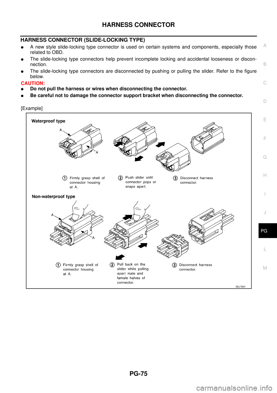
HARNESS CONNECTOR (SLIDE-LOCKING TYPE)
�A new style slide-locking type connector is used on certain systems and components, especially those
related to OBD.
�The slide-locking type connectors help prevent incomplete locking and accidental looseness or discon-
nection.
�The slide-locking type connectors are disconnected by pushing or pulling the slider. Refer to the figure
below.
CAUTION:
�Do not pull the harness or wires when disconnecting the connector.
�Be careful not to damage the connector support bracket when disconnecting the connector.
[Example]
SEL769V