Page 7 of 4555

PRECAUTIONS
GI-5
C
D
E
F
G
H
I
J
K
L
MB
GI
�Use approved bonding agent, sealants or their equivalents when required.
�Use tools and recommended special tools where specified for safe and efficient service repairs.
�When repairing the fuel, oil, water, vacuum or exhaust systems, check all affected lines for leaks.
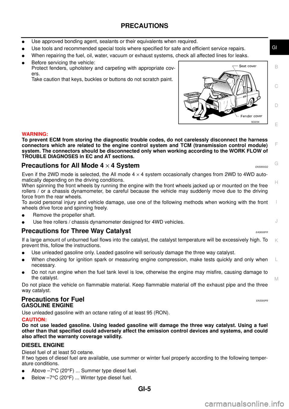
�Before servicing the vehicle:
Protect fenders, upholstery and carpeting with appropriate cov-
ers.
Take caution that keys, buckles or buttons do not scratch paint.
WARNING:
To prevent ECM from storing the diagnostic trouble codes, do not carelessly disconnect the harness
connectors which are related to the engine control system and TCM (transmission control module)
system. The connectors should be disconnected only when working according to the WORK FLOW of
TROUBLE DIAGNOSES in EC and AT sections.
Precautions for All Mode 4 × 4 SystemEAS000GQ
Even if the 2WD mode is selected, the All mode 4 × 4 system occasionally changes from 2WD to 4WD auto-
matically depending on the driving conditions.
When spinning the front wheels by running the engine with the front wheels jacked up or mounted on the free
rollers / or a chassis dynamometer, be careful because the vehicle may suddenly move due to the driving
force from the rear wheels.
To avoid personal injury and vehicle damage, use one of the following methods when working with the front
wheels drive force and spinning freely.
� Remove the propeller shaft.
� Use free rollers / chassis dynamometer designed for 4WD vehicles.
Precautions for Three Way CatalystEAS000FR
If a large amount of unburned fuel flows into the catalyst, the catalyst temperature will be excessively high. To
prevent this, follow the instructions.
�Use unleaded gasoline only. Leaded gasoline will seriously damage the three way catalyst.
�When checking for ignition spark or measuring engine compression, make tests quickly and only when
necessary.
�Do not run engine when the fuel tank level is low, otherwise the engine may misfire, causing damage to
the catalyst.
Do not place the vehicle on flammable material. Keep flammable material off the exhaust pipe and the three
way catalyst.
Precautions for FuelEAS000P9
GASOLINE ENGINE
Use unleaded gasoline with an octane rating of at least 95 (RON).
CAUTION:
Do not use leaded gasoline. Using leaded gasoline will damage the three way catalyst. Using a fuel
other than that specified could adversely affect the emission control devices and systems, and could
also affect the warranty coverage validity.
DIESEL ENGINE
Diesel fuel of at least 50 cetane.
If two types of diesel fuel are available, use summer or winter fuel properly according to the following temper-
ature conditions.
�Above –7°C (20°F) ... Summer type diesel fuel.
�Below –7°C (20°F) ... Winter type diesel fuel.
SGI234
Page 71 of 4555
AIR CLEANER AND AIR DUCT
EM-17
[QR]
C
D
E
F
G
H
I
J
K
L
MA
EM
6. Remove resonator in fender lifting left fender protector, as necessary.
INSTALLATION
Note the following, and install in the reverse order of removal.
�Align marks. Attach each joint. Screw clamps firmly.
Changing Air Cleaner FilterEBS0123Q
REMOVAL
1. Unfasten clips and lift up air cleaner case upper.
2. Remove air cleaner filter.
INSTALLATION
Installation is the reverse order of removal.
Page 2672 of 4555
AT-408
[ALL]
ON-VEHICLE SERVICE
Park/Neutral Position (PNP) SwitchECS00CRB
COMPONENTS
REMOVAL AND INSTALLATION
Removal
1. Set select lever in N position.
2. Remove front tire LH from vehicle.
3. Remove LH splash guard. (Front fender side) Refer to EI-21, "
Removal and Installation" .
4. Remove engine under cover.
5. Remove control cable end from manual shaft.
6. Remove PNP switch fixing bolts.
7. Remove PNP switch from transaxle assembly.
Installation
Note the following, and install in the reverse order of removal.
�Align PNP switch position when installing.
1. Transaxle assembly 2. PNP switch
SCIA4855E
SCIA3156E
SCIA3154E
Page 2676 of 4555
AT-412
[ALL]
ON-VEHICLE SERVICE
Revolution Sensor ReplacementECS0040G
COMPONENTS
1. Remove front tire LH from vehicle.
2. Remove LH splash guard.(Front fender side) Refer toEI-21, "
Removal and Installation" .
3. Disconnect revolution sensor harness connector.
4. Remove harness bracket from transaxle assembly.
5. Remove revolution sensor from transaxle assembly.
Installation
Note the following, and install in the reverse order of removal.
CAUTION:
�Do not reuse O-ring.
�Apply petroleum jelly to O-ring.
1. transaxle assembly 2. Revolution sensor 3. O-ring
SCIA4864E
SCIA2788E
Page 3594 of 4555
BL-12
HOOD
HOODPFP:65100
Fitting AdjustmentEIS009QH
LONGITUDINAL AND LATERAL CLEARANCE ADJUSTMENT
1. Remove hood lock assembly, loosen the hood hinge nuts and close the hood.
2. Adjust the lateral and longitudinal clearance, and open the hood to tighten the hood hinge mounting bolts
to the specified torque.
3. Install the hood lock temporarily, and align the hood striker and lock so that the centers of striker and lock
become vertical viewed from the front, by moving the hood lock laterally.
4. Tighten hood lock mounting bolts to the specified torque.
FRONT END HEIGHT ADJUSTMENT
1. Remove the hood lock and adjust the height by rotating the bumper rubber until the hood becomes 1 to1.5
mm (0.04 to 0.059 in) lower than the fender.
PIIB1215E
Page 3595 of 4555
HOOD
BL-13
C
D
E
F
G
H
J
K
L
MA
B
BL
2. Temporarily tighten the hood lock, and position it by engaging it with the hood striker. Check the lock and
striker for looseness, and tighten the hood lock mounting bolts to the specified torque.
CAUTION:
Adjust right/left clearance between hood and each part to the following specification.
Hood and front grille (A–A) : Less than 1.0 mm (0.04 in)
Hood and fender (B–B) : Less than 1.0 mm (0.04 in)
Page 3596 of 4555

BL-14
HOOD
SURFACE HEIGHT ADJUSTMENT
1. Remove hood lock, and adjust the surface height difference of hood, fender and headlamp according to
the fitting standard dimension, by rotating RH and LH bumper rubbers.
2. Install hood lock temporarily, and move hood lock laterally until the centers of striker and lock become ver-
tical when viewed from the front.
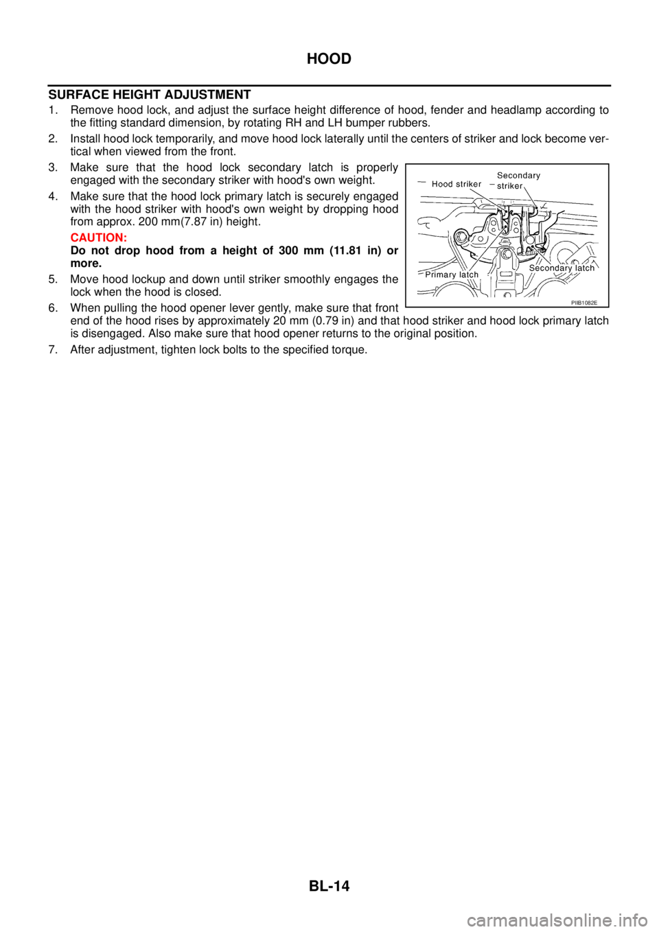
3. Make sure that the hood lock secondary latch is properly
engaged with the secondary striker with hood's own weight.
4. Make sure that the hood lock primary latch is securely engaged
with the hood striker with hood's own weight by dropping hood
from approx. 200 mm(7.87 in) height.
CAUTION:
Do not drop hood from a height of 300 mm (11.81 in) or
more.
5. Move hood lockup and down until striker smoothly engages the
lock when the hood is closed.
6. When pulling the hood opener lever gently, make sure that front
end of the hood rises by approximately 20 mm (0.79 in) and that hood striker and hood lock primary latch
is disengaged. Also make sure that hood opener returns to the original position.
7. After adjustment, tighten lock bolts to the specified torque.
PIIB1082E
Page 3600 of 4555
BL-18
DOOR
DOORPFP:80100
Fitting AdjustmentEIS00A67
FRONT DOOR
Longitudinal clearance and surface height adjustment at front end
1. Remove fender protector. Refer to EI-21, "FENDER PROTECTOR" .
2. Working from the inside the fender, loosen hinge mount bolts on the body. Lift rear end of the front door to
adjust clearance and surface difference properly.
REAR DOOR
Longitudinal clearance and surface height adjustment at front end
1. Remove upper and lower garnishes on the center pillar. Refer to EI-35, "BODY SIDE TRIM" .
2. Loosen mounting bolts from outside of vehicle, mounting nuts from inside of vehicle. Open rear door.
Raise rear end of it to adjust.
STRIKER ADJUSTMENT
Adjust striker until it is parallel to the lock engagement direction.
PIIA3652E
PIIA0555E